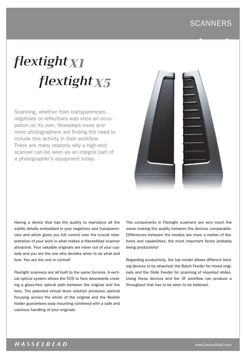
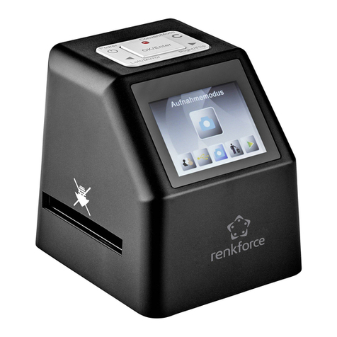
Hasselblad Flextight X5 User manual

User Manual
Flextight X5 / X1
English – v/1.5

Table of contents
Warnings and Restrictions 4
System Requirements 4
Parts and components 5
Front panel 5
Back panel and cutaway view 6
Setting up the Scanner 7
Environmental Requirements
Electrical Requirements
Installation Procedure, FireWire Interface
Operating Instructions 9
Resolutions 10
True Resolutions
Calibrating the Scanner 11
Focus Calibration 12
White Calibration for Reflectives 13
The Light Tubes 14
Cleaning the External Surface of the Scanner 16
Disposal 16
Technical Specifications 16
FCC Notice 17
CE - Declaration of conformity 18
Flextight X1 18
Flextight X5 19

Removal and both utilize Hasselblad’s unique FlexColor
software and 3F – Flexible File Format. These features pro-
duce a digital data management system to provide users
with a fully integrated workow solution that spans from
image capture to output. Both scanners are PC and Mac
compatible using a FireWire interface.
The Flextight scanners also include a full selection of hold-
ers for mounting all of the most common original formats
without requiring gel, tape or glass plates and include a
full selection of the most common negative lm set-up
proles. Support for special formats, such as panoramas,
can also be customised and supplied by Hasselblad. The
scanners use glass-free original holders that ‘ex’ the
original during the scanning process to form a completely
straight line that places nothing between the original and
the electronic image sensor. This ensures that the quality
remains at its highest level without glass distortions and
other unwanted artifacts.
For the optimum in investment security, a Flextight X1
can be modied and upgraded to a Flextight X5 model at
a later date for approximately the dierence in price be-
tween the two scanners. Either way you can rest
assured you have made the right choice.
The supreme Hasselblad potential is there,
it’s up to you to exploit it!
The Flextight X1 and the Flextight X5 satisfy the demand
for image quality and speed requirements from profes-
sional photographers and production environments alike.
Developed around Hasselblad’s patented virtual drum
design and exible magnetic holder and incorporating a
3x8000 optic CCD sensor and a Linos (Rodenstock) lens,
both scanners are fast, easy-to-use and oer unparalleled
image quality. They also feature a new time-saving facility
– an ‘Auto Scan’ button, which with one press automati-
cally delivers a superb, high resolution scan.
The Flextight X1 scans 35mm originals at a maximum
non-interpolated optical resolution of 6300 dpi at a maxi-
mum speed of 60MB per minute while the Flextight X5
scans 35mm originals at up to 8000 dpi and at 300MB per
minute, making it the world’s fastest, high-end scanner.
The Flextight X5 also has an A4 reective scanning op-
tion, can take a batch or a slide feeder and incorporates
Hasselblad’s active cooling capability, where an electronic
device is placed directly on the CCD to cool it down and
prevent an increase in electrical noise.
As with all Hasselblad scanners, the Flextight X1 and
Flextight X5 oer outstanding sharpness and image qual-
ity and are designed to bring out the nest details and
the full tonal range from the professional photographer’s
negatives or transparencies. Both Flextight models oer a
maximum non-interpolated, optical resolution of 3200 dpi
in true 8 or 16 bit colour from 60mm originals and 2040
dpi from 4” x 5” originals, both positive and negative. The
two scanners also provide automatic frame detection,
batch scanning, automatic focus and calibration, hard-
ware (Flextight X5 only) and software-based Auto Dust
3

Warnings and restrictions
•Readalloftheincludeddocumentationbeforeattemptingtoinstallandusethe
scanner.
•Donottouchtheoriginalsand/ortheoriginalholderwhilescanning.
•Donotstartscanningorpreviewinguntilanoriginalholderwithanoriginalhas
beenmounted.
•eoriginalholderisonlytobemountedorremovedwhenthedrumisintheload
position.
•Whenyouturnonthescanner,thedrumwillrolltotheloadposition,ifitisnot
therealready.Donottouchthescannerwhilethedrumisrotating.
•Donotplaceyourngersoranyotherobjectintothescannerwhileitisconnected
topower.
•Beforeservicingoropeningthescanner,thepowersupplymustbedisconnected
fromthemains(unplugged).Itisnotsucientsimplytopresstheon/obutton.
•Installthescannerinalocationwherechildrencannotgettoit.Itcontainssmall
openingsandmovingpartsthatcancauseinjury.
System requirements
BelowarethebasichardwarerequirementsforthePCorMacintoshsystemtowhich
thescanneristobeconnected.Forinformationabouttheprocessor,operating
system,RAMandharddiskrequirementspleaserefertothe“SowareReference”
manual,thatcomeswiththeFlexColorsoware.
•Screenresolutionofminimum800x600pixelswithtruecolors(24-bits).
•Mouseorotherpointingdevice.
•FireWireinterface.
Preventive maintenance
AllFlextightscannersshouldbeservicedevery25,000scansorevery12months,
whichevercomesrst.IfaFeederismounted,therecommendednumberofscansis
15,000providedthatthefeederismountedforallscans.Pleasenotethatpreviewsare
alsocountedasscans.
NewerFlextightscannershaveacounterinstalledsothatthenumberofscanscanbe
monitoredfromFlexColor.PleaserefertotheFlexColormanualtolearnmoreabout
monitoringthenumberofscans.
Failuresorfaultsoriginatingfromlackofserviceand/ordailymaintenancearenot
coveredbythefactorywarranty.
4

AFeed table
ismustbeinthelowerpositionfornormalscanning.
Whenscannerisnotinuseyoucanreturnittoclosed
positiontoprotectitfromdustetc.Adjusttohorizontal
positionwhenusingthe35mmslidemountholder.
BLight table
Forviewingoriginals.egridhelpsyoutoalignyour
transparentoriginals.
CTransparency holder guide
Tworailsthatguideallthetransparencyholdersandkeep
theminastraightorientation.
DOriginal holder clasp
Alloriginalholdersslideintoaslothereandareheldin
placebyamagneticclasp.
EPower switch
Buttontoturntheuniton/o.
FPower indicator (Green)
Remainslitwhenreadytoscan.Flasheswhenrstinstalled
toindicatethatrmwaremustbeloaded(itwillbeloaded
automaticallywhenyourunFlexColor).
GMotor drive indicator (Yellow)
Lightswhenthescannerisrepositioningtheopticstoscan
inanewformatorwhendrumisrepositioning.
HScan indicator (Red)
Lightswhenscanning.Donottouchthescannerwhilethis
indicatorislit.Ifthelightisashingwhennotscanning,
thenanerrorhasoccurred-pleasecontactyourFlextight
dealerforassistance.
IStart/stop scan button
Withthisbuttonyoucaninitiatea3Fscan.Parametersare
setaccordingtoyour3Fscansetup.ebuttonwillalso
stopanynormalscanprocess.
Parts and components − front panel
A
H
I
D
F
G
E
B
C
5

APower cable socket
Connectthepowercableintothissocket.
BFireWire interface sockets
SocketforFireWirecable(max.6m)forcomputercon-
nection.esecondsocketallowsconnectiontoanother
device(harddisk,printeretc.)intheFireWirechain.
CCCD housing
MovableplatformholdingtheCCDsensor.
DSpindle
ForpositioningoftheCCDhousingandopticshousingfor
theappropriateresolutionandoriginalsize.
EOptics housing
Movableplatformholdingtheopticsthatfocusestheimage
oftheoriginalontheCCD-sensor.
FUpper light source
Illuminatesreectiveoriginals.FlextighX5only.
GPrism-module
Focusesthelightfromvariousanglesandtherebyremoves
orheavilyreducesdustandscratchesinthescannedimage.
FlextighX5only.
HLower light source
Illuminatestransparentoriginals.
IDrum
Rotatestheoriginalintothescannerandtransportsitpast
theopticalscanline.
JOriginal holder
Inthiscase,atransparencyholderisshowninthe
mountedpositionandwiththeretainingapheldopen.
FLEXTIGHT ORIGINAL HOLDER PATENTPENDING
A
B
C
D
F
E
G
H
B
A
Parts and components − cutaway view
6

Setting up the scanner
Environmental requirements
Setupthescannerinalocationthatfullsthefollowingrequirements:
• Keepthescannerawayfromsourcesofheat,suchasdirectsunlightoraradiator.
Warmtemperatureswilldegradethequalityofyourscans-forbestresults,workin
acoolenvironment.
• escannermustbeoperatedawayfromsourcesofstrongelectromagneticinter-
ference.Althoughthescannercomplieswithallregulationsgoverningelectromag-
neticimmunityandeveryreasonablestephasbeentakentomaketheunitimmune
toelectromagneticinterference,itisstillaprecisionelectronicdeviceandtherefore
strongradiowavescouldinterferewithyourscans.
• esurfaceonwhichthescannerisplacedmustbestableandfreefromvibrations.
Ifthescannerisshakenormovedwhilescanning,yourresultsmaybeaected.
• Ifthescannerhasbeeninacolderenvironment(e.g.outsideorinstorage)justbe-
foresetupinawarmerroom,thenwaitabouttwohoursbeforeusingit-otherwise,
condensationmayform,whichwillpreventthescannerfromoperatingcorrectly.
• Avoidusingthescannerinareaswherethereisahighlevelofdust.
Electrical requirements
eFlextightpowersupplyrequiresamainsvoltageofbetween100and240VACat
afrequencyof50to60Hz.isiswithinthenormalwall-socketpowerstandardsof
mostcountries.DonotattempttouseFlextightwithanypowersourceoutsidethe
speciedrange.escannerandalldevicesattachedtothescanner(computer,moni-
tor,FireWiredevices,etc.)mustbegrounded(i.e.useathree-pointelectricalconnec-
tion).Notethatthepowersupplymayemitalowhissingsoundwhenpluggedinbut
notconnectedtothescanner.isisnormalandwillnotdamagethepowersupplyor
scanner.
Installation procedure − FireWire interface
Proceed as follows:
1. Place the scanner on a table near your computer with the front facing away from
you. Make sure that the location you choose meets all environmental and electrical
requirements.
2. When using a FireWire interface connection, it is not necessary to switch of your
computer and other connected units. Connect a FireWire cable from one of the
FireWire connectors on your scanner (see Back Panel on page 6) to either the com-
puter’s FireWire connector or to a free FireWire connector on any other FireWire
device already connected to your computer.
3. Connect the round connector from your power supply to the power supply socket
on the back of the scanner (see Back Panel on page 6).
IMPORTANT: Make sure that the wall socket you are planning to use meets the
electrical requirements outlined earlier. Plug the Flextight X1 / X5 power supply
into a wall socket. Note that the power supply may emit a low buzzing sound when
plugged in. This is normal and will not damage the power supply or scanner.
4. Turn the scanner around so that the front is facing you.
5. Your system is assembled. Turn on your computer and install the FlexColor image
scanning software.
7

8
Closed
Horizontal
Normal
A
BKL C
FLEXTIGHT ORIGINAL HOLDER PATENT PENDING
I
J
D
E
G
H
F
For horizontal positioning, proceed as follows:
1. From the normal position (as in the illustration on the left), grasp the table
with both hands near position A and pull the table away a little from the
scanner in the direction of the arrow B.
2. While maintaining this pulling action, raise the table until it is in the hori-
zontal position (as in the illustration) or a little higher. Note that it requires
a simultaneous pulling and raising action to reach this correct position.
3. Finally, push the table gently back towards the scanner in the direction
of arrow C,ensuring that both of the protruding lugs D (see illustration
below) on the table slide over the guides on the scanner body to secure it.
B
C
A
D

Operating instructions
1. It is assumed that the scanner and FlexColor software have
been properly installed.
2. If not already done, lower the feed table Ato normal position.
3. Press the red power button Fon the front of the scanner to
switch it on. The green light Gstarts ashing. This means that
no rmware has been downloaded yet. It will be downloaded
automatically later when you rst run the FlexColor program.
4. Turn on your computer and start the FlexColor program. The
green light Gwill stop ashing indicating that rmware has
been downloaded to the scanner.
5. Select the original holder Kthat matches your original:
• For transparencies, choose one of the holders that has a
square hole in it. The original must completely ll the hole with
no edges showing. Also, no edges of the original must extend
past the outer edges of the holder.
• For reectives, select the large A4/letter-size holder with the
clear plastic layer. The feed table Amust be in normal position.
• For 35 mm slide frames use the optional 35 mm slide mount
holder. The feed table Amust be adjusted to horizontal posi-
tion (see diagram). This is obtained by lifting the table slightly
upwards while pushing it gently into the scanner.
NOTE! Each original holder has it’s own unique identication
code (a combination of small rectangular holes at the holder’s
leading edge). These codes, combined with the scanner’s abili-
ty to detect the feed table position, ensure that the scanner will
not operate unless the feed table position matches the selected
original holder.
6. Place the original holder Kwith the slotted tab facing into the
scanner. For transparencies, the exible magnetic retaining
ap must face upwards. For reectives, the clear plastic sheet
must face upwards. Make sure that the original holder ts
between the appropriate guides Cor Don both sides of the
light table.
7. Slide the holder gently into the slot Eat the top of the feed
table. It will slip about ½ cm (¼ inch) into it. Do not press too
hard. It slips in very easily and is held in place by a magnetic
clasp. To remove the holder, simply pull it gently backwards.
8. Lift the retaining ap of the original holder and place your
original Las follows:
• For transparencies, place your original with the emulsion side
down. The original must completely ll the hole with no edges
showing and with a minimum overlap of 2 mm along each
edge. Also, no edges of the original must extend past the outer
edges of the holder. Use the grid on the light table Bto help
line up the image.
For transparency holders, the top retaing ap is magnetic,
which will hold the original fast.
• For reectives (Flextight X5 only), make sure that no part of the
original extends past the edge of the holder. Use the dotted
A
BKL C
FLEXTIGHT ORIGINAL HOLDER PATENTPENDING
I
J
D
E
G
H
F
9

lines printed on the holder to line up the image. Handle the clear plastic layer only
by the edges to avoid ngerprints. Curl the plastic layer back and slip the front edge
into Flextight’s foil holder.
9. Lay the top layer of the holder down at over the original.
• For the reective holder, note the four metal pegs (the top two are shown as Aand
Cin the gure below); make sure that the clear plastic sheet is pressed all the way
down over all four pegs. Note also the two curved tabs at the top of the holder (Bin
the gure below); the clear sheet must slip under each of these tabs, as shown.
10. Go to your computer and follow the directions given in the FlexColor software
manual to take a preview, make settings, and take the nal scan. Alternatively you
can press the scan button on the light table. This will initiate a 3F scan according to
your 3F settings.
Resolutions
TrueResolutions
etablebelowshowsthemax.resolutions(inppi)availablewitheachoftheoriginal
holderswhenscanninginTrueResolutionsmode.
Original Max.resolution(ppi)atfullscanningwidth.
35mmPortrait 8000(FlextightX5)6300(FlextightX1)
35mmLandscape 5000
45x60mmPortrait 4000
60x60-60x70mm 3200
4”x5”Portrait 2040
A4Portrait 960
Table1:TrueResolutions
A B C
10

Calibrating the scanner
eFlextightX5scannerrequirestwotypesofcalibrationeFlextightX1only
requiresone:
•Bothscannersrequirefocuscalibration.Focuscalibrationadjuststhepositioning
ofthescanners’opticsforeachzoomlevel.Ifyourscansappearunfocusedorare
slightlythewrongsize,thenyoumayneedtomakeanewfocuscalibrationtoadjust
thezoommechanism.efocuscalibrationisstoredinthescannersashPROM,so
itisretainedwhenyoumovethescannertoanewcomputer.SeeFocus Calibration
onpage12formoreinformation.
•Whitecalibrationisonlyrequiredforreectivescans(itisdoneautomaticallyfor
transparencies).Duringcalibration,thescannerscansawhitetargettoestablishthe
whitepointalongthefulllengthofthescannersCCD.SeeWhite Calibration for
Reectivesonpage13formoreinformation.
BothofthecalibrationproceduresaresimpleandareinitiatedfromtheFlexColor
program.
11

Focus calibration
eFlextightscannerusesanadjustablezoomandfocusmechanismto
optimizeitsscanningresolutionforeachoftheoriginalformatsitcanhandle.Ifyou
suspectyourscansarenotassharpastheyshouldbe,thenyoumayneedtocalibrate
yourscanner.Notethatyoumustnotcalibratethescannereveryday.Itisintended
thatthescanneriscalibratednotmorethanonceeverythreemonths.Inmostcases,
thisprocedurewillneverbenecessary.
UseprocedurebelowtomakeFocus Calibration:
1. Locate the Focus sheet that came with your scanner. It is a 8 x 9 cm (3” x 3.5”)
square of transparent black and white lm.
2. Mount the lm into the 6 x 6 original holder with the text reading normally as
shown. Place the sheet as straight as possible. Use the scanners light table grid and
the corners marked on the sheet to help align it.
3. Select Focus Calibration from the Maintenance menu.
4. Click on the Calibrate button, and the focus calibration starts.
5. When the focus calibration is nalized, you will get a message saying that the cali-
bration was succesfull. Click OK..
escannerisnowcalibratedforallresolutionsandforbothtransparentand
reectiveoriginals.
12

White calibration for reflectives
eFlextightX5scannerusesawhitereferencetomakesurethatallelementsinthe
scanner’sCCDreactconsistentlytolightbrightnesses.escannerhasbeencalibrat-
edatthefactory,andthecalibrationdataisstoredinthescanner’sashPROM.
Asthescannerages,thepropertiesofthelighttubesmaychangeslightly.erefore,
youmustredothewhitecalibrationeverysixmonthsorsoandimmediatelyaer
changingthelighttubes.
Use the procedure below to make a White Calibration:
1. Find the white calibration sheet that came with the scanner. It is a square white
piece of paper (219 x 219 mm (8.6” x 8.6”)). If you have lost the white calibration
sheet, then you can use a at (non-textured), perfectly white piece of paper of the
same dimensions.
2. Your scanner came with several clear plastic layers for the reective original holder.
If you have used the reective holder before, make sure that there are no nger
prints or other marks on the plastic layer. Replace the layer with a new one if
necessary.
3. Align the top edge of the sheet with the dotted line near the top of the original
holder (see the gure below). Align each side of the target with the edges of the
original holder.
4. Select White Calibration from the Maintenance window. The External White
Calibration window appears.
5. Click on Calibrate. The scanner will take several scans of the white target and the
whole process will take about eight minutes.
13

The light tubes
eFlextightX5containstwolighttubes:oneforilluminatingreectiveoriginals
fromabove,theotherforshininglightthroughtransparenciesfrombelow.e
FlextightX1hasonlyonelighttubefortransparencyscanning.
NOTE!etwolampsareofdierenttypesandarenotinterchangeable.
Replacing the light tubes
Ifscansaresuddenlycomingoutblack(orallwhiteifyouarescanningnegatives),
thenoneofyourlighttubesmaybedefective.Makeapreviewusingbothtypesof
scans(transparentandreective)tondoutwhichtubeisaected.
•Iftransparenciesarenotworking,thenthebottomtubemaybeburnedout.
•Ifreectivesarenotworking,thenthetoptubemaybeburnedout.
Follow the procedure below to replace a tube:
(SeeFigureonnextpage)
1. Obtain the appropriate replacement lamp (ask your Flextight dealer).
2. Turn o and unplug the scanner from the primary power supply.
3. IMPORTANT: Let the light tubes cool down for approx. 10 minutes before
proceeding.
3. Remove the two allen screws A(one in each side) using a 2.5 mm Allen key.
Do not remove any other screws.
4. Press the back panel down (app. 5 mm) and lift out using the handle B
5. Turn the feed table to upright position.
6. Locate the tube to be replaced and dismount the plug C.
7. Remove the defective tube:
• Press the aps backwards to release the tube E.
• Pull the tube gently out of the holders and then sideways out of the scanner.
8. If you are replacing the transparencies tube, you need to disassemble the tube from
the sockets as well:
• Remove the screw Fto release the left socket G.
• Remove the right socket Hby simply pulling it o (you may need to use a small
screwdriver to loosen this socket).
• Assemble the new tube with the sockets.
9. Insert the replacement tube and mount it into the holders making sure that it is
properly held in place by the aps.
10. Connect the plug C.
11. IMPORTANT: The “T” on the lamp board cover Dindicates the socket for the
transparencies tube.
12. Lower the feed table E.
13. Mount the back panel and the two allen screws following the reverse of the
procedure used when removing them.
14. Turn on the scanner and check function of the new tube.
14

PRESS
PULL OUT
PULL OUT
PRESS
A
B
D
C
E
G
H
F
A
15

Cleaning the external surface of the scanner
eexternalsurfaceofthescannercanbecleanedwithadampcloth.Becarefulnot
toallowanymoistureinsidethescanneroronanyoftheconnectors.Donotuse
alcoholorothersolvents.
Disposal
Ifyouneedtodisposeofthescanner,itmustbedeliveredtoanauthorizedwaste
plantforelectronicsequipment.
Technical specifications
Power Connector
PowerConsumption
Max.75Wduringoperation
PowerRequirements
100-240VAC,1.3A,50-60Hz
InterfacetoComputerFireWire(IEEE1394)
Front Panel
Onemultifunctionswitch(on/oswitch)
StatusindicatorLED’s
DrumForce1kg(2.2lbs)
Operating Environment
OperatingTemperature:10-35°C(50-95°F)
RecommendedWorkingTemperature:10-25°C(50-77°F)
Humidity:20-80%RH(nocondensation)
StorageEnvironment
Temperature:0-50°C(32-122°F)
Relativehumidity:20-80%RH(nocondensation)
Originals
Transparencies:from35mmto4x5inches,<1mmthick
Reectives:upto220x310mm(A4oversize),<1mmthick(X5only)
Standard35mmdiasinframes(optional)
Lamp type
ReectivesLamp(forFlextightX5):PartNo.10700022
TransparencylampforFlextightX5:10700032
TranparencylampforFlextightX1:10700022
Dimensions
Height:645mm(25.4”)
Width:385mm(15.2”)
Depth:220mm(8.7”)(feedtableclosed)440mm(17.3”)(feedtableopen)
Weight:20,5kg(46lbs)
16

FCC Notice
isequipmenthasbeentestedandfoundtocomplywiththelimitsforaClassA
digitaldevice,pursuanttoPart15oftheFCCRules.eselimitsaredesignedto
providereasonableprotectionagainstharmfulinterferencewhentheequipmentis
operatedinacommercialenvironment.isequipmentgenerates,uses,andcan
radiateradiofrequencyenergyand,ifnotinstalledandusedinaccordancewith
theinstructionmanual,maycauseharmfulinterferencetoradiocommunications.
Operationofthisequipmentinaresidentialareaislikelytocauseharmfulinterfer-
enceinwhichcasetheuserwillberequiredtocorrecttheinterferenceattheirown
expense.
17

CE – Declaration of conformity
18

CE – Declaration of conformity
19

©2013HasselbladAB.Allrightsreserved.
FlextightX1/X5User’sGuide,PartNo75020123,revision1.5
einformationinthismanualisfurnishedforinformationaluseonly,
issubjecttochangewithoutnotice,andshouldnotbeconstruedasa
commitmentbyHasselbladAB.
HasselbladABassumesnoresponsibilityorliabilityforanyerrorsor
inaccuraciesthatmayappearinthismanual.HasselbladABassumesno
responsibilityorliabilityforlossordamageincurredduringorasaresult
ofusingHasselbladsowareorproducts.
Hasselblad,Imacon,FlexColorandFlextightaretrademarksof
HasselbladAB.Macintosh,MacOSandFireWireareregisteredtrade-
marksofAppleComputer,Inc.
This manual suits for next models
1
Table of contents
Other Hasselblad Scanner manuals

Hasselblad
Hasselblad Flextight X1 User manual

Hasselblad
Hasselblad Flextight 646 User manual

Hasselblad
Hasselblad Flextight 343 User manual

Hasselblad
Hasselblad Flextight X1 User manual

Hasselblad
Hasselblad Flextight 848 User manual

Hasselblad
Hasselblad Flextight X1 User manual

Hasselblad
Hasselblad Flextight 343 User manual

Hasselblad
Hasselblad Flextight 949 User manual