Hatco FLAV-R-FRESH FDWD Series User manual

F AV-R-FRESH®
Holding and Display Cabinets
FDWD Series
Installation and
Operating Manual
I&W #07.05.177.00
This manual contains important safety information
concerning the maintenance, use and operation of
this product. Failure to follow the instructions
contained in this manual may result in serious
injury. If you’re unable to understand the contents
of this manual, please bring it to the attention of
your supervisor. Do not operate this equipment
unless you have read and understood the contents
of this manual. Keep this manual in a safe location
for future reference.
Este manual contiene importante información
sobre seguridad concerniente al mantenimiento,
uso y operación de este producto. Cualquier falla
en el seguimiento de las instrucciones contenidas
en este manual puede resultar en un serio daño.
Si usted no puede entender el contenido de este
manual por favor pregunte a su supervisor. No
opere este equipo al menos que haya leído y
comprendido el contenido de este manual.
Almacenar este manual en una localización
segura para la referencia futura.
© 2007 Hatco Corporation
All manuals and user guides at all-guides.com
all-guides.com

i
CONTENTS
Form No. FDWDM-1207
Important Owner Information...............................i
Introduction ...........................................................i
Important Safety Information..............................1
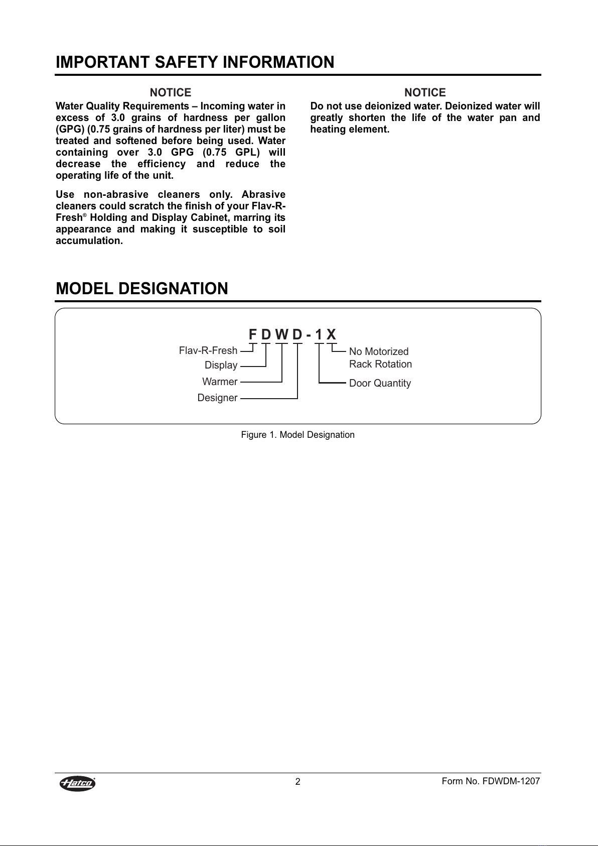
Model Designation ...............................................2
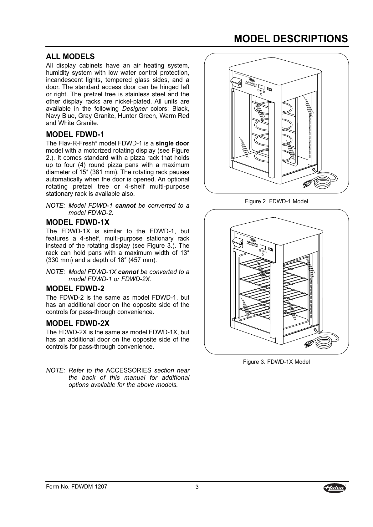
Model Descriptions..............................................3
Specifications.......................................................4
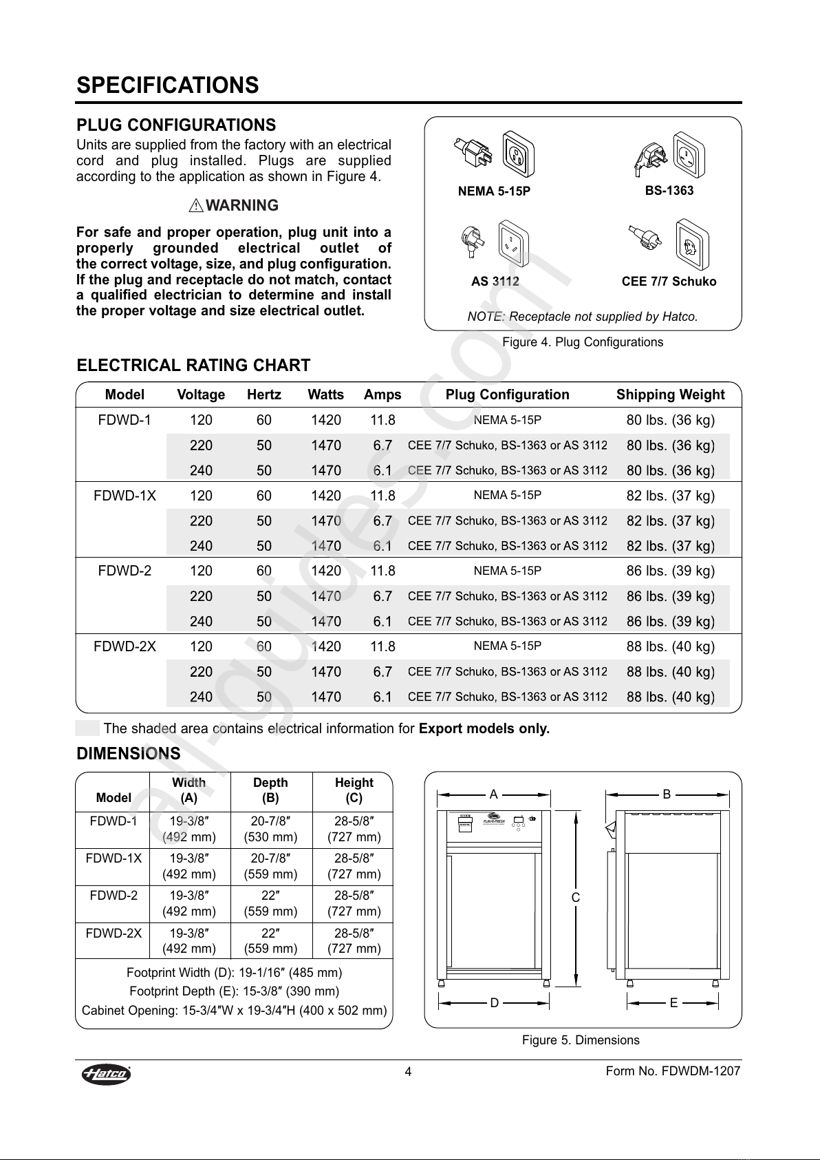
Plug Configurations.........................................4
Electrical Rating Chart ....................................4
Dimensions......................................................4
Installation ............................................................5
Unpacking .......................................................5
Location...........................................................5
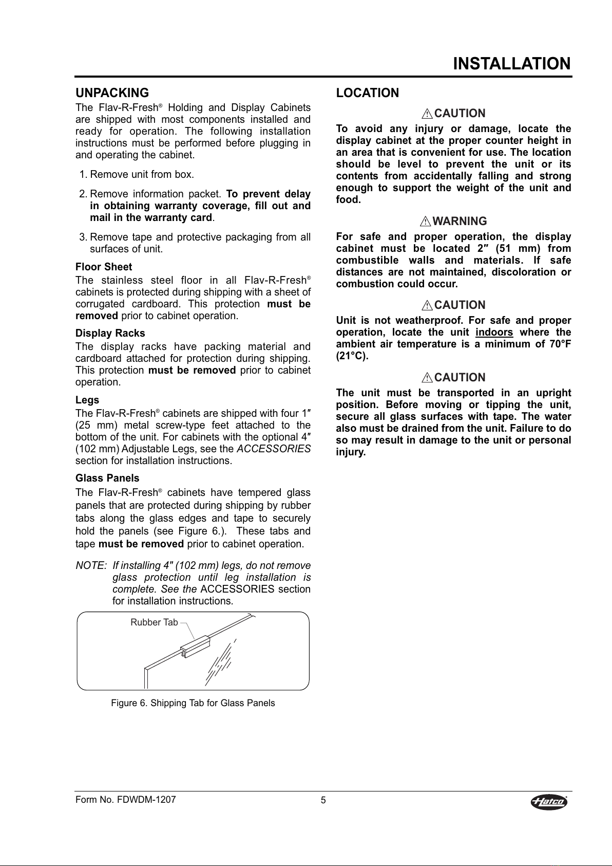
Reversible Access Door ..................................6
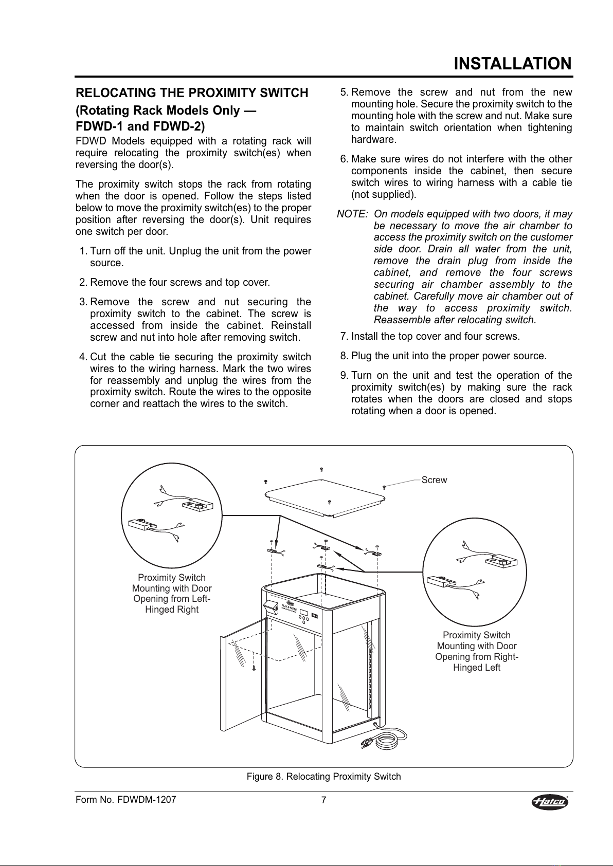
Relocating the Proximity Switch......................7
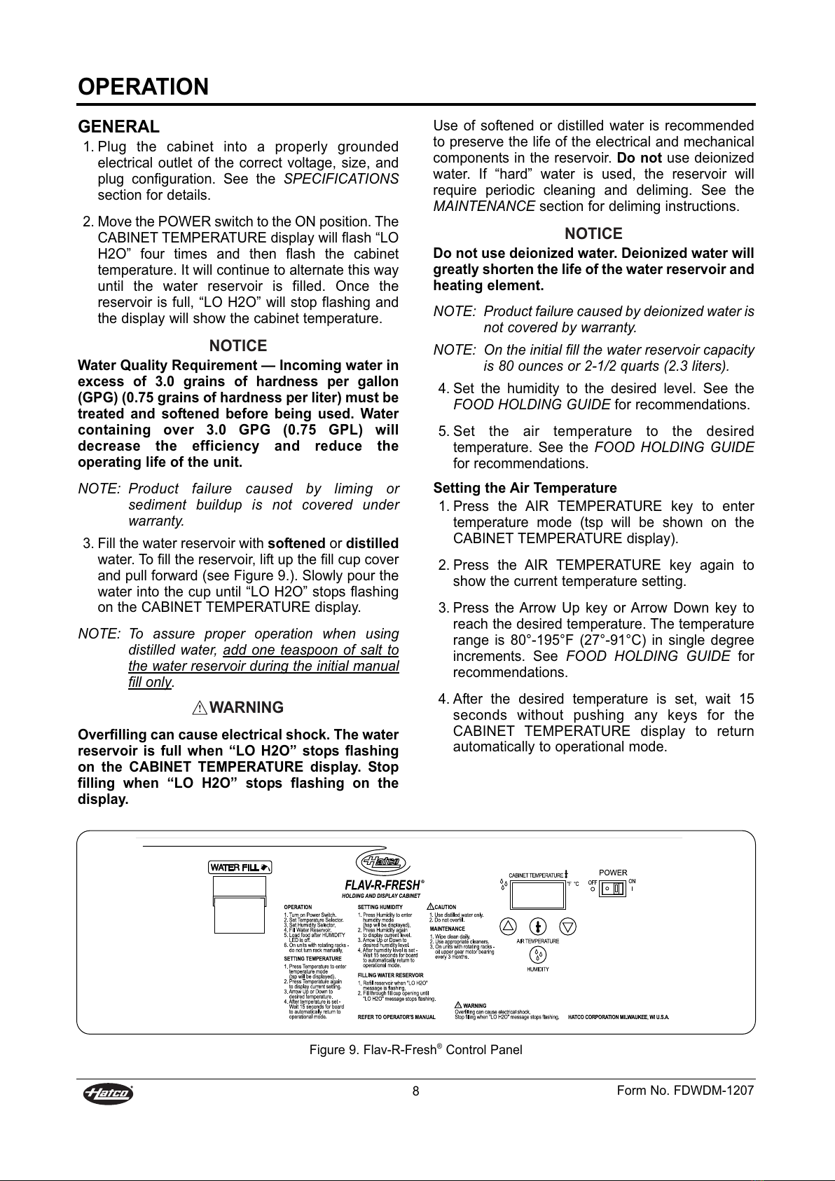
Operation ..............................................................8
General............................................................8
Food Holding Guide ........................................9
Maintenance .......................................................10
General..........................................................10
Cleaning ........................................................10
Draining The Reservoir .................................11
Removing Lime and Mineral Deposits ..........11
Display Light Bulb Replacement ...................12
Troubleshooting Guide......................................13
Accessories ........................................................15
Hatco imited Warranty.....................................17
Authorized Parts Distributors ............Back Cover
IMPORTANT OWNER INFORMATION
Record the model number, serial number
(identification decal located on the lower right hand
side, rear corner of the unit), voltage, and purchase
date of your Flav-R-Fresh®Holding and Display
Cabinet in the spaces provided. Please have this
information available when contacting Hatco for
service assistance.
Model No. ________________________________
Serial No. ________________________________
Voltage __________________________________
Date of Purchase __________________________
Business 8:00 a.m. to 5:00 p.m.
Hours: Central Standard Time
(Summer Hours: une to September –
8:00 a.m. to 5:00 p.m. C.S.T.
Monday through Thursday
8:00 a.m. to 2:30 p.m. C.S.T. Friday)
Telephone: (800) 558-0607; (414) 671-6350
Fax: (800) 690-2966 (Parts and Service)
(414) 671-3976 (International)
24 Hour 7 Day Parts and Service
Assistance available in the
United States and Canada
by calling (800) 558-0607.
Additional information can be found by visiting our
web site at www.hatcocorp.com.
INTRODUCTION
Hatco Flav-R-Fresh®Holding and Display Cabinets
are designed to hold prepared foods for prolonged
periods of time while maintaining that “just-made”
quality. Hatco Holding and Display Cabinets provide
the best environment for food products by regulating
the air temperature while at the same time balancing
the humidity level. The use of controlled,
moisturized heat maintains serving temperature and
food texture longer than conventional dry holding
equipment.
The Flav-R-Fresh®air flow pattern is designed
to maintain consistent cabinet temperature without
drying out foods. The precise combination of heat
and humidity creates a “blanket” effect around the
food. The air flow rate enables the cabinet to
recover temperature rapidly after opening and
closing the door.
This manual provides the installation, safety,
and operating instructions for the Flav-R-Fresh®
Holding and Display Cabinets. Hatco recommends
all installation, operating, and safety instructions
appearing in this manual be read prior to installation
or operation of your Hatco Holding and Display
Cabinet. Safety instructions that appear in this
manual after a safety alert symbol and the words
WARNING or CAUTION printed in boldface are very
important. WARNING means there is the
possibility of serious injury or death
to yourself or others. CAUTION means there
is the possibility of minor or moderate injury. The
word NOTICE signifies the possibility of equipment
or property damage only.
Hatco Flav-R-Fresh®Holding and Display Cabinets
are a product of extensive research and field testing.
The materials used were selected for maximum
durability, attractive appearance, and optimum
performance. Every unit is inspected
and tested thoroughly prior to shipment.
All manuals and user guides at all-guides.com

IMPORTANT SAFETY INFORMATION
Form No. FDWDM-1207 1
IMPORTANT! Read the following important safety information to avoid personal injury
or death, and to avoid damage to the equipment or property.
For safe and proper operation, plug unit into
a properly grounded electrical outlet of
the correct voltage, size, and plug
configuration. If the plug and receptacle do
not match, contact a qualified electrician to
determine and install the proper voltage and
size electrical outlet.
To avoid any injury, turn the POWER switch
OFF, unplug the unit from the power source,
and allow to cool completely before
performing any maintenance or cleaning.
Overfilling can cause electrical shock. The
water reservoir is full when “ O H2O” stops
flashing on the CABINET TEMPERATURE
display. Stop filling when “ O H2O” stops
flashing on the display.
To avoid any injury, turn the POWER switch
OFF and allow the unit to cool before
draining.
To prevent any injury, discontinue use if
power cord is frayed or worn.
To prevent any injury or damage to the unit,
do not pull unit by power cord.
To avoid any injury or damage, the unit
must be serviced by qualified personnel
only.
Only light bulbs that meet or exceed NSF
standards and are specifically designed for
food holding areas may be used. Breakage
of light bulbs not specially coated could
result in personal injury and/or food
contamination.
For safe and proper operation, the display
cabinet must be located 2″ (51 mm) from
combustible walls and materials. If safe
distances are not maintained, discoloration
or combustion could occur.
Holding food at temperatures less than
140°F (60°C) may be dangerous.
Temperatures under 140°F (60°C) promote
the growth of harmful bacteria and toxins in
some foods.
Hatco Corporation is not responsible for the
actual food product serving temperature. It
is the responsibility of the user to assure
that the food product is held and served at
a safe temperature.
WARNING
If service is required on this unit, contact
your Authorized Hatco Service Agent or
contact the Hatco Service Department at
800-558-0607 or 414-671-6350; fax 800-690-
2966; or International fax 414-671-3976.
This product has no “user-serviceable”
parts. To avoid damage to the unit or injury
to personnel, use only Authorized Hatco
Service Agents and Genuine Hatco
Replacement Parts when service is
required.
Genuine Hatco Replacement Parts are
specified to operate safely in the
environments in which they are used. Some
aftermarket or generic replacement parts do
not have the characteristics that will allow
them to operate safely in Hatco equipment.
It is essential to use Genuine Hatco
Replacement Parts when repairing Hatco
equipment. Failure to use Genuine Hatco
Replacement Parts may subject operators
of the equipment to hazardous electrical
voltage, resulting in electrical shock or
burn.
Some exterior surfaces on the display
cabinet will get hot. Use caution when
touching these areas to avoid injury.
To avoid any injury or damage, locate the
display cabinet at the proper counter height
in an area that is convenient for use. The
location should be level to prevent the unit
or its contents from accidentally falling and
strong enough to support the weight of the
unit and food.
Unit is not weatherproof. For safe and
proper operation, locate the unit indoors
where the ambient air temperature is a
minimum of 70°F (21°C).
The unit must be transported in an upright
position. Before moving or tipping the unit,
secure all glass surfaces with tape. The
water must be drained from the unit also.
Failure to do so may result in damage to the
unit or personal injury.
CAUTION
WARNING
All manuals and user guides at all-guides.com

2Form No. FDWDM-1207
IMPORTANT SAFETY INFORMATION
MODE DESIGNATION
Water Quality Requirements – Incoming water in
excess of 3.0 grains of hardness per gallon
(GPG) (0.75 grains of hardness per liter) must be
treated and softened before being used. Water
containing over 3.0 GPG (0.75 GP ) will
decrease the efficiency and reduce the
operating life of the unit.
Use non-abrasive cleaners only. Abrasive
cleaners could scratch the finish of your Flav-R-
Fresh®Holding and Display Cabinet, marring its
appearance and making it susceptible to soil
accumulation.
NOTICE
Do not use deionized water. Deionized water will
greatly shorten the life of the water pan and
heating element.
NOTICE
Figure 1. Model Designation
FDWD-1X
Flav-R-Fresh
Warmer
Display
Designer
Door Quantity
No Motorized
Rack Rotation
All manuals and user guides at all-guides.com

MODE DESCRIPTIONS
Form No. FDWDM-1207 3
A MODE S
All display cabinets have an air heating system,
humidity system with low water control protection,
incandescent lights, tempered glass sides, and a
door. The standard access door can be hinged left
or right. The pretzel tree is stainless steel and the
other display racks are nickel-plated. All units are
available in the following Designer colors: Black,
Navy Blue, Gray Granite, Hunter Green, Warm Red
and White Granite.
MODE FDWD-1
The Flav-R-Fresh®model FDWD-1 is a single door
model with a motorized rotating display (see Figure
2.). It comes standard with a pizza rack that holds
up to four (4) round pizza pans with a maximum
diameter of 15″ (381 mm). The rotating rack pauses
automatically when the door is opened. An optional
rotating pretzel tree or 4-shelf multi-purpose
stationary rack is available also.
NOTE: Model FDWD-1 cannot be converted to a
model FDWD-2.
MODE FDWD-1X
The FDWD-1X is similar to the FDWD-1, but
features a 4-shelf, multi-purpose stationary rack
instead of the rotating display (see Figure 3.). The
rack can hold pans with a maximum width of 13″
(330 mm) and a depth of 18″ (457 mm).
NOTE: Model FDWD-1X cannot be converted to a
model FDWD-1 or FDWD-2X.
MODE FDWD-2
The FDWD-2 is the same as model FDWD-1, but
has an additional door on the opposite side of the
controls for pass-through convenience.
MODE FDWD-2X
The FDWD-2X is the same as model FDWD-1X, but
has an additional door on the opposite side of the
controls for pass-through convenience.
NOTE: Refer to the ACCESSORIES section near
the back of this manual for additional
options available for the above models.
Figure 2. FDWD-1 Model
Figure 3. FDWD-1X Model
All manuals and user guides at all-guides.com

Width Depth Height
Model (A) (B) (C)
FDWD-1 19-3/8″ 20-7/8″ 28-5/8″
(492 mm) (530 mm) (727 mm)
FDWD-1X 19-3/8″ 20-7/8″ 28-5/8″
(492 mm) (559 mm) (727 mm)
FDWD-2 19-3/8″ 22″ 28-5/8″
(492 mm) (559 mm) (727 mm)
FDWD-2X 19-3/8″ 22″ 28-5/8″
(492 mm) (559 mm) (727 mm)
Model Voltage Hertz Watts Amps Plug Configuration Shipping Weight
FDWD-1 120 60 1420 11.8 NEMA 5-15P 80 lbs. (36 kg)
220 50 1470 6.7 CEE 7/7 Schuko, BS-1363 or AS 3112 80 lbs. (36 kg)
240 50 1470 6.1 CEE 7/7 Schuko, BS-1363 or AS 3112 80 lbs. (36 kg)
FDWD-1X 120 60 1420 11.8 NEMA 5-15P 82 lbs. (37 kg)
220 50 1470 6.7 CEE 7/7 Schuko, BS-1363 or AS 3112 82 lbs. (37 kg)
240 50 1470 6.1 CEE 7/7 Schuko, BS-1363 or AS 3112 82 lbs. (37 kg)
FDWD-2 120 60 1420 11.8 NEMA 5-15P 86 lbs. (39 kg)
220 50 1470 6.7 CEE 7/7 Schuko, BS-1363 or AS 3112 86 lbs. (39 kg)
240 50 1470 6.1 CEE 7/7 Schuko, BS-1363 or AS 3112 86 lbs. (39 kg)
FDWD-2X 120 60 1420 11.8 NEMA 5-15P 88 lbs. (40 kg)
220 50 1470 6.7 CEE 7/7 Schuko, BS-1363 or AS 3112 88 lbs. (40 kg)
240 50 1470 6.1 CEE 7/7 Schuko, BS-1363 or AS 3112 88 lbs. (40 kg)
4Form No. FDWDM-1207
SPECIFICATIONS
E ECTRICA RATING CHART
P UG CONFIGURATIONS
Units are supplied from the factory with an electrical
cord and plug installed. Plugs are supplied
according to the application as shown in Figure 4.
For safe and proper operation, plug unit into a
properly grounded electrical outlet of
the correct voltage, size, and plug configuration.
If the plug and receptacle do not match, contact
a qualified electrician to determine and install
the proper voltage and size electrical outlet.
WARNING
NEMA 5-15P
AS 3112 CEE 7/7 Schuko
BS-1363
Figure 4. Plug Configurations
FLAV-R-FRESH
HOLDING AND DISPLAY CABINET
A
DE
B
C
Figure 5. Dimensions
DIMENSIONS
Footprint Width (D): 19-1/16″ (485 mm)
Footprint Depth (E): 15-3/8″ (390 mm)
Cabinet Opening: 15-3/4″W x 19-3/4″H (400 x 502 mm)
The shaded area contains electrical information for Export models only.
NOTE: Receptacle not supplied by Hatco.
All manuals and user guides at all-guides.com
all-guides.com

INSTA ATION
Form No. FDWDM-1207 5
UNPACKING
The Flav-R-Fresh®Holding and Display Cabinets
are shipped with most components installed and
ready for operation. The following installation
instructions must be performed before plugging in
and operating the cabinet.
1. Remove unit from box.
2. Remove information packet. To prevent delay
in obtaining warranty coverage, fill out and
mail in the warranty card.
3. Remove tape and protective packaging from all
surfaces of unit.
Floor Sheet
The stainless steel floor in all Flav-R-Fresh®
cabinets is protected during shipping with a sheet of
corrugated cardboard. This protection must be
removed prior to cabinet operation.
Display Racks
The display racks have packing material and
cardboard attached for protection during shipping.
This protection must be removed prior to cabinet
operation.
egs
The Flav-R-Fresh®cabinets are shipped with four 1″
(25 mm) metal screw-type feet attached to the
bottom of the unit. For cabinets with the optional 4″
(102 mm) Adjustable Legs, see the ACCE ORIE
section for installation instructions.
Glass Panels
The Flav-R-Fresh®cabinets have tempered glass
panels that are protected during shipping by rubber
tabs along the glass edges and tape to securely
hold the panels (see Figure 6.). These tabs and
tape must be removed prior to cabinet operation.
NOTE: If installing 4″ (102 mm) legs, do not remove
glass protection until leg installation is
complete. ee the ACCESSORIES section
for installation instructions.
Figure 6. Shipping Tab for Glass Panels
Rubber Tab
OCATION
To avoid any injury or damage, locate the
display cabinet at the proper counter height in
an area that is convenient for use. The location
should be level to prevent the unit or its
contents from accidentally falling and strong
enough to support the weight of the unit and
food.
For safe and proper operation, the display
cabinet must be located 2″ (51 mm) from
combustible walls and materials. If safe
distances are not maintained, discoloration or
combustion could occur.
Unit is not weatherproof. For safe and proper
operation, locate the unit indoors where the
ambient air temperature is a minimum of 70°F
(21°C).
The unit must be transported in an upright
position. Before moving or tipping the unit,
secure all glass surfaces with tape. The water
also must be drained from the unit. Failure to do
so may result in damage to the unit or personal
injury.
CAUTION
CAUTION
CAUTION
WARNING
All manuals and user guides at all-guides.com

INSTA ATION
6Form No. FDWDM-1207
Striker Plate
Glass Door
Hinge Pin Screw
and Nylon Washers
Hinge Pin Screw
and Nylon Washer
Hinge Assembly
Figure 7. Reversible Access Door
REVERSIB E ACCESS DOOR
The Flav-R-Fresh®access door may be hinged on
either the left or right side for your convenience (see
Figure 7.). Use the following procedure to reverse
the door hinges.
1. Remove the top hinge pin screw holding the door
to the hinge. Remove the nylon washer.
2. Tip the door assembly forward (away from
cabinet) and lift gently to clear the bottom hinge
assembly. Remove the two nylon washers.
3. Reinstall the hinge pin screw that was removed
in Step 1.
4. Remove the screws holding the hinges to the
cabinet.
5. Remove the screws from the striker plates on the
non-hinge side of the cabinet.
6. Install the striker plates on the opposite side of
the cabinet where the hinges were previously
mounted.
7. Install the hinges on the opposite side of the
cabinet where the striker plates were previously
mounted using the original hinge mounting
screws.
8. Carefully rotate the door 180°.
9. Remove the hinge pin screw from the end that is
now the top.
10.Carefully place the door assembly with the two
nylon washers into the bottom hinge.
11.Tip/tilt the door assembly towards the cabinet
and align the door top with the hinge. With the
nylon washer between the door top and the
hinge, reinstall the door hinge pin screw through
the hinge and into the door top.
All manuals and user guides at all-guides.com

INSTA ATION
Form No. FDWDM-1207 7
RE OCATING THE PROXIMITY SWITCH
(Rotating Rack Models Only —
FDWD-1 and FDWD-2)
FDWD Models equipped with a rotating rack will
require relocating the proximity switch(es) when
reversing the door(s).
The proximity switch stops the rack from rotating
when the door is opened. Follow the steps listed
below to move the proximity switch(es) to the proper
position after reversing the door(s). Unit requires
one switch per door.
1. Turn off the unit. Unplug the unit from the power
source.
2. Remove the four screws and top cover.
3. Remove the screw and nut securing the
proximity switch to the cabinet. The screw is
accessed from inside the cabinet. Reinstall
screw and nut into hole after removing switch.
4. Cut the cable tie securing the proximity switch
wires to the wiring harness. Mark the two wires
for reassembly and unplug the wires from the
proximity switch. Route the wires to the opposite
corner and reattach the wires to the switch.
Proximity Switch
Mounting with Door
Opening from Left-
Hinged Right
Proximity Switch
Mounting with Door
Opening from Right-
Hinged Left
Screw
Figure 8. Relocating Proximity Switch
5. Remove the screw and nut from the new
mounting hole. Secure the proximity switch to the
mounting hole with the screw and nut. Make sure
to maintain switch orientation when tightening
hardware.
6. Make sure wires do not interfere with the other
components inside the cabinet, then secure
switch wires to wiring harness with a cable tie
(not supplied).
NOTE: On models equipped with two doors, it may
be necessary to move the air chamber to
access the proximity switch on the customer
side door. Drain all water from the unit,
remove the drain plug from inside the
cabinet, and remove the four screws
securing air chamber assembly to the
cabinet. Carefully move air chamber out of
the way to access proximity switch.
Reassemble after relocating switch.
7. Install the top cover and four screws.
8. Plug the unit into the proper power source.
9. Turn on the unit and test the operation of the
proximity switch(es) by making sure the rack
rotates when the doors are closed and stops
rotating when a door is opened.
All manuals and user guides at all-guides.com

OPERATION
8Form No. FDWDM-1207
Figure 9. Flav-R-Fresh®Control Panel
GENERA
1. Plug the cabinet into a properly grounded
electrical outlet of the correct voltage, size, and
plug configuration. See the PECIFICATION
section for details.
2. Move the POWER switch to the ON position. The
CABINET TEMPERATURE display will flash “LO
H2O” four times and then flash the cabinet
temperature. It will continue to alternate this way
until the water reservoir is filled. Once the
reservoir is full, “LO H2O” will stop flashing and
the display will show the cabinet temperature.
Water Quality Requirement — Incoming water in
excess of 3.0 grains of hardness per gallon
(GPG) (0.75 grains of hardness per liter) must be
treated and softened before being used. Water
containing over 3.0 GPG (0.75 GP ) will
decrease the efficiency and reduce the
operating life of the unit.
NOTE: Product failure caused by liming or
sediment buildup is not covered under
warranty.
3. Fill the water reservoir with softened or distilled
water. To fill the reservoir, lift up the fill cup cover
and pull forward (see Figure 9.). Slowly pour the
water into the cup until “LO H2O” stops flashing
on the CABINET TEMPERATURE display.
NOTE: To assure proper operation when using
distilled water, add one teaspoon of salt to
the water reservoir during the initial manual
fill only.
Overfilling can cause electrical shock. The water
reservoir is full when “ O H2O” stops flashing
on the CABINET TEMPERATURE display. Stop
filling when “ O H2O” stops flashing on the
display.
NOTICE
WARNING
Use of softened or distilled water is recommended
to preserve the life of the electrical and mechanical
components in the reservoir. Do not use deionized
water. If “hard” water is used, the reservoir will
require periodic cleaning and deliming. See the
MAINTENANCE section for deliming instructions.
Do not use deionized water. Deionized water will
greatly shorten the life of the water reservoir and
heating element.
NOTE: Product failure caused by deionized water is
not covered by warranty.
NOTE: On the initial fill the water reservoir capacity
is 80 ounces or 2-1/2 quarts (2.3 liters).
4. Set the humidity to the desired level. See the
FOOD HOLDING GUIDE for recommendations.
5. Set the air temperature to the desired
temperature. See the FOOD HOLDING GUIDE
for recommendations.
Setting the Air Temperature
1. Press the AIR TEMPERATURE key to enter
temperature mode (tsp will be shown on the
CABINET TEMPERATURE display).
2. Press the AIR TEMPERATURE key again to
show the current temperature setting.
3. Press the Arrow Up key or Arrow Down key to
reach the desired temperature. The temperature
range is 80°-195°F (27°-91°C) in single degree
increments. See FOOD HOLDING GUIDE for
recommendations.
4. After the desired temperature is set, wait 15
seconds without pushing any keys for the
CABINET TEMPERATURE display to return
automatically to operational mode.
NOTICE
All manuals and user guides at all-guides.com

OPERATION
Form No. FDWDM-1207 9
Setting the Humidity evel
1. Press the HUMIDITY key to enter humidity mode
(hsp will be shown on the CABINET
TEMPERATURE display).
2. Press the HUMIDITY key again to show the
current humidity level.
3. Press the Arrow Up key or Arrow Down key to
reach the desired humidity level. Humidity range
is 1 through 5 (1 is the lowest amount of humidity
and 5 is the highest). See FOOD HOLDING
GUIDE for recommendations.
4. After the desired humidity level is set, wait 15
seconds without pushing any keys for the
CABINET TEMPERATURE display to return
automatically to operational mode.
NOTE: Temperature and humidity settings may
vary depending upon product make-up and
consistency. The CABINET
TEMPERATURE display shows the lowest
temperature point inside the cabinet, not the
product temperature.
Allow 20 minutes to preheat a full reservoir of water.
The Flav-R-Fresh®is then ready to hold foods at the
humidity and temperature selected.
The reservoir capacity permits uninterrupted
operation for approximately 3-6 hours, depending
on the settings and how frequently the door is
opened. When “LO H2O” is flashing on the
CABINET TEMPERATURE display, add water to the
reservoir. The water reservoir refill capacity is
approximately 64 ounces, or two (2) quarts
(1.9 liters).
Overfilling can cause electrical shock. The water
reservoir is full when “ O H2O” stops flashing
on the CABINET TEMPERATURE display. Stop
filling when “ O H2O” stops flashing on the
display.
Some exterior surfaces on the display cabinet
will get hot. Use caution when touching these
areas to avoid injury.
To prevent any injury, discontinue use if power
cord is frayed or worn.
To prevent any injury or damage to the unit, do
not pull unit by power cord.
Hatco Corporation is not responsible for the
actual food product serving temperature. It is
the responsibility of the user to ensure that the
food product is held and served at a safe
temperature.
Holding food at temperatures less than 140°F
(60°C) may be dangerous. Temperatures under
140°F (60°C) promote the growth of harmful
bacteria and toxins in some foods.
WARNING
WARNING
WARNING
WARNING
CAUTION
WARNING
Maximum Humidity Temperature
Type of Food Holding Time Setting °F °C
Biscuits 4 Hours 4 130 55
Chicken Pieces (Fried) 4 Hours 5 175 80
Croissants 4 Hours 1 140 60
Fruit Pies 3-1/2 Hours 4 140 60
Onion Rings 1/2 to 1 Hour 1 175 80
Pizza — Thick Crust 1 Hour 4 185 85
Thin Crust 1 Hour 5 180 82
Pretzels 3 Hours 4 140 60
Wrapped Sandwiches 2 Hours 4 180 82
FOOD HO DING GUIDE
NOTE: All times and settings are recommendations only and may vary depending on product preparation,
cooking time and internal food temperature.
All manuals and user guides at all-guides.com
all-guides.com

MAINTENANCE
10 Form No. FDWDM-1207
GENERA
The Hatco Flav-R-Fresh®Holding and Display
Cabinets are designed for maximum durability and
performance with minimum maintenance. The rack
motor and blower motor are permanently lubricated
and require no maintenance.
C EANING
To prevent electric shock or injury, turn the
POWER switch OFF, unplug the unit from the
power source and allow to cool completely
before performing any maintenance or cleaning.
To prevent any injury, discontinue use if power
cord is frayed or worn.
Hatco Flav-R-Fresh®cabinets are made of stainless
steel and aluminum. To preserve the bright finish, it
is recommended that the exterior and interior
surfaces be wiped daily with a damp cloth. Food
pans should be removed and washed. Stubborn
stains may be removed with a good stainless steel
cleaner or a non-abrasive cleaner.
Use non-abrasive cleaners only. Abrasive
cleaners could scratch the finish of your Flav-R-
Fresh®Holding and Display Cabinet marring its
appearance and making it susceptible to soil
accumulation.
Clean the glass sides using a common glass
cleaner. For hard-to-clean stains, removal of the
glass is suggested.
RemovIng the Glass
1. Lift the glass to be cleaned out of the bottom
channel of the cabinet.
2. Pull the lower edge away from the cabinet.
3. Carefully lower the glass until the top clears the
cabinet.
Replacing the Glass
1. Position the glass with the top edge under the
cabinet lip and raise the glass until it clears the
bottom channel of the cabinet.
2. Move the bottom of the glass towards the cabinet
until the glass rests against the cabinet frame.
3. Carefully lower the glass until it rests in the
bottom channel of the cabinet.
NOTICE
WARNING
WARNING
Removing the Rotating Rack for Cleaning
(Models FDWD-1 and FDWD-2)
1. Open the front access door.
2. Remove the two (2) connecting pins from the
connecting coupling located at the top of the rack
inside the cabinet (see Figure 10.).
3. Lower the connecting coupling until it is free of
the motor shaft and remove the rack from the
cabinet.
Figure 10. Removing Motorized Display Racks
Replacing the Rotating Rack
1. With the connecting coupling in position on the
top rack shaft, insert the rack into the cabinet
through the access door and place the rack
bottom point in the dimple located at the center
of the cabinet floor.
2. Slide the connecting coupling up onto the motor
shaft and align the coupling holes.
3. Insert the two (2) connecting pins. The top
connecting pin goes through the connecting
coupling and the motor shaft. The bottom
connecting pin goes through the connecting
coupling and the rack shaft.
Connecting
Pin
Bottom
Point
Connecting
Coupling
Rack
Shaft
All manuals and user guides at all-guides.com

MAINTENANCE
Form No. FDWDM-1207 11
DRAINING THE RESERVOIR
To avoid any injury, turn the power OFF to the
unit and allow to cool before draining.
It is recommended that the Flav-R-Fresh®water
reservoir be drained prior to moving the cabinet and
after removing lime or mineral deposits from the
water reservoir.
To drain the reservoir, locate the valve on the
underside of the ceiling sheet. Position a one gallon
(four liter) container under the valve. Turn the valve
handle from the horizontal position (closed) to the
vertical position (open). Once the reservoir is empty,
return handle to the closed position.
Figure 11. Draining Reservoir Valve
NOTE: If the water used has an excessive amount
of lime or mineral content, follow the
REMOVING LIME AND MINERAL
DEPO IT procedure for periodic cleaning
and deliming of the water reservoir.
Water Quality Requirement — Incoming water in
excess of 3.0 grains of hardness per gallon
(GPG) (0.75 grains of hardness per liter) must be
treated and softened before being used. Water
containing over 3.0 GPG (0.75 GP ) will
decrease the efficiency and reduce the
operating life of the unit.
NOTE: Product failure caused by liming or
sediment buildup is not covered under
warranty.
Valve
Open
Valve
Closed
NOTICE
WARNING
REMOVING IME AND MINERA
DEPOSITS
1. Turn off the unit and unplug the unit from its
power source.
2. After the unit has cooled down, drain all
remaining water out of the unit.
3. Fill the unit with a mixture of 75% water and 25%
off-the-shelf vinegar.
NOTE: It is recommended that this procedure be
performed when the unit will not by used for
a period of time, such as the end of the day.
4. Plug the unit into the correct power source and
turn on the unit.
5. With both the humidity and heat settings on high,
allow the unit to run for 30 minutes.
6. After the deliming period, turn off the unit, unplug
it from the power source, and allow it to cool
7. Drain the solution from the unit (refer to the
DRAINING THE RE ERVOIR procedure).
8. Continue to fill and drain the unit with water until
the discharge is clear and all deliming solution
has been removed and rinsed through.
9. Plug the cabinet power cord into its power source
and fill the unit as usual for daily operation.
NOTE: The lime and mineral content of the water
used for daily operation will determine how
often this procedure must be performed.
All manuals and user guides at all-guides.com

MAINTENANCE
12 Form No. FDWDM-1207
DISP AY IGHT BU B REP ACEMENT
The display light is an incandescent bulb that
illuminates the warming area. This bulb has a
special coating to guard against injury and food
contamination in the event of breakage.
To replace a bulb, disconnect the power supply and
wait until the unit has cooled. Display lamps have a
threaded base. Unscrew the bulb from the unit and
replace it with a new specially coated incandescent
bulb. Hatco shatter-resistant bulbs meet NSF
standards for food holding and display areas. For
120 Volt applications, use Hatco part number
02.30.043.00. For 220 or 240 Volt applications, use
Hatco part number 02.30.058.00.
Only light bulbs that meet or exceed NSF
standards and that are specifically designed for
food holding areas may be used. Breakage of
light bulbs not specially coated could result in
personal injury and/or food contamination.
If service is required on this unit, contact your
Authorized Hatco Service Agent, or contact the
Hatco Service Department at 800-558-0607 or
414-671-6350; fax 800-690-2966; or International
fax 414-671-3976.
WARNING
WARNING
This product has no “user-serviceable” parts. To
avoid damage to the unit or injury to personnel,
use only Authorized Hatco Service Agents and
Genuine Hatco Replacement Parts when service
is required.
Genuine Hatco Replacement Parts are specified
to operate safely in the environments in which
they are used. Some aftermarket or generic
replacement parts do not have the
characteristics that will allow them to operate
safely in Hatco equipment. It is essential to use
Genuine Hatco Replacement Parts when
repairing Hatco equipment. Failure to use
Genuine Hatco Replacement Parts may subject
operators of the equipment to hazardous
electrical voltage resulting in electrical shock or
burn.
WARNING
WARNING
All manuals and user guides at all-guides.com

TROUB ESHOOTING GUIDE
Form No. FDWDM-1207 13
SYMPTOM PROBAB E CAUSE CORRECTIVE ACTION
Unit is operational, but
revolving rack (if so
equipped) does not turn.
Unit is plugged in, but
nothing works.
No power to unit.
Power cord connections are
loose or disconnected.
Power cord is damaged.
Defective ON/OFF switch.
Check electrical receptacle and verify
that power supply matches specifications
on unit. If receptacle is not working, check
circuit breaker and reset, or plug unit into
a different known working receptacle.
Contact Authorized Service Agent or
Hatco for assistance.
Contact Authorized Service Agent or
Hatco for assistance.
Contact Authorized Service Agent or
Hatco for assistance.
Incorrect voltage is supplied
to rack motor.
Proximity magnet or proximity
switch not working properly.
Contact Authorized Service Agent or
Hatco for assistance.
Contact Authorized Service Agent or
Hatco for assistance.
To avoid any injury or damage, the unit must be
serviced by qualified personnel only.
WARNING
To prevent electric shock or injury, turn the
POWER switch OFF, unplug the unit from the
power source, and allow to cool completely
before performing any maintenance or cleaning.
WARNING
Unit is energized, but display
lights do not work.
Unit operates, but is not
circulating air inside cabinet.
Light bulb is burned out or
loose.
Blower wires are loose or
disconnected.
The correct voltage may not
be supplied to blower.
Check light bulb. If burned out, replace. If
loose, tighten.
Contact Authorized Service Agent or
Hatco for assistance.
Contact Authorized Service Agent or
Hatco for assistance.
NOTE: TROUBLE HOOTING GUIDE continued on next page.
All manuals and user guides at all-guides.com

TROUB ESHOOTING GUIDE
14 Form No. FDWDM-1207
SYMPTOM PROBAB E CAUSE CORRECTIVE ACTION
Unit is not producing any
“hot air” inside cabinet.
Unit is heating, but is not
producing humidity inside
cabinet. Low water light is off,
and unit is full of water.
Unit is heating, but is not
producing humidity inside
cabinet. Low water light is on
and unit is full of water.
Safety high-limit is tripped or
open.
Incorrect voltage supplied to
heating element.
Blower motor is not working.
Incorrect voltage supplied to
water heating element or
heating element is defective.
When using distilled water, no
minerals are being sensed by
low water probe.
Low water protection system is
malfunctioning.
Contact Authorized Service Agent or
Hatco for assistance.
Contact Authorized Service Agent or
Hatco for assistance.
Check blower motor - refer to Symptom
“Unit operates, but is not circulating air
inside cabinet.”
Contact Authorized Service Agent or
Hatco for assistance.
On initial fill, add one teaspoon of salt to
the water reservoir.
Contact Authorized Service Agent or
Hatco for assistance.
All manuals and user guides at all-guides.com
all-guides.com

ACCESSORIES
Form No. FDWDM-1207 15
4″ (102 MM) ADJUSTAB E EGS
The 4″ (102 mm) adjustable legs are used to add
additional height to the unit.
1. Secure all glass sides and doors with tape. Lay
the unit on it’s side.
2. Remove the four 1″ (25 mm) metal screw type
feet.
3. Remove leg bracket hardware, and align the new
leg bracket (part number 04.24.235.00) over
existing bracket. Secure to the cabinet with the
previously removed hardware.
Figure 12. Installation of Leg Bracket
4. Screw the 4″ (102 mm) legs into the holes
provided. After all the legs are tightened, return
the unit to its upright position. If the unit is not
level or rocks, turn the adjustable tip of the
appropriate leg to correct the condition.
(See Figure 13.)
Figure 13. Installing and Leveling Legs
Lengthen
Shorten
Adjustable
Tip
Bracket
Part Number
04.24.235.00
DISP AY RACKS
A nickel-plated 4-tier circle rack, a nickel-plated
4-shelf multi-purpose rack, a nickel-plated 4-shelf
angle rack, and a stainless steel pretzel tree are
available to “customize” Flav-R-Fresh®to your
foodservice operation (see Figure 14.).
Figure 14. Display Racks
Motorless Rack Coupling
The motorless rack coupling allows
the stationary installation of a 4-tier
circle rack or 3-tier pretzel tree in
cabinets that do not have a rack
motor (FDWD-1X and FDWD-2X).
Motorless
Rack Coupling
4-Tier Circle Rack*
Model FDWD4TCR
3-1/4” (82 mm) opening
between racks.
Max. 15” diameter
pans.
4-Shelf Angle Rack
Model FDWD4SAR
3-3/4” (95 mm) opening
between shelves.
4-Shelf
Multi-Purpose Rack
Model FDWD4SMP
3-1/2” (89 mm) opening
between shelves.
1st and 3rd shelves
are removable.
3-Tier Pretzel Tree*
Model FDWD3TPT
5-7/8” (149 mm) opening
between racks.
*Racks designed for use with motorized display.
All manuals and user guides at all-guides.com

ACCESSORIES
16 Form No. FDWDM-1207
MERCHANDISING DECA
Self-adhesive merchandising decals are available to
promote your food products. The decals are
designed to be installed on three (3) sides of the
cabinet above the glass panels. Merchandising
decals are red with yellow letters reading HOT
PIZZA or HOT PRETZELS. A graphic decal
featuring pizza illustrations is also available.
Decal Installation (See Figure 15)
1. Before installing decals, clean the side panels
with a non-oily cleaner, such as isopropyl alcohol
(rubbing alcohol).
2. After the cleaned surfaces have dried, remove
the protective backing from the decal and apply
to the panel.
3. Any air pockets or bubbles behind the sticker can
be removed by rubbing gently with a soft cloth
from the center towards the outer edges.
Figure 15. Decal Installation
SIGN HO DERS
Use the following procedures to install either the
Three-Piece Sign Holder or the One-Piece Sign
Holder.
NOTE: ignage not supplied by Hatco. ign
dimensions 19-1/16″ w (484 mm) x 3-1/4″ h
(83 mm) x 1/16″ l (2 mm).
To avoid any injury, turn the POWER switch OFF,
unplug the unit from the power source, and
allow to cool completely before performing any
maintenance or cleaning.
Three-Piece Sign Holder Installation
(See Figure 16)
1. Remove the four hood mounting screws from the
cabinet hood.
2. Align the two sign holder side pieces over the
mounting holes for the cabinet hood.
3. Reinsert the two front hood mounting screws
through the holes in the front (control side) of the
two sign holder side pieces and into the cabinet
hood. DO NOT tighten.
WARNING
Decal
4. Align the holes in the sign holder rear piece with
the holes in the sign holder side pieces and the
holes in the cabinet hood.
5. Reinsert the two rear hood mounting screws
through the sign holder rear piece, the sign
holder side pieces and into the cabinet hood.
6. Tighten all screws.
7. Place the polycarbonate window(s) into sign
holder.
Figure 16. Three-Piece Sign Holder Installation
One-Piece Sign Holder Installation
(See Figure 17)
NOTE: The One-Piece ign Holder is available on
FDWD-1 and FDWD-1X models only.
1. Remove the four hood mounting screws from the
cabinet hood.
2. Remove the existing cabinet hood.
3. Place the new cabinet hood/sign holder
assembly over the mounting holes.
4. Reinsert the four hood mounting screws through
the holes in the cabinet hood/sign holder
assembly and into the cabinet.
5. Tighten all screws.
Figure 17. One-Piece Sign Holder Installation
Hood Mounting
Screw
One Piece
Sign Holder
Cabinet
Hood
Hood Mounting
Screw
Three-Piece
Sign Holder
Cabinet
Hood
All manuals and user guides at all-guides.com

HATCO IMITED WARRANTY
Form No. FDWDM-1207 17
1. PRODUCT WARRANTY
Hatco warrants the products that it manufactures
(the “Products”) to be free from defects in
materials and workmanship, under normal
use and service, for a period of one (1) year from
the date of purchase when installed and
maintained in accordance with Hatco’s written
instructions or 18 months from the date of
shipment from Hatco. Buyer must establish the
product’s purchase date by returning Hatco’s
Warranty Registration Card or by other means
satisfactory to Hatco in its sole discretion.
Hatco warrants the following Product components
to be free from defects in materials and
workmanship from the date of purchase (subject
to the foregoing conditions) for the period(s) of
time and on the conditions listed below:
a) One (1) Year Parts and abor P US One
(1) Additional Year Parts-Only Warranty:
Toaster Elements (metal sheathed)
Drawer Warmer Elements (metal sheathed)
Drawer Warmer Drawer Rollers and Slides
Food Warmer Elements (metal sheathed)
Display Warmer Elements (metal sheathed
air heating)
Holding Cabinet Elements (metal sheathed
air heating)
Built-In Heated Well Elements
(metal sheathed)
b) One (1) Year Parts and abor P US Four
(4) Years Parts-Only Warranty on
pro-rated terms that Hatco will explain
at Buyer’s request:
3CS and FR Tanks
c) One (1) Year Parts and abor P US Nine
(9) Years Parts-Only Warranty on:
Electric Booster Heater Tanks
Gas Booster Heater Tanks
THE FOREGOING WARRANTIES ARE
EXCLUSIVE AND IN LIEU OF ANY OTHER
WARRANTY, EXPRESSED OR IMPLIED,
INCLUDING BUT NOT LIMITED TO ANY
IMPLIED WARRANTY OF MERCHANTABILITY
OR FITNESS FOR A PARTICULAR PURPOSE
OR PATENT OR OTHER INTELLECTUAL
PROPERTY RIGHT INFRINGEMENT. Without
limiting the generality of the foregoing, SUCH
WARRANTIES DO NOT COVER: Coated
incandescent light bulbs, fluorescent lights, lamp
warmer heat bulbs, glass components, Product
failure in booster tank, fin tube heat exchanger, or
other water heating equipment, caused
by liming, sediment buildup, chemical attack or
freezing, Product misuse, tampering or
misapplication, improper installation, or application
of improper voltage.
2. IMITATION OF REMEDIES AND
DAMAGES
Hatco’s liability and Buyer’s exclusive remedy
hereunder will be limited solely, at Hatco’s option,
to repair or replacement by a Hatco-authorized
service agency (other than where Buyer is
located outside of the United States, Canada,
United Kingdom or Australia in which case
Hatco’s liability and Buyer’s exclusive remedy
hereunder will be limited solely to replacement of
part under warranty) with respect to any claim
made within the applicable warranty period
referred to above. Hatco reserves the right to
accept or reject any such claim in whole or in part.
Hatco will not accept the return of any Product
without prior written approval from Hatco, and all
such approved returns shall be made at Buyer’s
sole expense. HATCO WILL NOT BE LIABLE,
UNDER ANY CIRCUMSTANCES, FOR
CONSEQUENTIAL OR INCIDENTAL
DAMAGES, INCLUDING BUT NOT LIMITED TO
LABOR COSTS OR LOST PROFITS
RESULTING FROM THE USE OF OR INABILITY
TO USE THE PRODUCTS OR FROM THE
PRODUCTS BEING INCORPORATED IN OR
BECOMING A COMPONENT OF ANY OTHER
PRODUCT OR GOODS.
All manuals and user guides at all-guides.com

Printed in U.S.A. December 2007 Parts No. 07.04.406.00 Form No. FDWM-1207
HATCO CORPORATION
P.O. Box 340500, Milwaukee, WI 53234-0500 U.S.A.
(800) 558-0607 (414) 671-6350
Parts and Service Fax (800) 690-2966
International Fax (414) 671-3976
www.hatcocorp.com
HATCO AUTHORIZED PARTS DISTRIBUTORS
A ABAMA
ones McLeod Appl. Svc.
Birmingham 205-251-0159
ARIZONA
Auth. Comm. Food Equip.
Phoenix 602-234-2443
Byassee Equipment Co.
Phoenix 602-252-0402
CA IFORNIA
Industrial Electric
Commercial Parts & Service, Inc.
Huntington Beach 714-379-7100
Chapman Appl. Service
San Diego 619-298-7106
P & D Appliance
Commercial Parts & Service, Inc.
S. San Francisco 650-635-1900
CO ORADO
Hawkins Commercial Appliance
Englewood 303-781-5548
F ORIDA
Whaley Foodservice Repair
acksonville 904-725-7800
Nass Service Co., Inc.
Orlando 407-425-2681
B.G.S.I.
Pompano Beach 954-971-0456
Comm. Appliance Service
Tampa 813-663-0313
GEORGIA
TWC Services
Smyrna 770-438-9797
Heritage Service Group
Norcross 866-388-9837
Southeastern Rest. Svc.
Norcross 770-446-6177
HAWAII
Burney’s Comm. Service, Inc.
Honolulu 808-848-1466
Food Equip Parts & Service
Honolulu 808-847-4871
I INOIS
Parts Town
Lombard 708-865-7278
Eichenauer Elec. Service
Decatur 217-429-4229
Midwest Elec. Appl. Service
Elmhurst 630-279-8000
Cone’s Repair Service
Moline 309-797-5323
INDIANA
GCS Service
Indianapolis 317-545-9655
IOWA
Electric Motor Service Co.
Davenport 319-323-1823
Goodwin Tucker Group
Des Moines 515-262-9308
KENTUCKY
Certified Service Center
Lexington 859-254-8854
Certified Service Center
Louisville 502-964-7007
OUISIANA
Chandlers Parts & Service
Baton Rouge 225-272-6620
MARY AND
Electric Motor Service
Baltimore 410-467-8080
GCS Service
Silver Spring 301-585-7550
MASSACHUSETTS
Ace Service Co., Inc.
Needham 781-449-4220
MICHIGAN
Commercial Kitchen Service
Bay City 517-893-4561
Bildons Appliance Service
Detroit 248-478-3320
Midwest Food Equip. Service
Grandville 616-261-2000
MINNESOTA
GCS Service
Minneapolis 612-546-4221
MISSOURI
General Parts
Kansas City 816-421-5400
Commercial Kitchen Services
St. Louis 314-890-0700
Kaemmerlen Parts & Service
St. Louis 314-535-2222
NEBRASKA
Anderson Electric
Omaha 402-341-1414
NEVADA
Burney’s Commercial
Las Vegas 702-736-0006
Hi. Tech Commercial Service
N. Las Vegas 702-649-4616
NEW JERSEY
ay Hill Repair
Fairfield 973-575-9145
Service Plus
Flanders 973-691-6300
NEW YORK
Acme American Repairs, Inc.
Brooklyn 718-456-6544
Alpro Service Co.
Brooklyn 718-386-2515
Appliance Installation
Buffalo 716-884-7425
Northern Parts Dist.
Plattsburgh 518-563-3200
.B. Brady, Inc.
Syracuse 315-422-9271
NORTH CARO INA
Authorized Appliance
Charlotte 704-377-4501
OHIO
Akron/Canton Comm. Svc. Inc.
Akron 330-753-6635
Certified Service Center
Cincinnati 513-772-6600
Commercial Parts and Service
Columbus 614-221-0057
Electrical Appl. Repair Service
Independence 216-459-8700
E. A. Wichman Co.
Toledo 419-385-9121
OK AHOMA
Hagar Rest. Service, Inc.
Oklahoma City 405-235-2184
Krueger, Inc.
Oklahoma City 405-528-8883
OREGON
Ron’s Service, Inc.
Portland 503-624-0890
PENNSY VANIA
Elmer Schultz Services
Philadelphia 215-627-5401
FAST Comm. Appl. Service
Philadelphia 215-288-4800
Appliance Installation & Service
Pittsburgh 412-809-0244
K & D Service Co.
Harrisburg 717-236-9039
Electric Repair Co.
Reading 610-376-5444
RHODE IS AND
Marshall Electric Co.
Providence 401-331-1163
SOUTH CARO INA
Whaley Foodservice Repair
W. Columbia 803-791-4420
TENNESSEE
Camp Electric
Memphis 901-527-7543
TEXAS
GCS Service
Fort Worth 817-831-0381
Armstrong Repair Service
Houston 713-666-7100
Commercial Kitchen Repair Co.
San Antonio 210-735-2811
UTAH
La Monica’s Rest. Equip. Service
Murray 801-263-3221
VIRGINIA
Daubers
Norfolk 757-855-4097
Daubers
Springfield 703-866-3600
WASHINGTON
Restaurant Appl. Service
Seattle 206-524-8200
WISCONSIN
A.S.C., Inc.
Madison 608-246-3160
A.S.C., Inc.
Milwaukee 414-543-6460
CANADA
A BERTA
Key Food Equipment Service
Edmonton 780-438-1690
BRITISH CO UMBIA
Key Food Equipment Service
Vancouver 604-433-4484
MANITOBA
Air Rite, Inc.
Winnepeg 204-895-2300
NEW BRUNSWICK
EMR Services, Ltd.
Moncton 506-855-4228
ONTARIO
R.G. Henderson Ltd.
Toronto 416-422-5580
Choquette CKS
Ottawa 613-739-8458
QUEBEC
Choquette CKS
Montreal 514-722-2000
Choquette CKS
Québec City 418-681-3944
All manuals and user guides at all-guides.com
Other manuals for FLAV-R-FRESH FDWD Series
1
This manual suits for next models
4
Table of contents
Other Hatco Food Saver manuals