Hatco FLOWMAX FM-5 Series User manual

FLOWMAX®
Hot Water Dispenser
智能饮水机
FM-5 Series/系列
Installation and Operating Manual
安装及操作手册
P/N 07.04.689.00 © 2017 Hatco Corporation
hatcocorp.com
Register Online!
(see page 2)
Do not operate this equipment unless you have read
and understood the contents of this manual! Failure
to follow the instructions contained in this manual
may result in serious injury or death. This manual
contains important safety information concerning
the maintenance, use, and operation of this product.
If you’re unable to understand the contents of this
manual, please bring it to the attention of your
supervisor. Keep this manual in a safe location for
future reference.
English = p 2
WARNING
请在 真阅读并理解本手册的内容后再操作本设
备!不按照本手册中的说明操作可能会导致严重
的人身伤亡事故。本手册中包含了有关本产品维
护、使用和操作的重要安全事项。如果您不理解
本手册的内容,请将本手册交给主管人员,以提
请其注意。请将本手册妥善放置,以便参照。
中文 = 第 17 页

2Form No. FM5M_CN-1217
English
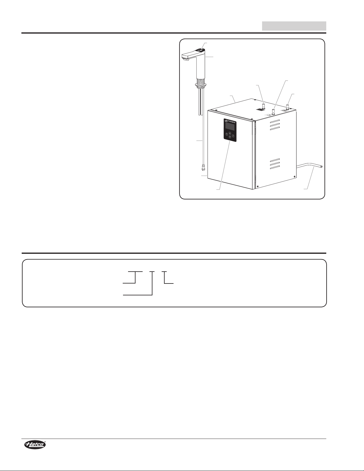
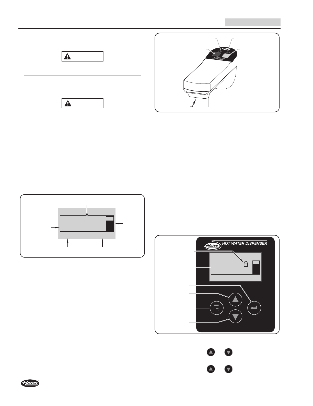
Hatco FLOWMAX®Hot Water Dispensers are designed to
provide pre-set quantities of instant hot or cold water for drink
and food preparation. A 5 liter (1.3 gallon) stainless steel tank
connected to the on-site water supply provides continuous hot
water. The setpoint temperature can be adjusted from 65–95°C
(150–200°F), with the factory default setting at 95°C (200°F).
Hatco Hot Water Dispensers are products of extensive research
and field testing. The materials used were selected for maximum
durability, attractive appearance, and optimum performance.
Every unit is inspected and tested thoroughly prior to shipment.
This manual provides the installation, safety, and operating
instructions for Hatco Hot Water Dispensers. Hatco recommends
all installation, operating, and safety instructions appearing in
this manual be read prior to installation or operation of a unit.
Safety information that appears in this manual is identified by
the following signal word panels:
WARNING
WARNING indicates a hazardous situation which, if not
avoided, could result in death or serious injury.
CAUTION
CAUTION indicates a hazardous situation which, if not
avoided, could result in minor or moderate injury.
NOTICE
NOTICE is used to address practices not related to
personal injury.
Important Owner Information.............................................. 2
Introduction...........................................................................2
Important Safety Information ..............................................3
Model Description ................................................................4
Model Designation ...............................................................4
Specifications .......................................................................5
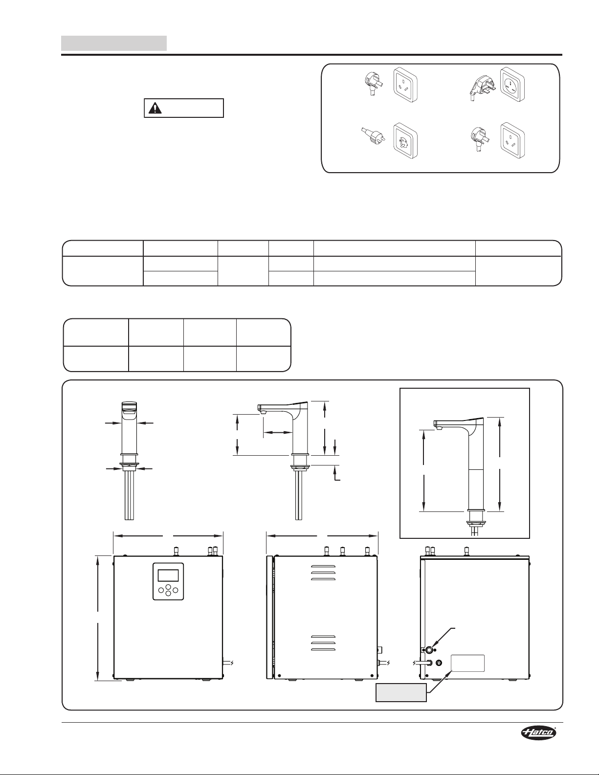
Plug Configurations .............................................................5
Electrical Rating Chart.........................................................5
Dimensions..........................................................................5
Countertop Cutout Dimensions ...........................................6
Installation.............................................................................6
General................................................................................ 6
Preparing for Installation .....................................................7
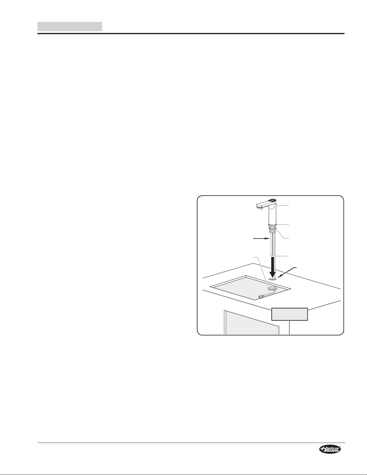
Installing the Faucet Assembly............................................7
Installing the Faucet with Font Assembly............................8
Installing and Connecting the Tank Unit..............................8
Testing the Connections ......................................................9
Operation.............................................................................10
General.............................................................................. 10
Locking/Unlocking the Control Panel ................................ 10
Changing the Setpoint Temperature.................................. 11
Adjusting/Changing the Dispense Mode ........................... 11
Using the Work Time Set Function.................................... 11
Changing Operating Mode ................................................12
Setting the Clock ...............................................................12
Resetting the Filter Life Counter .......................................12
Changing the Language ....................................................13
Using the Child Lock .........................................................13
Maintenance........................................................................ 14
General.............................................................................. 14
Daily Cleaning ...................................................................14
Changing the Water Filter .................................................14
Troubleshooting Guide ......................................................15
International Limited Warranty .........................................16
Service Information............................................................16
IMPORTANT OWNER INFORMATION
Record the model number, serial number, voltage, and
purchase date of the unit in the spaces below (specification
label located on the back of the tank unit). Please have this
information available when calling Hatco for service assistance.
Model No. _______________________________________
Serial No.________________________________________
Voltage__________________________________________
Date of Purchase__________________________________
Register your unit!
Completing online warranty registration will prevent delay in
obtaining warranty coverage. Access the Hatco website at
www.hatcocorp.com, select the Parts & Service pull-down
menu, and click on “Warranty Registration”.
Business 9:00 AM to 6:00 PM (Beijing Time)
Hours: Monday through Friday
Telephone: (0512) 6732-5091
E-mail: [email protected]
Additional information can be found by visiting our web site at
www.hatcocorp.com
INTRODUCTION
CONTENTS

Form No. FM5M_CN-1217 3
English IMPORTANT SAFETY INFORMATION
WARNING
ELECTRIC SHOCK HAZARD:
• Plug unit into a properly grounded electrical receptacle
of the correct voltage, size, and plug configuration. If
plug and receptacle do not match, contact a qualified
electrician to determine and install the proper voltage
and size electrical receptacle.
• Turn OFF power switch, unplug power cord, and
allow unit to cool before performing any cleaning,
adjustments, or maintenance.
• Unit is not weatherproof. Locate unit indoors.
• DO NOT submerge or saturate with water. Unit is not
waterproof. Do not operate if unit has been submerged
or saturated with water.
• Do not steam clean or use excessive water on unit.
• This unit is not “jet-proof” construction. Do not use
jet-clean spray to clean this unit.
• Discontinue use if power cord is frayed or worn.
• Do not attempt to repair or replace a damaged
power cord. The cord must be replaced by Hatco, an
Authorized Hatco Service Agent, or a person with
similar qualifications.
• This unit must be serviced by qualified personnel only.
Service by unqualified personnel may lead to electric
shock or burn.
• Use only Genuine Hatco Replacement Parts when
service is required. Failure to use Genuine Hatco
Replacement Parts will void all warranties and may
subject operators of the equipment to hazardous
electrical voltage, resulting in electrical shock or burn.
Genuine Hatco Replacement Parts are specified to
operate safely in the environments in which they are
used. Some aftermarket or generic replacement parts
do not have the characteristics that will allow them to
operate safely in Hatco equipment.
FIRE HAZARD:
• Allow a minimum clearance of 51 mm (2") along
sides of unit and 64 mm (2-1/2") along rear of unit.
If safe distances are not maintained, discoloration,
overheating, malfunction, or combustion could occur.
• Do not obstruct air ventilation openings on outer
housing of unit. Unit combustion or malfunction may
occur.
EXPLOSION HAZARD: Do not store or use gasoline or
other flammable vapors or liquids in the vicinity of this or
any other appliance.
This unit must be installed by qualified, trained installers.
Installation must conform to all local electrical and
plumbing codes. Check with local plumbing and electrical
inspectors for proper procedures and codes.
WARNING
Install tank unit in a horizontal position with the base
parallel to the floor. Improper installation could create an
unsafe condition.
Make sure all operators have been instructed on the safe
and proper use of the unit.
This unit is not intended for use by children or persons
with reduced physical, sensory, or mental capabilities.
Ensure proper supervision of children and keep them
away from the unit.
This unit has no “user-serviceable” parts. If service is
required on this unit, contact an Authorized Hatco Service
Agent or contact Hatco at (0512) 6732-5091.
CAUTION
BURN HAZARD:
• Some exterior surfaces on unit will get hot. Use caution
when touching these areas.
• Hot water in unit may cause scalding injury. Be aware
and use caution during operation to avoid injury.
• Steam escaping from vent on faucet assembly may
cause scalding injury. Do not place hands or other
body parts under faucet. Be aware and use caution at
all times around faucet assembly.
Locate faucet assembly at proper counter height in an
area that is convenient for use. Location should be level
to prevent filling containers from falling accidentally
and strong enough to support weight of container and
contents.
NOTICE
This unit is designed for use in environments where
ambient temperature is between 5°C (41°F) and 35°C (95°F).
Use non-abrasive cleaners and cloths only. Abrasive
cleaners and cloths could scratch finish of unit, marring its
appearance and making it susceptible to soil accumulation.
Clean unit daily to avoid malfunctions and maintain
sanitary operation.
This unit is intended for commercial use only—NOT for
household use.
Read the following important safety information before using this equipment to avoid serious
injury or death and to avoid damage to equipment or property.

4Form No. FM5M_CN-1217
English
Faucet Assembly
Tank Unit
Hot Water
Outlet Cold
Water
Outlet
Faucet Controls
Vent Outlet
Control
Panel
Access
Door
Data
Line
Power Cord
(plug not shown)
FM-5 Hot Water Dispenser
MODEL DESCRIPTION
Hatco FLOWMAX®Hot Water Dispensers are made up of
two assemblies—the faucet assembly and the tank unit. The
faucet assembly is installed in a countertop above a sink or
with the optional font assembly. It is equipped with controls and
indicator lights for dispensing hot and cold water. The tank unit
is installed in the cabinet underneath the faucet assembly. It is
equipped with a 5 liter (1.3 gallon) stainless steel tank, a water
filter, a Power I/O (on/off) switch, and electronic control panel,
and a 1.3 m (51ʺ) cord and plug set.
MODEL DESIGNATION
F M - 5 - T
FLOWMAX
Water Ta nk Capacity
(liters)
No Character = Touch-Style Faucet Keys
T = Tactile-Style Faucet Buttons

Form No. FM5M_CN-1217 5
English
Model
Width
(A)
Depth
(B)
Height
(C)
FM-5
FM-5-T
332 mm
(13-1/8″)
347 mm
(13-11/16″)
391 mm
(15-7/16″)
Model Voltage Watts Amps Plug Configuration Shipping Weight
FM-5
FM-5-T
220 VAC (CCC) 1800 W 8.2 A CPCS-CCC 18 kg (40 lbs.)
230 VAC (CE) 7.8 A BS-1363, CEE 7/7 Schuko, AS 3112
SPECIFICATIONS
Electrical Rating Chart
Plug Configurations
Units are supplied from the factory with an electrical cord and
plug installed. Plugs are supplied according to the application.
WARNING
ELECTRIC SHOCK HAZARD: Plug unit into a properly
grounded electrical receptacle of the correct voltage,
size, and plug configuration. If plug and receptacle do not
match, contact a qualified electrician to determine and
install the proper voltage and size electrical receptacle.
NOTE: Receptacle not supplied by Hatco.
CPCS-CCC
CEE 7/7 Schuko AS 3112
BS-1363
Plug Configurations
NOTE: The specification label is located on the back of the
tank unit. See label for serial number and verification
of unit electrical information.
Dimensions
C
Front View Side View Rear View
166 mm
92
mm
130 mm
255 mm
G 1/2" BSPP
Water Inlet
Fitting
Max. 30 mm
Counter
Thickness
A B
Ø = 46 mm
Ø = 40 mm 296 mm
Faucet Assembly
with Extension
Specification
Label

6Form No. FM5M_CN-1217
English
SPECIFICATIONS
Countertop Cutout Dimensions
Ø = 42 mm
Faucet Cutout
Faucet Assembly Only Faucet w/Optional Font Assembly
Ø = 42 mm
Faucet Cutout
Ø = 110 mm
Font Cutout
Ø = 7 mm
Cutout for Font Stud
115 mm
60 mm
INSTALLATION
General
FM-5 Hot Water Dispensers are shipped from the factory
completely assembled and ready for use. Use the following
information and procedures to prepare installation site and
install the unit.
WARNING
ELECTRIC SHOCK HAZARD:
• Plug unit into a properly grounded electrical receptacle
of the correct voltage, size, and plug configuration. If
plug and receptacle do not match, contact a qualified
electrician to determine and install the proper voltage
and size electrical receptacle.
• Unit is not weatherproof. Locate unit indoors.
FIRE HAZARD:
• Allow a minimum clearance of 51 mm (2″) along
sides of unit and 64 mm (2-1/2″) along rear of unit.
If safe distances are not maintained, discoloration,
overheating, malfunction, or combustion could occur.
• Do not obstruct air ventilation openings on outer
housing of unit. Unit combustion or malfunction may
occur.
This unit must be installed by qualified, trained installers.
Installation must conform to all local electrical and
plumbing codes. Check with local plumbing and electrical
inspectors for proper procedures and codes.
CAUTION
Locate faucet assembly at proper counter height in an
area that is convenient for use. Location should be level
to prevent filling containers from falling accidentally and
strong enough to support weight of container and contents.
NOTICE
This unit is designed for use in environments where
ambient temperature is between 5°C (41°F) and 35°C (95°F).
1. Remove the unit from the box.
2. Remove tape, protective packaging, and literature from all
surfaces of the unit.
NOTE: To prevent delay in obtaining warranty coverage,
complete online warranty registration. See the
IMPORTANT OWNER INFORMATION section for
details.

Form No. FM5M_CN-1217 7
English INSTALLATION
Installing the Faucet Assembly
Use the following procedure to install the faucet assembly.
NOTE: Make sure the installation of the faucet assembly will
allow the faucet to drain into a sink.
1. Using a hole saw, cut the appropriate opening in the
countertop for the faucet assembly. Refer to “Countertop
Cutout Dimensions” in the SPECIFICATIONS section.
2. Remove the mounting nut from the threaded pipe on the
bottom of the faucet assembly. Leave the decorative trim
ring on the faucet assembly.
3. Pass the faucet assembly with the data line, two water
pipes, and vent pipe through the counter top cutout from
above. Make sure the o-ring remains in position below the
trim ring on the faucet assembly.
4. Pass the data line, two water pipes, and vent pipe through
the mounting nut and thread the mounting nut onto the
threaded pipe underneath the countertop. Do not tighten
completely.
5. Make sure the faucet assembly is positioned properly to
drain into a sink, then tighten the mounting nut securely.
NOTE: Do not turn or twist the faucet assembly after final
installation.
Water and Vent Pipes
Mounting Nut
Countertop
Cutout
Faucet Assembly
O-Ring
Trim Ring
Data Line
Sink removed
for clarity.
Installing the Faucet Assembly
Preparing for Installation
Identify and prepare an appropriate installation site for the Hot
Water Dispenser. Refer to the following list of requirements.
1. Make sure the faucet assembly will be installed where it
can drain into a sink. If the optional font assembly will be
installed, a G 3/4" BSPP drain connection will be required
(no sink required).
2. Make sure the cabinet space where the tank unit will be
installed meets the following requirements:
• The tank unit must be installed be within 914 mm
(36ʺ) of the water and vent pipes at the bottom of the
faucet assembly. The water and vent tubes included
for connection between the tank unit and the faucet
assembly cannot be lengthened.
• The interior dimensions must provide enough space
with clearances for installation of the tank unit. Refer
to “Dimensions” in the SPECIFICATIONS section
of this manual. The tank unit requires an additional
64 mm (2-1/2") beyond the rear of the unit for connections
and 51 mm (2") along each side for ventilation.
• The cabinet floor must support the weight of the unit
when filled with water. Make structural modifications or
add bracing underneath the cabinet floor, if necessary.
• The cabinet must allow easy access to the front of the
tank unit with space to open the front door of the tank
unit.
3. Make sure a cold water supply line with a shut-off valve is
available inside the cabinet. The water supply line must
have a working pressure between 70 kPa (10 psi) and
700 kPa (102 psi). Install a pressure reducing valve, if
necessary.
NOTE: Hatco recommends the installation of a water pre-filter
on the cold water supply line before the Hot Water
Dispenser.
4. Make sure a grounded electrical receptacle of the correct
voltage, size, and plug configuration is within 1147 mm
(45ʺ) of the mounting location for the tank unit. See the
SPECIFICATIONS section for details.

8Form No. FM5M_CN-1217
English
INSTALLATION
Installing the Faucet with Font Assembly
Use the following procedure to install the faucet with font
assembly.
1. Using a hole saw, cut the appropriate openings in
the countertop for the faucet assembly and the font
assembly. Refer to “Countertop Cutout Dimensions” in the
SPECIFICATIONS section.
2. Apply a food-safe silicone sealant around the bottom edge
of the font assembly.
3. Place the font assembly into the cutouts. Make sure to
align the font stud with the font cutout and the faucet hole
with the faucet assembly cutout.
4. Place the stud washer followed by the stud nut onto the
font stud, and tighten against the bottom of the cutout.
5. Remove the mounting nut from the threaded pipe on the
bottom of the faucet assembly. Leave the decorative trim
ring and o-ring on the faucet assembly.
6. Pass the faucet assembly with the data line, two water
pipes, and vent pipe through the faucet hole in the font
assembly and through the countertop cutout from above.
Make sure the o-ring remains in position below the trim
ring on the faucet assembly and above the font assembly.
7. Pass the data line, two water pipes, and vent pipe through
the mounting nut and thread the mounting nut onto the
threaded pipe underneath the countertop. Do not tighten
completely.
8. Make sure the faucet assembly is positioned properly above
the font assembly, then tighten the mounting nut securely.
NOTE: Do not turn or twist the faucet assembly after final
installation.
9. Connect the G 3/4″ BSPP drain connection on the bottom
of the font assembly to the onsite drain system or use the
included drain tube components.
Drain
Tube
Countertop
Cutouts
Faucet Assembly
w/Extension
O-Ring
Trim Ring
Font Assembly
Font Stud
Stud
Washer
Stud
Nut
Mounting
Nut
Data Line
Installing the Faucet with Font Assembly
NOTE: Faucet with Font Assembly shown with extension piece.
Installing and Connecting the Tank Unit
Use the following procedure to install the tank unit in the
cabinet underneath the faucet assembly as well as to make
the connections to the faucet assembly.
NOTE: Do not place the tank unit in the cabinet until the
rear connections are complete. There may be limited
working space behind the tank unit once it is installed.
NOTE: Flush the cold water supply line thoroughly before
connecting to the water inlet fitting on the tank unit. This
will prevent sediment from entering the tank unit.
1. Connect a cold water supply line to the G 1/2ʺ BSPP water
inlet fitting on the back of the tank unit. Refer to “Preparing
for Installation” earlier in this section for water supply line
specifications.
2. Connect the data line from the faucet assembly to the data
port on the back of the tank unit. Tighten securely.
Faucet
Assembly
Tank Unit
Water Inlet
Fitting
Data
Port
Data
Line
Rear View of Tank Unit
3. Lift the tank unit into the cabinet.
• Be aware of the connected cold water supply line and
data line while placing the tank unit.
• Make sure there are minimum clearances of at least
51 mm (2ʺ) along the sides of the unit and 64 mm
(2-1/2ʺ) along the rear of the unit.
• Make sure there are no obstructions in front of the air
ventilation openings on each side of the unit.

Form No. FM5M_CN-1217 9
English INSTALLATION
Faucet assembly
installed.
Tank Unit
Air Vents
Sink removed
for clarity.
Installing the Tank Unit
4. Route and secure the data line so that it is not is vulnerable
to water exposure and does not rest on the floor of the
cabinet.
5. Connect the water tubes and vent tube between the faucet
assembly and the tank unit using the hose clamps provided.
Measure and trim each hose so that they run as straight as
possible without dips or kinks.
NOTE: The HOT water tube and COLD water tube are labeled.
The vent tube is a smaller diameter than the water
tubes.
a. Using hose clamps on each end, connect the hot water
pipe on the faucet assembly to the HOT OUTLET pipe
on top of the tank unit with the HOT water tube.
b. Using hose clamps on each end, connect the cold water
pipe on the faucet assembly to the COLD OUTLET pipe
on top of the tank unit with the COLD water tube.
c. Using hose clamps on each end, connect the vent pipe
on the faucet assembly to the VENT OUTLET pipe on
top of the tank unit with the vent tube.
Connect HOT
tube here.
Connect COLD
tube here.
Connect vent
tube here.
A
ccess
Door
Top View of Tank Unit
6. Open the access door on the tank unit and make sure the
water filter is installed and secure. To install:
a. Insert the filter up into the filter head.
b. Turn the filter counterclockwise until it seats up and
tightens into the filter head.
7. Plug the tank unit into a properly grounded electrical
receptacle of the correct voltage, size, and plug
configuration. See the SPECIFICATIONS section for
details.
Testing the Connections
Use the following procedure to test the installation of the Hot
Water Dispenser and make sure there are no leaks.
CAUTION
BURN HAZARD:
• Some exterior surfaces on unit will get hot. Use caution
when touching these areas.
• Hot water in unit may cause scalding injury. Be aware
and use caution during operation to avoid injury.
• Steam escaping from vent on faucet assembly may
cause scalding injury. Do not place hands or other
body parts under faucet. Be aware and use caution at
all times around faucet assembly.
1. Open the water supply line shut-off valve. Make sure no
water leaks at the water inlet fitting. Correct, if necessary.
2. Open the access door on the tank unit and move the Power
I/O (on/off) switch to the I (on) position.
• The control panel display will energize and show the
Main screen after it is finished starting up.
The water tank inside the tank unit will begin to fill and
heat. The tank fills in steps in order to reach setpoint
temperature quickly. The three-step tank fill level graphic
on the Main screen indicates the water level in the tank.
• The green “power” indicator on the faucet assembly will
illuminate. The red “temperature” indicator will flash until
water in the water tank reaches setpoint temperature,
when it will remain on steady.
3. Touch the blue Cold key on the faucet assembly to dispense
cold water. Repeat several times.
4. Touch the red Hot key on the faucet assembly to dispense
hot water. Repeat several times.
NOTE: The unit will continue to dispense hot water when water
in the tank is below setpoint temperature and the red
“temperature” indicator is flashing.
5. Check all water tube connections at the faucet assembly
and on top of the tank unit for leaks. Correct if necessary.
6. Check the water filter connection inside the tank unit for
leaks. Correct, if necessary.
7. Open the access door on the tank unit and move the Power
I/O (on/off) switch to the O (off) position.

10 Form No. FM5M_CN-1217
English
OPERATION
Hot Key
Temperature
Indicator
Nozzle
Power
Indicator
Cold Key
Faucet Assembly Controls
NOTE: The Hot and Cold keys on the faucet assembly can
be set to dispense after a single touch (One Touch) or
during a touch and hold (Hold Touch). The dispense
time for One Touch mode is adjustable. The dispense
time for Hold Touch mode is determined by how long
the key is held, up to 15 seconds. Refer to “Adjusting/
Changing the Dispense Mode” in this section for details.
5. Continue to use the Hot Water Dispenser as necessary.
Water will continue to enter the tank and be heated
during operation to maintain a steady supply of setpoint
temperature water.
Shutdown
1. Open the access door on the tank unit and move the
Power I/O (on/off) switch to the O (off) position.
2. Perform the “Daily Cleaning” procedure in the
MAINTENANCE section of this manual.
Locking/Unlocking the Control Panel
Use the following procedure to lock or unlock the keys on the
control panel.
Friday 10:30
SET
95°C °C
95
9848L NORMAL
Display
Up Arrow
Key
Menu Key
Down Arrow
Key
Enter Key
Icon indicates
control panel
keys are locked.
FM-5 Control Panel
1. To lock the control panel:
• Press and hold the and keys for three seconds.
2. To unlock the control panel:
• Press and hold the and keys for three seconds.
General
Use the following procedures to operate the FM-5 Hot Water
Dispenser.
WARNING
Read all safety messages in the Important Safety
Information section before operating this equipment.
This unit is not intended for use by children or persons
with reduced physical, sensory, or mental capabilities.
Ensure proper supervision of children and keep them away
from the unit.
CAUTION
BURN HAZARD:
• Some exterior surfaces on unit will get hot. Use caution
when touching these areas.
• Hot water in unit may cause scalding injury. Be aware
and use caution during operation to avoid injury.
• Steam escaping from vent on faucet assembly may
cause scalding injury. Do not place hands or other
body parts under faucet. Be aware and use caution at
all times around faucet assembly.
Startup
1. Open the access door on the tank unit and move the
Power I/O (on/off) switch to the I (on) position.
• The control panel display will energize and show the
Main screen after it is finished starting up.
Friday 10:30
SET
95°C °C
95
9848L NORMAL
Setpoint
Temperature
Tank Fill
Level
Operating
Mode
Current Water
Temperature
Filter Life
Remaining (liters)
Main Screen
• The water tank inside the tank unit will begin to fill and
heat. The tank fills in steps in order to reach setpoint
temperature quickly. The three-step tank fill level graphic
on the Main screen indicates the water level in the tank.
• The green “power” indicator on the faucet assembly will
illuminate.
• The red “temperature” indicator will flash until water in
the water tank reaches setpoint temperature. When the
water reaches setpoint temperature, the indicator will
remain on steady.
2. Place the desired container underneath the nozzle on the
faucet assembly.
3. Touch the desired key on the faucet assembly to dispense
water.
• Touch the red Hot key to dispense hot water. Hot water
will dispense for a pre-set number of seconds.
• Touch the blue Cold key to dispense room temperature
water. Room temperature water will dispense for a pre-
set number of seconds.

Form No. FM5M_CN-1217 11
English OPERATION
Changing Setpoint Temperature
Use the following procedure to change the setpoint temperature
for the hot water dispenser. The setpoint temperature can be
adjusted from 65–95°C (150–200°F)
1. From the Main screen, press the key. The Function
Set screen will appear:
2. Press the key to scroll down and highlight “2. Temp Set”.
3. Press the key. The Temp Set screen will appear.
• Press the key to increase setpoint value.
• Press the key to decrease setpoint value.
4. Press the key to save the setting and return to the
Function Set Screen.
5. Press the key to return to the Main Screen.
Adjusting/Changing the Dispense Mode
There are two dispense modes: One Touch and Hold Touch.
One Touch allows the operator to touch the Hot or Cold key
only once to dispense water for a preset number of seconds—
between five seconds and 15 seconds, in one second
increments. Hold Touch requires the operator to touch and hold
the Hot or Cold key to dispense water for the desired amount of
time, up to 15 seconds.
Use the following procedure to change or adjust the dispense
mode of the Hot Water Dispenser.
1. From the Main screen, press the key. The Function
Set screen will appear:
2. Press the key to scroll down and highlight “4. Dispense
Set”.
3. Press the key. The Dispense Set screen will appear.
• Press the or key to highlight the desired
dispense mode.
• If “1. One Touch” is selected, go to step #4.
• If “2. Hold Touch” is selected, go to step #5.
4. Press the key. The corresponding Dispense Time
screen will appear.
• Press the or key to adjust the dispense time.
5. Press the key to save the setting and return to the
Dispense Set screen.
6. Press the key twice to return to the Main Screen.
Using the Work Time Set Function
The “Work Time Set” function is used in Power Save mode and
allows the user to set a schedule for the operation of the Hot
Water Dispenser. Each day of the week can be programmed
with specific hours of operation. During non-working time, the
Power I/O (on/off) switch is left in the I (on) position, and the unit
goes into Power Save mode to save energy. After programming
the Work Time, the unit must be put into Power Save mode
using the “Changing Operating Mode” procedure in this section.
Use the following procedure to program the hours of operation
for the Work Time Set function.
1. From the Main screen, press the key. The Function
Set screen will appear:
2. Press the key to scroll down and highlight “3. Work Time
Set”.
3. Press the key. The Work Time Set screen will appear.
• Press the or key to change the highlighted
value. Changeable values include the hour and minute
for both the start time and end time of each day of the
week.
• Press the key to save the current value and move to
the next value.
NOTE: The Work Time Set screen will scroll automatically to
show the remaining days of the week after entering the
end time on Wednesday and pressing the key.
• After changing the last value, press the key to return
to the Function Set screen
4. Press the key to return to the Main Screen.

12 Form No. FM5M_CN-1217
English
OPERATION
Changing Operating Mode
Use the following procedure to change the operating mode of
the Hot Water Dispenser between “Normal” and “Power Save.”
Normal mode is the default mode for the Hot Water Dispenser.
Power Save mode is used with the “Work Time Set” function
and reduces the setpoint temperature to 65°C (149°F) during
non-working times to save energy (see the “Setting the Work
Time” procedure in this section).
1. From the Main screen, press the key. The Function
Set screen will appear. The function “1. Mode Set” will be
highlighted.
2. Press the key. The Mode Set screen will appear.
• Press the or key to highlight the desired
operating mode.
3. Press the key to save the setting and return to the
Function Set Screen.
4. Press the key to return to the Main Screen.
Setting the Clock
Use the following procedure to set the current time and day on
the display clock.
1. From the Main screen, press the key. The Function
Set screen will appear:
2. Press the key to scroll down and highlight “6. Clock Set”.
3. Press the key. The Clock Set screen will appear.
• Press the or key to change the highlighted
value. Changeable values include hour, minute, and day.
• Press the key to save the current value and move to
the next value.
• After changing the last value, press the key to return
to the Clock Set screen
4. Press the key twice to return to the Main Screen.
Resetting the Filter Life Counter
Use the following procedure to reset the filter life counter after
installing a new filter.
NOTE: The filter life counter is for reference only. Local water
pressure and frequency of use will affect the life span of
the filter.
1. From the Main screen, press the key. The Function
Set screen will appear:
2. Press the key to scroll down and highlight “5. Filter Set”.
3. Press the key. The Filter Set screen will appear.
• Press the key to highlight “2. Reset Filter”.
4. Press the key. The Filter Replaced screen will appear.
• Press the or key to highlight “YES”.
5. Press the key to reset the filter life counter and return
to the Filter Set screen.
6. Press the key twice to return to the Main Screen.

Form No. FM5M_CN-1217 13
English
Changing the Language
Use the following procedure to change the language of the Hot
Water Dispenser between English and Chinese.
1. From the Main screen, press the key. The Function
Set screen will appear:
2. Press the key to scroll down and highlight “7. Language
Set”.
3. Press the key. The Language Set screen will appear.
• Press the or key to highlight the desired
language.
4. Press the key to save the setting and return to the
Function Set Screen.
5. Press the key to return to the Main Screen.
Using the Child Lock
Use the following procedure to enable/disable the child lock
function for the Hot key on the faucet assembly.
1. From the Main screen, press the key. The Function
Set screen will appear:
2. Press the key to scroll down and highlight “8. Child Lock
Set”.
3. Press the key. The Child Lock Set screen will appear.
• Press the or key to highlight "1. ON" or "2. OFF".
4. Press the key to save the setting and return to the
Function Set Screen.
5. Press the key to return to the Main Screen.
Operating the Dispenser with Child Lock Enabled
The Child Lock function only applies to the Hot key on the faucet
assembly. Use the following procedure to operate the Hot key
when the Child Lock function is enabled.
Icon indicates Child Lock
is enabled.
Friday 10:30
SET
95°C °C
95
9848L NORMAL
Main Screen with Child Lock Enabled
1. Touch and hold the Hot key for two seconds to unlock the
key.
2. Touch the Hot key within two seconds to dispense hot
water.
• If the Hot key is not used within two seconds, the key will
re-lock.
OPERATION

14 Form No. FM5M_CN-1217
English
General
FM-5 Hot Water Dispensers are designed for maximum durability
and performance, with minimum maintenance.
WARNING
ELECTRIC SHOCK HAZARD:
• Turn OFF power switch, unplug power cord, and
allow unit to cool before performing any cleaning,
adjustments, or maintenance.
• DO NOT submerge or saturate with water. Unit is not
waterproof. Do not operate if unit has been submerged
or saturated with water.
• Do not steam clean or use excessive water on unit.
• This unit is not “jet-proof” construction. Do not use jet-
clean spray to clean this unit.
• Do not attempt to repair or replace a damaged
power cord. The cord must be replaced by Hatco, an
Authorized Hatco Service Agent, or a person with
similar qualifications.
• This unit must be serviced by qualified personnel only.
Service by unqualified personnel may lead to electric
shock or burn.
• Use only Genuine Hatco Replacement Parts when
service is required. Failure to use Genuine Hatco
Replacement Parts will void all warranties and may
subject operators of the equipment to hazardous
electrical voltage, resulting in electrical shock or burn.
Genuine Hatco Replacement Parts are specified to
operate safely in the environments in which they are
used. Some aftermarket or generic replacement parts
do not have the characteristics that will allow them to
operate safely in Hatco equipment.
This unit has no “user-serviceable” parts. If service is
required on this unit, contact an Authorized Hatco Service
Agent or contact Hatco at (0512) 6732-5091.
Daily Cleaning
To preserve the finish of the faucet assembluy as well as
maintain the performance of the entire unit, it is recommended
that the unit be cleaned daily.
NOTICE
Use non-abrasive cleaners and cloths only. Abrasive
cleaners and cloths could scratch finish of unit, marring its
appearance and making it susceptible to soil accumulation.
1. Open the access door on the tank unit and move the
Power I/O (on/off) switch to the O (off) position. Allow the
unit to cool.
2. Wipe down the faucet assembly using a clean, damp non-
abrasive cloth.
• Rinse cloth in hot water and repeat as necessary.
3. Wipe dry the faucet assembly with a clean, dry non-
abrasive cloth.
4. Clean the font assembly, if installed.
• Remove the strainer and clean with hot water and mild
soap. Wipe dry the strainer.
• Wipe inside the font well using a clean, damp non-
abrasive cloth. Repeat as necessary.
• Wipe dry the font well and replace the strainer.
NOTE: The tank unit will not require daily cleaning. Check and
clean the tank unit and its surrounding area on a weekly
basis.
Replacing the Water Filter
Use the following procedure to replace the water filter inside
the tank unit.
1. Open the access door on the tank unit and move the
Power I/O (on/off) switch to the O (off) position. Allow the
unit to cool.
NOTE: Use caution and be prepared for a small amount of
water to spill during filter removal. Hold the filter straight
up and do not tilt during removal. Wipe up any spilled
water immediately.
2. Turn the filter clockwise to unlock and remove the filter
from the filter head. Discard the old filter.
3. Install the new filter.
a. Insert the new filter up into the filter head.
b. Turn the filter counterclockwise until it seats up and
tightens into the filter head.
4. Perform the “Resetting the Filter Life Counter” procedure
in the OPERATION section of this manual.
MAINTENANCE

Form No. FM5M_CN-1217 15
English
Symptom Probable Cause Corrective Action
“Power” indicator on faucet not
lit and control display not on.
Power I/O (on/off) switch in O (off) position. Move Power I/O (on/off) switch on tank unit to the I (on)
position.
Unit not plugged in or outlet not working. Plug in unit, have outlet repaired by a certified electrician, or
use a different outlet.
Circuit breaker tripped. Reset circuit breaker. If circuit breaker continues to trip,
contact Authorized Service Agent or Hatco for assistance.
Unit is malfunctioning. Contact Authorized Service Agent or Hatco for assistance.
Unit does not dispense water. Water level in tank is too low. Allow unit to fill and heat.
Water supply is shut off or not connected. Make sure water supply is connected properly and turned
on.
Internal tank unit failure. Contact Authorized Service Agent or Hatco for assistance.
Water flowing slowly. Filter is old. Replace the water filter.
Inlet valve is blocked. Remove water supply line and check/clean inlet valve.
Install water pre-filter on water supply line.
Water is not hot. Heating element not working. Contact Authorized Service Agent or Hatco for assistance.
Relay and/or control board defective. Contact Authorized Service Agent or Hatco for assistance.
TROUBLESHOOTING GUIDE
WARNING
This unit must be serviced by trained and qualified
personnel only. Service by unqualified personnel may lead
to electric shock or burn.
WARNING
ELECTRIC SHOCK HAZARD: Turn OFF power switch,
unplug power cord, and allow unit to cool before
performing any cleaning, adjustments, or maintenance.
Troubleshooting Questions?
If you continue to have problems resolving an issue, please
contact the nearest Authorized Hatco Service Agency or Hatco
for assistance. To locate the nearest Service Agency, log
onto the Hatco website at www.hatcocorp.com and click on
Find Service Agent, or contact the Hatco Parts and Service
Team at:
Telephone: (0512) 6732-5091
e-mail: [email protected]
Error Codes
There are five error codes that may show on the control display.
Contact an Authorized Service Agent or Hatco for assistance.
E1: Water Level Error
E2: Temp Sensor Error
E3: Water Overflow Error
E4: Water Not Filling—Water has not filled to Level-1 after 10
minutes of filling.
E5: Not Heating—Water temperature has not reached setpoint
temperature after 30 minutes of heating.

16 Form No. FM5M_CN-1217
English
INTERNATIONAL LIMITED WARRANTY
1. PRODUCT WARRANTY
Hatco warrants the products that it manufactures (the
“Products”) to be free from defects in materials and
workmanship, under normal use and service, for a period of
one (1) year from the date of purchase when installed and
maintained in accordance with Hatco’s written instructions
or 18 months from the date of shipment from Hatco. Buyer
must establish the Product’s purchase date by registering the
Product with Hatco or by other means satisfactory to Hatco in
its sole discretion.
Hatco warrants the following Product components to be free
from defects in materials and workmanship from the date of
purchase (subject to the foregoing conditions) for the period(s)
of time and on the conditions listed below:
a) Two (2) Year Parts Warranty:
Conveyor Toaster Elements (metal sheathed)
Drawer Warmer Elements (metal sheathed)
Drawer Warmer Drawer Rollers and Slides
Strip Heater Elements (metal sheathed)
Display Warmer Elements (metal sheathed air heating)
Holding Cabinet Elements (metal sheathed air heating)
Heated Well Elements — HW and HWB Series
(metal sheathed)
b) Five (5) Year Parts Warranty:
3CS and FR Tanks
c) Ten (10) Year Parts Warranty:
Electric Booster Heater Tanks
Gas Booster Heater Tanks
d) Ninety (90) Day Parts Warranty:
Replacement Parts
THE FOREGOING WARRANTIES ARE EXCLUSIVE AND
IN LIEU OF ANY OTHER WARRANTY, EXPRESSED OR
IMPLIED, INCLUDING BUT NOT LIMITED TO ANY IMPLIED
WARRANTY OF MERCHANTABILITY OR FITNESS FOR
A PARTICULAR PURPOSE OR PATENT OR OTHER
INTELLECTUAL PROPERTY RIGHT INFRINGEMENT. Without
limiting the generality of the foregoing, SUCH WARRANTIES
DO NOT COVER: Coated incandescent light bulbs, fluorescent
lights, heat lamp bulbs, coated halogen light bulbs, halogen
heat lamp bulbs, xenon light bulbs, LED light tubes, glass
components, and fuses; Product failure in booster tank, fin
tube heat exchanger, or other water heating equipment caused
by liming, sediment buildup, chemical attack, or freezing;
or Product misuse, tampering or misapplication, improper
installation, or application of improper voltage.
2. LIMITATION OF REMEDIES AND DAMAGES
Hatco’s liability and Buyer’s exclusive remedy hereunder will
be limited solely to replacement of part or Product using, at
Hatco’s option, new or refurbished parts or Product by Hatco
or a Hatco-authorized service agency with respect to any
claim made within the applicable warranty period referred to
above. Hatco reserves the right to accept or reject any such
claim in whole or in part. In the context of this Limited Warranty,
“refurbished” means a part or Product that has been returned
to its original specifications by Hatco or a Hatco-authorized
service agency. Hatco will not accept the return of any Product
without prior written approval from Hatco, and all such approved
returns shall be made at Buyer’s sole expense. HATCO WILL
NOT BE LIABLE, UNDER ANY CIRCUMSTANCES, FOR
CONSEQUENTIAL OR INCIDENTAL DAMAGES, INCLUDING
BUT NOT LIMITED TO LABOR COSTS OR LOST PROFITS
RESULTING FROM THE USE OF OR INABILITY TO USE
THE PRODUCTS OR FROM THE PRODUCTS BEING
INCORPORATED IN OR BECOMING A COMPONENT OF
ANY OTHER PRODUCT OR GOODS.
SERVICE INFORMATION
The warranty on this Hatco unit is for one year from date of
purchase or eighteen months from date of shipping from Hatco,
whichever occurs first.
If you experience a problem with this unit during the warranty
period, please do the following:
Contact Local Hatco Dealer
When contacting the Hatco dealer for service assistance,
please supply the dealer with the following information to
ensure prompt processing:
• Model of unit
• Serial number (located on the unit)
• Specific problem with the unit
• Date of purchase
• Name of business
• Shipping address
• Contact name and phone number
The Hatco dealer will do the following:
• Provide replacement part(s) as required
• Submit warranty claim to Hatco for processing
Non-Warranty Problems
If you experience a non-warranty problem that requires
assistance, please contact the nearest Authorized Hatco
Service Agency.
To locate the nearest Service Agency:
• call Hatco at (0512) 6732-5091

中文
表号:FM5M_CN-1217 17
目录
Hatco FLOWMAX®智能饮水机旨在即时提供预设水量的热
水或冷水,以用来饮用及烹制食物。 接上现场水源的 5 升
(1.3 加仑)不锈钢水箱可以提供源源不断的热水。 设定温度
可在 65–95°C (150–200°F) 之间调节,出厂默认设置为 95°C
(200°F)。
Hatco 智能饮水机是经过大量研究和实地测试考验的产品。 所
用材料经久耐用,外型美观,性能优异。 每件设备在发货前都
经过严格的检验和测试。
本手册包含 Hatco 智能饮水机的安装、安全和操作说明。 在
安装或操作设备之前,Hatco 建议您先阅读本手册中的所有安
装、操作和安全说明。
本手册中的安全信息采用以下标志表示:
“警告”表示有危险情况,如果不加以避免,则可能导致
人身伤亡。
“小心”表示有危险情况,如果不加以避免,则可能导致
轻度或中度人身伤害。
“注意”用于提示不会涉及人身伤害的操作。
使用者重要注意事项 .............................................................17
简介 ......................................................................................17
重要安全说明........................................................................18
型号说明 ...............................................................................19
型号命名 ...............................................................................19
规格 ......................................................................................20
插头型式 ............................................................................20
电气参数表.........................................................................20
尺寸 ...................................................................................20
台面板开孔尺寸 .................................................................21
安装 ......................................................................................21
总则 ...................................................................................21
安装准备 ............................................................................22
安装水龙头组件 .................................................................22
安装带有接水盘组件的水龙头............................................23
安装和连接水箱设备 ..........................................................23
测试连接 ............................................................................24
操作 ......................................................................................25
总则 ...................................................................................25
锁定/解锁控制面板 ............................................................25
更改设定温度 .....................................................................26
调整/更改供水模式 ............................................................26
使用工作时间设定功能.......................................................26
更改工作模式 .....................................................................27
设定时钟 ............................................................................27
重置过滤器可过滤量计数器 ...............................................27
更改语言 ............................................................................27
使用儿童锁.........................................................................28
维护 ......................................................................................29
总则 ...................................................................................29
日常清理 ............................................................................29
更换滤水器.........................................................................29
故障处理指南........................................................................30
全球有限质保........................................................................31
服务信息 ...............................................................................31
使用者重要注意事项
请在下列空白处记下本设备的型号、序列号、电压和购买日期
(规格标签位于本水箱设备背面)。 在致电 Hatco 寻求服务
帮助时,请提供上述信息。
型号 ____________________________________________
序列号 __________________________________________
电压 ____________________________________________
购买日期 ________________________________________
工作时间: 北京时间 上午 9:00 – 下午 6:00 周一至周五
电话: (0512) 6732-5091
E-mail: [email protected]
查询更多信息请访问我们的网站:www.hatcocorp.com
简介

中文
表号:FM5M_CN-1217
18
触电危险:
• 将设备插头妥善插入有接地的电气插座内,插入前请核对电
压、规格和插头型式是否正确。如果插头和插座不匹配,请
和有正式资格的电工联系,以确定并安装电压和规格正确的
电气插座。
• 在进行任何清洁、调整或维护之前,请先关闭电源开关,拔
下电源线,并使设备冷却。
• 设备不防水。 请将设备置于室内。
• 禁止将设备浸入水中。本设备不防水。 严禁使用被水浸过
的设备。
• 不得用蒸汽或使用过多的水清洁设备。
• 本设备不具备防喷淋结构。请勿使用喷淋头清洁本设备。
• 如果电源线磨损或者破损,请停止使用。
• 如果电源线出现磨损,不要试图自行维修或更换。电源线必
须由HATCO、HATCO授权服务机构或具备类似资质的人员
进行更换以免发生危害。
• 本设备必须由具备相应资质的人员进行维修。由布具备相应
资质的人员维修可能导致触电或起火。
• 维修时只能使用正品HATCO更换零部件。未使用正品
HATCO更换零部件会导致质保失效及造成设备操作人员受
到有害电压威胁,并引起触电或着火。正品HATCO更换零
部件可以保证使用环境下的安全生产,某些普通零部件不具
备相关特性,从而无法保证在HATCO设备的安全使用。
火灾危险:
• 请在设备两侧留出至少 51 mm (2") 的空间,并在设备后方
留出至少 64 mm (2-1/2") 的空间。 如果不保持安全距离,
可能会导致褪色、过热、故障或燃烧。
• 请勿堵塞设备外壳上的排气口。 设备可能会燃烧或出现故
障。
爆炸危险: 请勿在设备或其它电器周围储存或使用汽油类或其它
易燃气体和液体。
本设备只能由受过培训且具备相应资格的人员负责安装。 安装
时必须遵循所有的当地电气和管道规程。 有关相应的程序和规
程,请咨询当地的管道和电气审查员。
请将水箱设备安装在水平位置上,并使底座与地面平行。 安装
不当可能会引起危险情况。
确保所有操作人员受过安全正确使用设备的培训。
本设备未针对儿童和体质偏弱、过敏和精神失常人群使用做相
应设计。确保对儿童进行适当看管,使他们远离设备。
本设备不含“用户维修”零部件。如需维修,请联系HATCO授权
服务机构或HATCO服务部门,电话 (0512) 6732-5091。
烫伤危险:
• 本设备的某些外表面处温度较高,接触这些部位时请务必小
心。
• 设备中的热水可能会灼伤人体。 操作时请留意并小心使
用,以免受伤。
• 从水龙头组件的排气孔中排出的蒸汽可能会灼伤人体。 请
勿将手或其他身体部位置于水龙头下方。 在水龙头组件周
围进行操作时,请务必留意并小心使用。
请将水龙头组件置于便于使用的区域并使其处于适宜的台面高
度。 放置位置应保持水平,以防承装容器意外跌落;还应有足
够的强度,以承受容器及承装物的重量。
本设备旨在用于环境温度在 5°C (41°F) 和35°C (95°F) 之间的
环境中。
只允许使用没有摩擦性的清洁剂和布。 具有摩擦性的清洁剂
和布可能会刮伤设备的表面处理层,破坏其外观,并易使表面
积尘。
设备需要每天清洁,以免出现故障;另外,操作时请保持卫
生。
本设备仅适于商业用途 —非家用设备。
使用本设备前,请仔细阅读下列重要安全事项,以免造成严重的人身伤亡及设备或财产的损坏。
重要安全说明

中文
表号:FM5M_CN-1217 19
型号命名
F M - 5 - T
FLOWMAX ႇᏍ࠲!= ۂಝ༽ဂՙ
T = ۂࡥ༽ဂՙഀ
༽ძ๒˄໐˅
༽ဂᏠ
༽ძົֻ
༽ڵଁ
୩༽ڵଁ
༽ဂ૿፟ධ
ഠනڵଁ
૿፟ಅ֊
৹ᅃ
༮દღ
ݢኑღ˄نဂၝმ˅
FM-5 智能饮水机
型号说明
Hatco FLOWMAX® 智能饮水机由两个组件构成:水龙头组件
和水箱设备。 水龙头组件应装在位于水槽上方的台面板上,或
装配可选的接水盘组件。 它配备了用于热水和冷水供应的控制
器和指示灯。 水箱设备应装在位于水龙头组件下方的柜子中。
它配备了 5 升(1.3 加仑)的不锈钢水箱、滤水器、电源 I/O
(打开/关闭)开关、电子控制面板、1.3 m (51ʺ) 电线和插头。

中文
表号:FM5M_CN-1217
20
型号
宽度
(A)
深度
(B)
高度
(C)
FM-5
FM-5-T
332 mm
(13-1/8″)
347 mm
(13-11/16″)
391 mm
(15-7/16″)
型号 电压 功率 电流 插头型式 出厂重量
FM-5
FM-5-T
220 VAC (CCC) 1800 W 8.2 A CPCS-CCC 18 kg (40 磅)
230 VAC (CE) 7.8 A BS-1363, CEE 7/7 Schuko, AS 3112
规格
插头型式
设备出产时,随机配备电源线和插头。插头根据实际使用情况
配备。
触电危险:将设备插头妥善插入有接地的电气插座内,插入前
请核对电压、规格和插头型式是否正确。如果插头和插座不匹
配,请和有正式资格的电工联系,以确定并安装电压和规格正
确的电气插座。
注意:
HATCO
不
提供插座。
CPCS-CCC
CEE 7/7 Schuko AS 3112
BS-1363
Plug Configurations
注意:规格标签位于水箱设备的背面。
查看标签上的序列号和
设备电气参数信息。
电气参数表
尺寸
C
༄ဇ ف༄ဇ ༄ဇ
166 mm
92
mm
130 mm
255 mm
G ½" BSPP
༽ଁଁ
Ꮵܐྕಅޡၓ 30 mm
A B
Ø = 46 mm
Ø = 40 mm 296 mm
ܕ૰ᆖܿဂᏠ
ࣙࢆව
This manual suits for next models
2
Table of contents
Other Hatco Water Dispenser manuals
Popular Water Dispenser manuals by other brands

Water Right
Water Right Impression Plus Series Installation instructions & owner's manual

Culligan
Culligan Water Tower owner's guide

Greenway Home Products
Greenway Home Products GWD5500WBC Use & care guide

vitapur
vitapur VWD866W-4 Use & care guide

Kenmore
Kenmore 625.3484400 owner's manual

Classeq
Classeq WS-08 Technical data

gledhill
gledhill PulsaCoil PCS 120 Design, installation & servicing instructions

Halsey Taylor
Halsey Taylor OVL OVL-II ER-Q owner's manual

Field Controls
Field Controls 46300500 manual

H2O International
H2O International H2O 1000 Operation manual

vo-water
vo-water duomatik evoline installation guide

GEL
GEL DECAL BASIC Operation and maintenance manual