Hathor Energy HATHOR-16TM User manual

HATHOR
DAILY WEEKLY TIMER
WITH PHOTO SENSOR
HATHOR-16TM
1
info@hathorenergy.com
www.hathorenergy.com

2
HATHOR
DAILY WEEKLY TIMER WITH
PHOTO SENSOR
HATHOR-16TM
HATHOR-16TM
HATHOR-16TMDaily-Weekly Timer combines the following functions:
•Voltage relay
•Photo relay
•Real time relay
And is designed for:
•Load energizing/de-energizing in accordance with the user-set make/break
time
•De-energizing load in case of inadmissible voltage variations in the mains
with subsequent automatic re-energizing after the mains parameters
recovery
•Load energizing/de-energizing in accordance with the user-set illumination
intensity levels
The relay provides for the following modes of operation:
Weekly timer
•Voltage relay
•Photo relay
•Weekly timer with voltage control
•Photo relay with voltage control
The LEDs on the relay front panel indicate:
Presence of voltage in the mains
•Load status (ON/OFF)
•The relay operation mode
info@hathorenergy.com
www.hathorenergy.com

3
HATHOR
DAILY WEEKLY TIMER WITH
PHOTO SENSOR
HATHOR-16TM
The four-digit, seven-segment display depending on the operation mode
displays:
•Current time
•Actual value of mains voltage
•Illumination intensity
•Sequentially:Actual time and mains voltage
•Sequentially:Illumination intensity and actual mains voltage
The photosensitive diode which monitors the illumination intensity is
installed on the device front panel.An external photosensitive diode
connection is also possible.
The HATHOR-16TM relay output terminals can immediately switch wattage
load of up to 3.5 kW (16A).When it is necessary to switch greater wattage, a
magnetic starter should be utilized.
The device menu allows:
•Selecting the operation mode
•Choosing and editing the parameters set
•Clearing current parameter set
•Viewing the events list
•Creating an events list
•Setting the current time
•Setting the time of load energizing and de-energizing
•Setting up week day
•Setting the threshold of the minimum permitted voltage
•Setting the threshold of the maximum permitted voltage
info@hathorenergy.com
www.hathorenergy.com

4
HATHOR
DAILY WEEKLY TIMER WITH
PHOTO SENSOR
HATHOR-16TM
•Setting the time of load cutoff tripping based on the upper voltage
threshold
•Setting the time of load cutoff tripping based on the lower voltage
threshold
•Setting the time of load cutoff tripping after the mains parameters recovery
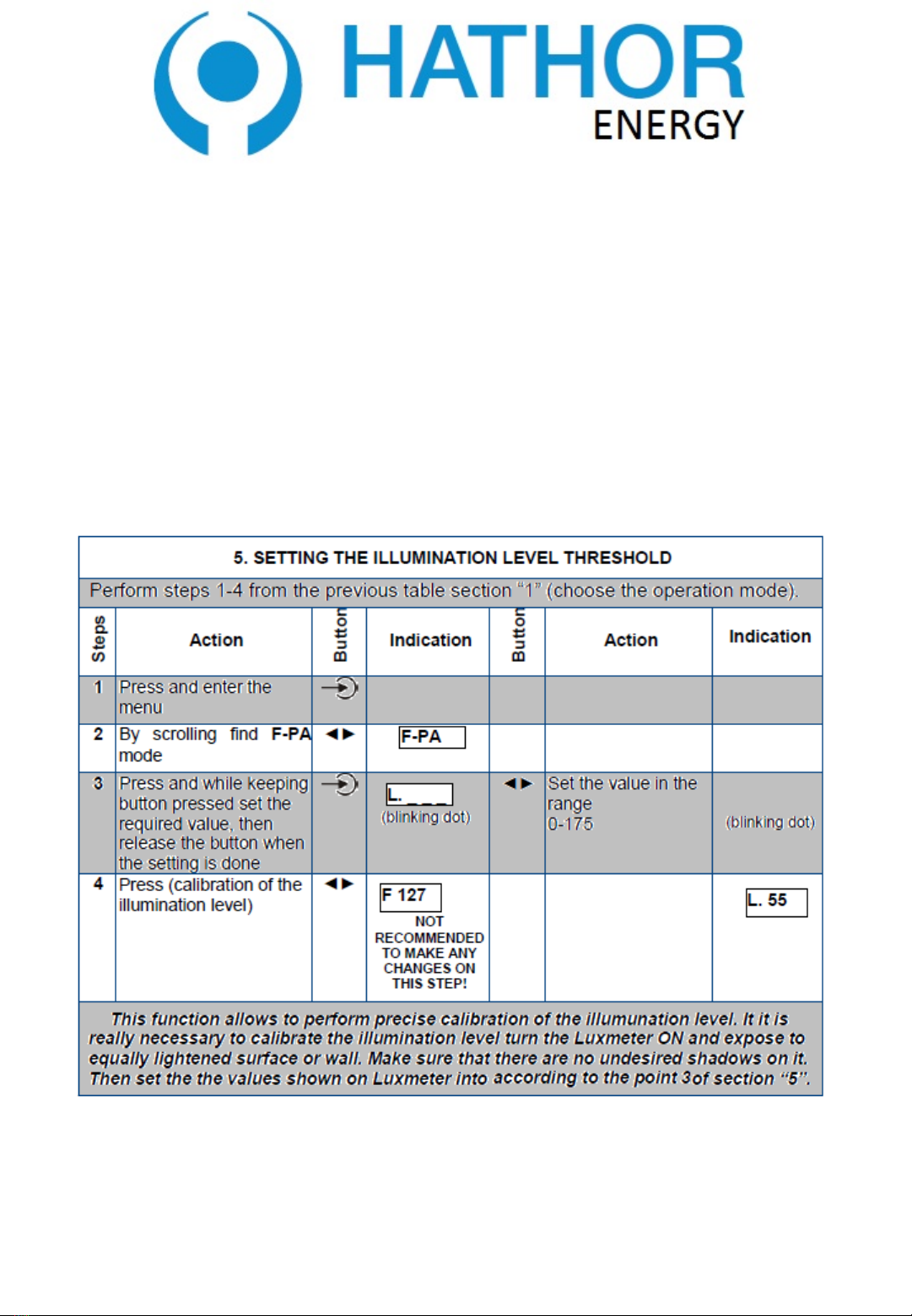
•Setting the illumination threshold
In case of mains voltage loss, the built-in battery allows storing the set
parameters within one month period.
info@hathorenergy.com
www.hathorenergy.com

5
HATHOR
DAILY WEEKLY TIMER WITH
PHOTO SENSOR
HATHOR-16TM SERVICE MANUAL
1APPLICATION
Multifunctional relay HATHOR-16TM (hereinafter HATHOR-16TM)performs
the following functions:
-Programmable real time switch (daily-weekly timer)
-MIN/MAX voltage relay
-Light-sensitive photo relay
-Voltage indicator
The HATHOR-16TM is designed for: - Turning ON/OFF the power load
(equipment) according to the time schedule preset by the user;-Turn OFF
home used or industrial single phase (240V / 50Hz) power load (equipment)
in case the unallowable voltage fluctuations are detected.When the voltage
returns back to normal parameters -the device will automatically turn ON
the power load (equipment) with the user defined time delay;-Turn ON/OFF
the power load according to the curtain illumination level that the user may
set
Relay works in 3basic operation modes (I-III) and 2mixed modes (IV-V):
I. Н–daily-weekly timer;
II. U – MIN/MAX voltage relay;
III. F – photo-relay;
IV.HU –daily-weekly timer with voltage control function;
V. FU –photo-relay with voltage control function.
Depending on the preset operation mode the LED display of the HATHOR-
16TMindicates the following information (please see article “6” on Figure1).
info@hathorenergy.com
www.hathorenergy.com

6
HATHOR
DAILY WEEKLY TIMER WITH
PHOTO SENSOR
HATHOR-16TM SERVICE MANUAL
I. Mode Н-current time in format :hours –blinking point –minutes
16 hours 45 minutes
II.Mode U - present voltage level correct to the nearest tenth
221.5 Volts
III.Mode F - letter F - space –illumination level
illumination level 35
IV.Mode HU -time and voltage values are shown one after another divided
by dashed line
V. Mode FU -illumination level and voltage level are shown one after
another divided by dashed line
The User may create 2different independent sets of parameters SP1, SP2
and may delete any of these sets if necessary.Thus the client may save in
the device memory 2different settings for curtain cases.
Output terminals of the HATHOR-16TM may commutate the power load up
to 3,5 kW (16A).If total power load connected to the HATHOR-16TM is more
than 3,5 kW (16A) then it will be necessary to commutate the required power
load with ause of appropriate contactor (magnetic starter).The HATHOR-
16TM should operate with the magnetic coil of contactor and thus the
required power load will be turned ON/OF.Please kindly note that the
contactor is not apart supplied along with the HATHOR-16TM.
info@hathorenergy.com
www.hathorenergy.com

7
HATHOR
DAILY WEEKLY TIMER WITH
PHOTO SENSOR
HATHOR-16TM SERVICE MANUAL
1–green LED indicates the “ON” state of relay;
2–green/red LED signal indicates the input voltage presence;
3–light sensor (photodiode);
4–menu control buttons:
–entry into menu, parameter input;
–save the parameter and menu exit;
–scrolling buttons;
5, 8 – wiring terminals;
6–seven-segment indicator (display);
7–green LEDs to indicate the operation mode of the relay;
9–strap of internal accumulator (set at the use of relay), during storage to
take off astrap.
FIGURE 1. Controls description and dimension diagrams
info@hathorenergy.com
www.hathorenergy.com

8
HATHOR
DAILY WEEKLY TIMER WITH
PHOTO SENSOR
HATHOR-16TM SERVICE MANUAL
2 TECHNICAL PARAMETERS
info@hathorenergy.com
www.hathorenergy.com

9
HATHOR
DAILY WEEKLY TIMER WITH
PHOTO SENSOR
HATHOR-16TM SERVICE MANUAL
3GENERAL DESCRIPTION
The mains power supply 240V50Hz should be connected to «(1-1) – (2-2)»
terminals of the HATHOR-16TM.For wiring convenience terminals 1-1 are
the one connection point and 2-2 terminals -another connection point.
Output contacts have changeover relay 3 – 4. In atime of exploitation of
relay astrap is set 5-6.This strap is connect the internal accumulator of
reserve clock motion.For warehousing of device it is recommended to take
off this strap that will substantially increase lifetime of accumulator.Power
load is being connected using terminals 3-4.
If the HATHOR-16TM detects the unallowable OVER/UNDER voltage, then it
will turn OFF the power load by opening the contacts 3-4 and in case of
using the contactor that will turn OFF the power for the magnetic coil of the
contactor and thus disconnect any required equipment.As soon as voltage
parameters restore and return back to normal values –HATHOR-16TM will
automatically turn ON the power load within the preset autoreclosing time
delay.Present status of the relay -ON/OFF states of the output contacts are
indicated by green LED light “ON” in the left upper corner of the front panel
(Figure 1; point – 1). Current operation mode of the HATHOR-16TM is
marked by green LEDs “F”, “U”, “H” on the front panel (Figure 1; point – 7).
All the adjustments and parameter settings could be subdivided into two
groups:BASIC and PARAMETER settings.
info@hathorenergy.com
www.hathorenergy.com

10
HATHOR
DAILY WEEKLY TIMER WITH
PHOTO SENSOR
HATHOR-16TM SERVICE MANUAL
BASIC SETTINGS:
-to set the operation mode (“F”, “U”, “H”) of the HATHOR-16TM;
-to set the operation mode and curtain user required set of
parameters (there are 2independent sets of parameters (programs) that the
user may keep in the device memory);
-to choose one of the available set of parameters (SP1or SP2);
-to clear (delete) current set of parameters.
PARAMETER SETTINGS:
-to view the events (parameters) preprogrammed in the HATHOR-
……….. 16TM;
-to enter the menu for adjustment of parameters (events);
-current time setting menu;
-time setting for turn ON;
-time setting for turn OFF;
-for the required day of the week;
-menu to set the voltage threshold values;
info@hathorenergy.com
www.hathorenergy.com
11
HATHOR
DAILY WEEKLY TIMER WITH
PHOTO SENSOR
HATHOR-16TM SERVICE MANUAL
-upper voltage threshold setting;
-lower voltage threshold setting;
-time delay to turn OFF when high voltage detected (if voltage is
more than upper voltage threshold value);
-time delay to turn OFF when low voltage is detected (if voltage is
less than lower voltage threshold value);
-time delay to turn OFF when high voltage is detected (if voltage is
more than upper voltage threshold value);
-illumination level threshold setting.
Important notes:
Quality of the mains voltage power supply doesn’t influence on the
preprogrammed operation schedule of the HATHOR-16TM.So after the
normalization of the voltage parameters power load will be turned ON again,
but according to the time schedule preset by the user.If mains voltage was
absent not more than 1month (device was disconnected for 30 days) all the
parameters and settings will be safely kept in the HATHOR-16TM memory.
Output contacts of the relay will be kept in acold initial state.For example
HATHOR-16TM was preprogrammed such away that every day of aweek it
turn ON the power load at 22:00 and then at 8:00 in the morning of next day
it turns the power load OFF.Let’s assume that at 22:30 on Monday mains
voltage disappeared and then recovered back only on Wednesday at 6:00 in
the morning.So when voltage disappeared contacts 3-4 opened.
info@hathorenergy.com
www.hathorenergy.com

12
HATHOR
DAILY WEEKLY TIMER WITH
PHOTO SENSOR
HATHOR-16TM SERVICE MANUAL
As soon as the power load restore and return back to normal values
HATHOR-16TM will turn ON the power load again but according to the
preprogrammed schedule of operation.So at 6:00 when the power return –
it will turn ON the power load and at 8:00 in the morning that will turn it OFF
according the schedule.
4FIRST STARTUP PROCEDURES AND OPERATION
ALGORHYTM
For preservation of working capacity of an inner clock when disappearance
of voltage, it is necessary to establish astrap 5-6 (Figure 1). Preliminary
start up procedures include the following steps:
•setting of the current time and the day of aweek;
•setting the schedule of events (exact time values and days of aweek when
the power load should be turned ON and turned OFF as per users
requirements);
•setting the voltage tripping thresholds for MIN/MAX allowed voltage values
•setting the delay times to turn ON for UPPER/LOWER voltage thresholds
•setting the autoreclosing time delay
•setting the level of illumination (if necessary)
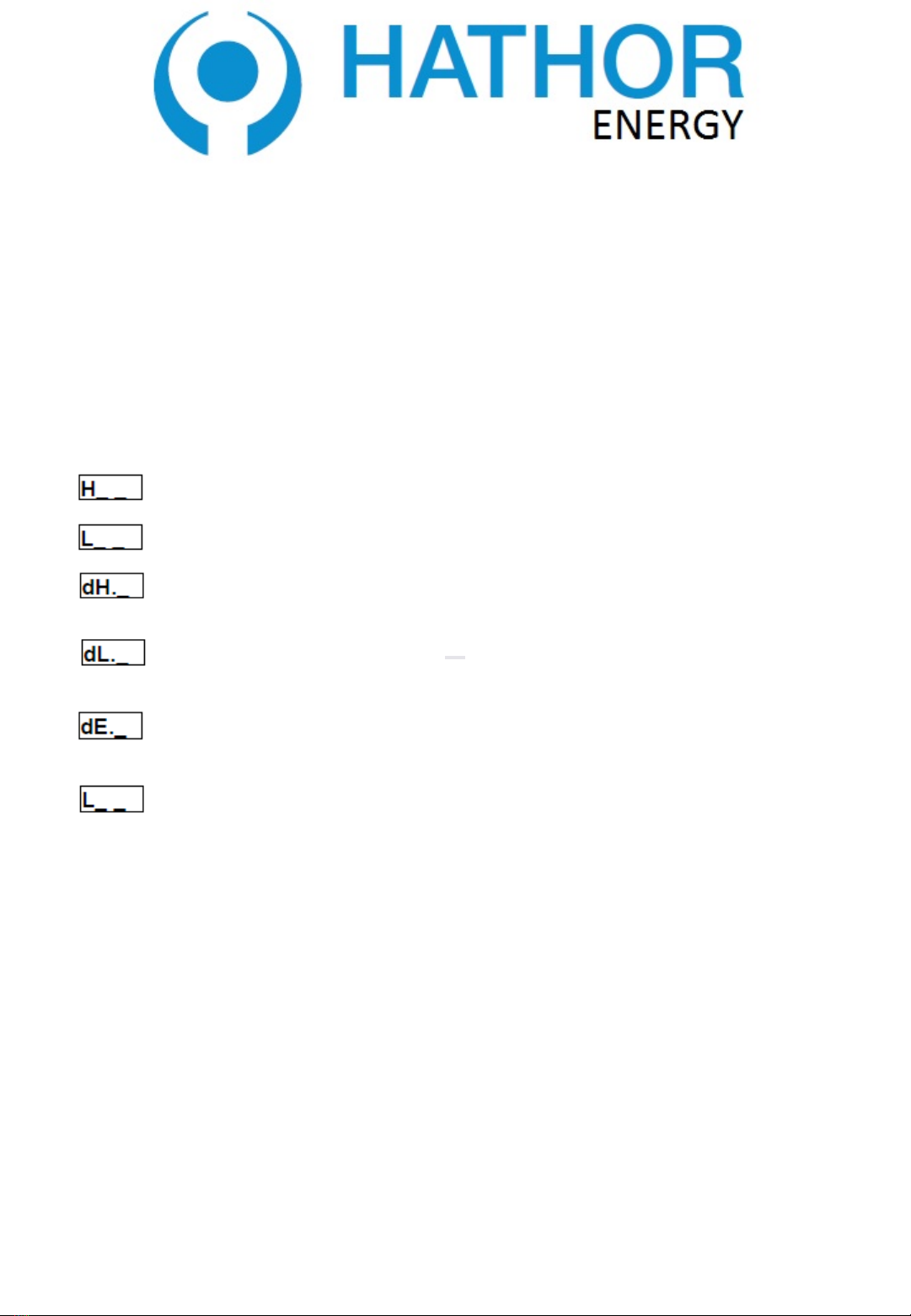
If in the menu some parameter or event is seen blank (“_”) then the event or
parameter in not set.When setting the time event schedule it’s possible to
adjust the following parameters:
-turn ON time; - turn OFF time; - current time
where: “01” – is number of event (ON/OFF);
info@hathorenergy.com
www.hathorenergy.com

13
HATHOR
DAILY WEEKLY TIMER WITH
PHOTO SENSOR
HATHOR-16TM SERVICE MANUAL
x – days of aweek, it’s possible to set 1-7 values (Monday – 1; Tuesday – 2;
Wednesday – 3; Thursday – 4; Friday – 5; Saturday – 6; Sunday – 7);
A – equal time-schedule for all days of aweek;
B – equal time-schedule for working days (Monday-Friday);
C – equal time-schedule events for weekend days (Saturday-Sunday);
To give the power supply to the HATHOR-16TM it’s necessary to connect
mains voltage wires to 1-1 and 2-2 input contact terminals.
ATTENTION! All connections of terminals should be performed strictly
according to safety regulations and in the absence of voltage in the mains.
So before wiring make sure that the wire terminals are not under voltage.
To every operation mode there is acurtain set of the items in menu shown
on display (please see Figure 1; point 6). To view all those items it’s
necessary to press button and then scroll the parameters by pressing
button.
info@hathorenergy.com
www.hathorenergy.com

14
HATHOR
DAILY WEEKLY TIMER WITH
PHOTO SENSOR
HATHOR-16TM SERVICE MANUAL
Kindly remember that maximal number of events in Hmode is 60 (30 Turn
ON events and 30 turn OFF events).Number of ON/OFF events is not
necessarily the same.
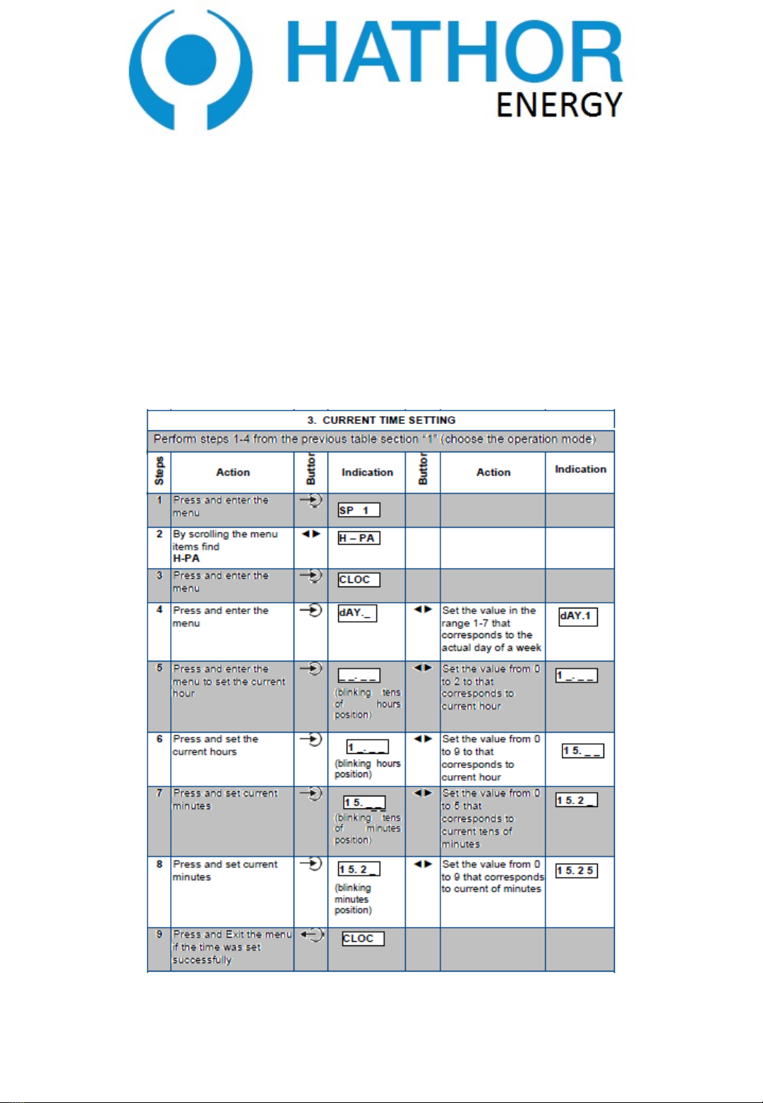
Notes:To set the time it’s necessary to input all digits including “0”. For
example 7:35 morning time should be set as 07:35.
After setting the schedule of events for HATHOR-16TM it’s necessary to
connect the power load to the output contacts of HATHOR-16TM.
ATTENTION! In order to prevent possible electric shock all the connections
of the power load should be performed according safety regulations and on
the de-energized HATHOR-16TM.
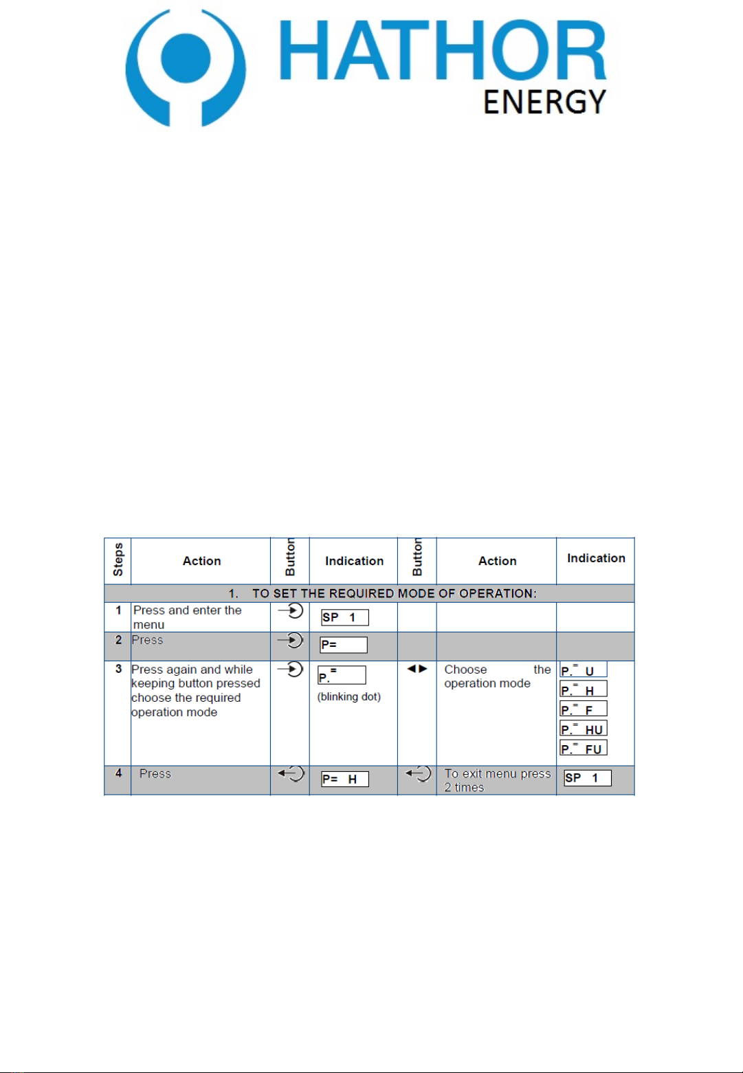
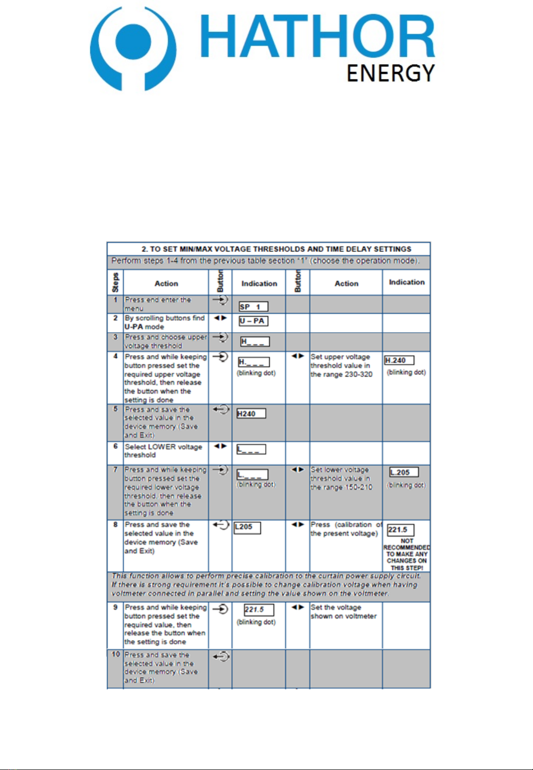
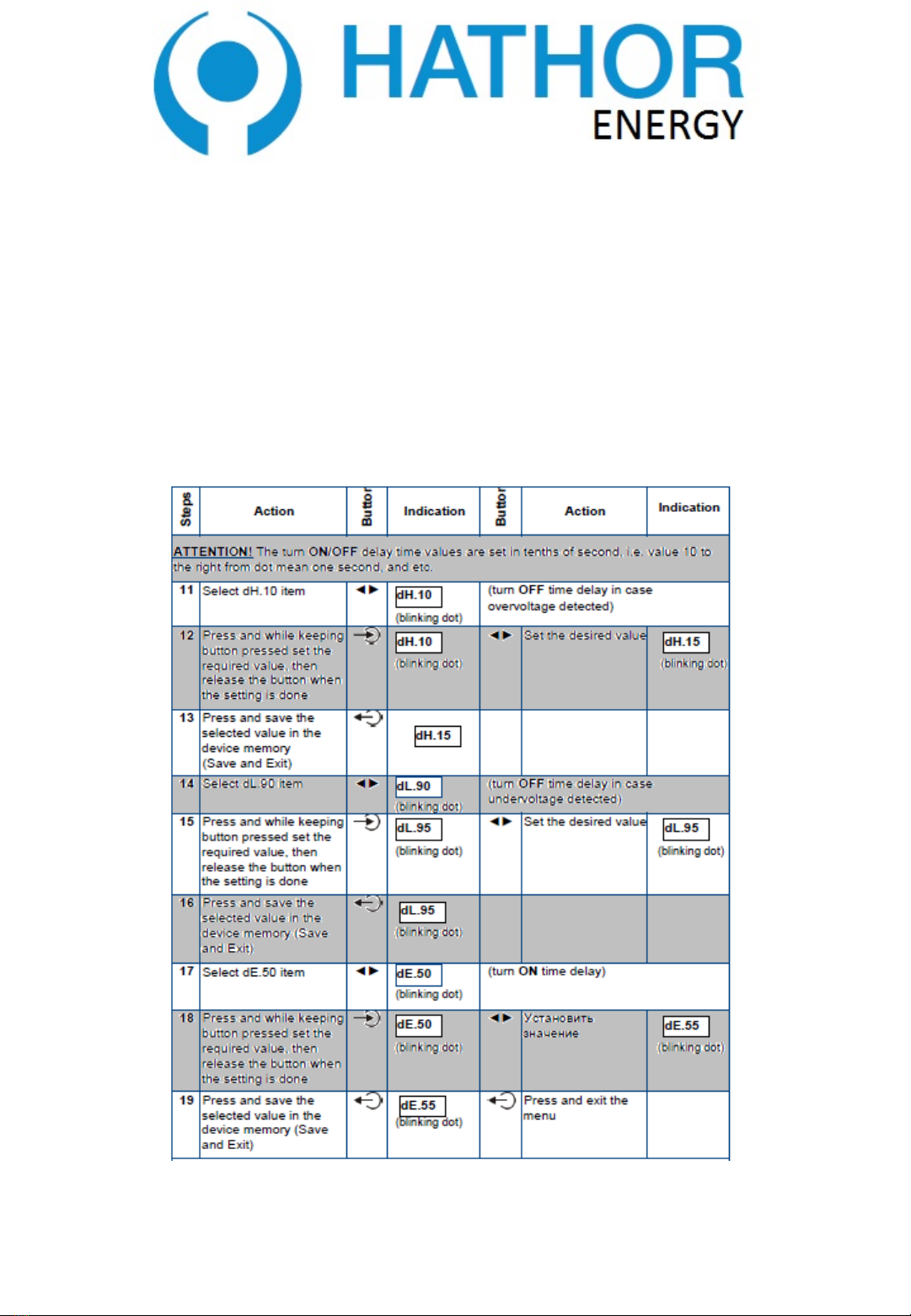
To preprogram the HATHOR-16TM according to the desired mode of
operation and input the required time schedule it’s necessary to follow the
steps shown in the table below:(in table example values of parameters are
shown and the User may change them as per requirements)
info@hathorenergy.com
www.hathorenergy.com
15
HATHOR
DAILY WEEKLY TIMER WITH
PHOTO SENSOR
HATHOR-16TM SERVICE MANUAL
info@hathorenergy.com
www.hathorenergy.com
16
HATHOR
DAILY WEEKLY TIMER WITH PHOTO
SENSOR
HATHOR-16TM SERVICE MANUAL
info@hathorenergy.com
www.hathorenergy.com
17
HATHOR
DAILY WEEKLY TIMER WITH
PHOTO SENSOR
HATHOR-16TM SERVICE MANUAL
info@hathorenergy.com
www.hathorenergy.com
18
HATHOR
DAILY WEEKLY TIMER WITH
PHOTO SENSOR
HATHOR-16TM SERVICE MANUAL
info@hathorenergy.com
www.hathorenergy.com

19
HATHOR
DAILY WEEKLY TIMER WITH
PHOTO SENSOR
HATHOR-16TM SERVICE MANUAL
info@hathorenergy.com
www.hathorenergy.com
20
HATHOR
DAILY WEEKLY TIMER WITH
PHOTO SENSOR
HATHOR-16TM SERVICE MANUAL
info@hathorenergy.com
www.hathorenergy.com
Table of contents


