EAPL ST-4M1 V2.0 User manual

CREATED ON: May 24, 2018
Instruction Manual
ST-4M1 V2.0
SEQUENTIAL TIMER WITH 4 HANNELS
EAPL
Introduction
On power application and continuou horting of S1 & S2 terminal ,
Timing equence of the 1 tchannel (CH1) i initiated by witching the
relay ON and ON-time tart . At the end of the ON-time relay goe
OFF and OFF-time tart . After completion of the OFF-time CH2 relay
come ON and ON-time tart followed by OFF-time. Thi equence
continue for re t of the channel . After the OFF-time of CH4, again
the CH1 relay come ON and thi cycle keep repeating till the power
i interrupted.
Box Accessories
One (1) ST-4M1 SEQUENTIAL TIMER WITH 4 CHANNELS
One (1) In truction manual.
Safety Precautions
Read and follow all the afety precaution and in truction before
in talling and working with the equipment.
• S1- S2 tart ignal hall be applied.
• Shorting of S1-S2 hall be potential free; applying power to the e
terminal will damage the timer permanently.
!
DANGER
HAZARD OF ELE TRI SHO K, EXPLOSION OR AR FLASH
• Apply appropriate per onal protective equipment(PPE) and follow afety
work practice
• Only qualified electrical worker hould in tall thi equipment. Such work
hould be performed only after reading thi entire et of in truction .
• If the equipment i not u ed in the manner pecified by the
manufacturer, the protection provided by the equipment may be
impaired.
• NEVER work alone.
• Turn OFF all power upplying the Sequential timer and the equipment in
which it i in talled before working on it.
• The ucce ful operation of thi equipment depend upon proper
handling, in tallation and operation. Neglecting fundamental in tallation
requirement may lead to per onal injury a well a damage to electrical
equipment or other property.
• NEVER bypa external fu ing.
• Source Voltage hould not exceed pecified limit . It will damage the
unit beyond repair
• Do not apply voltage terminal .
• Before performing Dielectric or Megger te ting on any equipment in
which the Sequential timer i in talled, di connect all the input and
output wire to the Sequential timer . High voltage te ting may damage
electronic component contained in the Sequential timer .
Failure to follow these instructions will result in death or serious injury.
• EAPL i not re pon ible for any con equential damage ari ing out of u e
of our product , though the technology i cautiou ly cho en and
implemented like any other well de igned good electric device.
Tools and Fasteners
Kindly u e tar – type crew driver for tightening the crew .
NOTE:
In tallation hould include a di connecting device, like witch or
circuit breaker, with clear ON/OFF marking , to turn-off the auxiliary
upply (control power).The di connecting device hould be within the
reach of the equipment and the operator.
Dimension
Note: All Dimen ion are in mm.
Front Panel
Terminal Details
A1,A2 : Source
S1-S2 : Open - Stop Signal
Continuou – Timing Initiation.
C1,NO1 : Control output 1
C2,NO2 : Control output 2
C3,NO3 : Control output 3
C4,NO4 : Control output 4
HOLD MODE: Continue the timing after re umption of interrupted power.
RESTART MODE: After the re umption of interrupted power operation tart
from the CH1 or wait for the tart ignal.
OD RK AN 050011 REV 02/24-05-2018
Page 1 of 2
CREATED ON: May 24, 2018
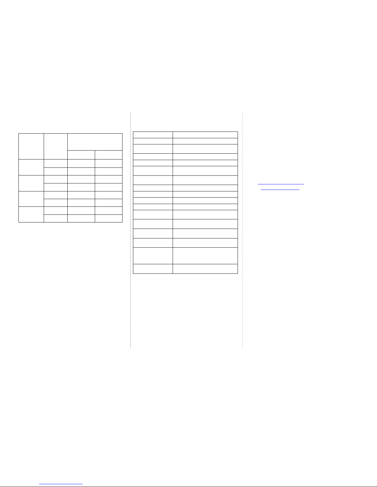
OPERATING
ONDITION
/MODE
TIMING
SEQUEN E
STATUS
RELAY LED
CH1
ON TIME RLY1 ON ON
OFF TIME RLY1 OFF OFF
CH2
ON TIME RLY2 ON ON
OFF TIME RLY2 OFF OFF
CH3
ON TIME RLY3 ON ON
OFF TIME RLY3 OFF OFF
CH4
ON TIME RLY4 ON ON
OFF TIME RLY4 OFF OFF
a) The Set time changed when timing in progre i effective for the next
cycle onward (after the completion of the off time of ch4).
b) The Set time changed when S1-S2 i open i effective for the immediate
timing irre pective of hold/re tart (i.e. Power i not interrupted).
c) The Range etting hall not be done in the forbidden area.
Technical Specification
Function Sequential timer with 4 channel .
Rated upply Voltage 240V AC
Operating voltage
range ± 10% of the rated voltage
Rated Frequency 50Hz ± 5%
Power con umption AC Approx. 20VA / 4W.
Control output 4 O/P'S (5A @ 250 VAC/28 VDC re i tive)
Start Signal (S1, S2) Potential free clo ure (CONTINUOUS).
On time range 0.1 to 1 S/M/H for each channel
Off time range 0.1 to 1 S/M/H for each channel
Setting accuracy ± 10 % max. w.r.t full cale ± 100 mSec
Repeat accuracy ± 1 % max. ± 100 mSec
Recovery Time 1Sec minimum
Variation due to
voltage change ± 2% max. ± 100 mSec
Variation due to
temperature change ± 5% max. ± 100 mSec
Variation due to
frequency change
± 2% max. ± 100 mSec
Ambient temperature Operating : -10
˚
C to +55
˚
C
Storage : -25
˚
C to +80
˚
C
Humidity MAX 85% RH @ 40
˚
C
Disposition
Once the product life i over, you may end Back the unit to
EAPL for di po ition.
ontact
Electronic Automation Pvt. Ltd
#20, KHB Indu trial area
Yelahanka
Bangalore -64
Ph:+91-80-28567561/2,/42802345
Cu tomer care :Ph:+91-80-42802323
Email : [email protected]
www.eaplindia.com
OD RK AN 050011 REV 02/24-05-2018 Page 2 of 2
Table of contents
Other EAPL Timer manuals


