Hattersley Fig.1051 User manual

Installation and Operating Instructions
Constant Flow Regulator (CFR)
Fig.1051
General Notes
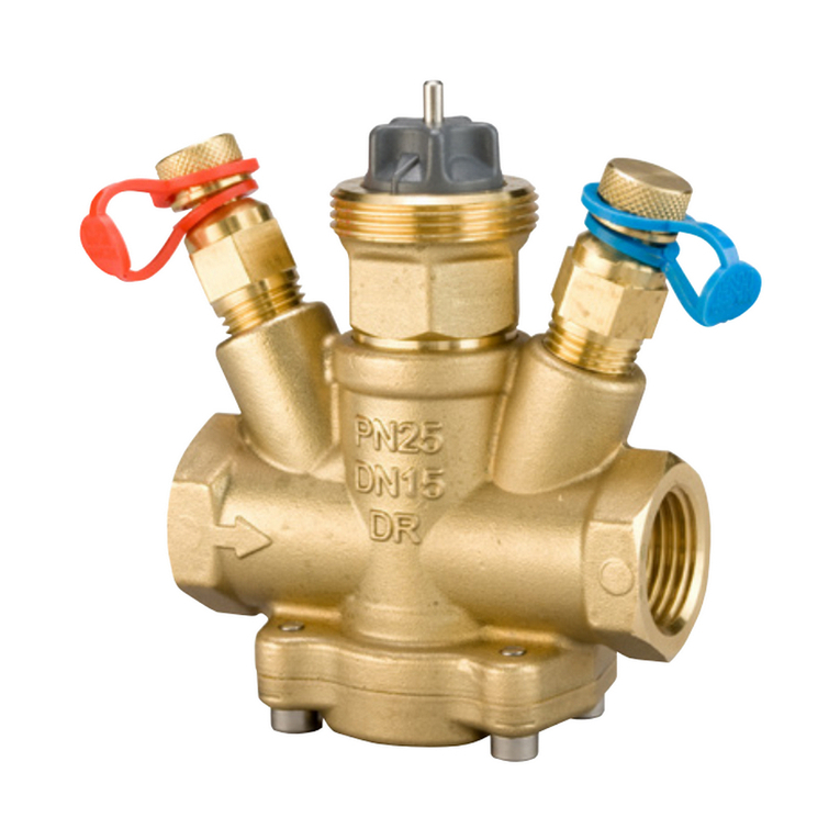
The Hattersley Fig.1051
• Can be used in variable volume heating
and chilled water systems.
• Has a double regulating feature allowing
the valve opening to be set with a 3mm
Allen key.
• Is operated by means of the handwheel
with position indicator or with
recordable set position.
• Has a linear control characteristic
across setting operating range.
• Has built in Differential Pressure
Control.
• HasamaximumworkingΔP=4bar
• Has built in pressure test points to verify
operational differential pressures.
Limit of Use
These valves have been categorised in accordance with the Pressure Equipment Directive
2014/68/EU.
The fluid to be transported is limited to group 2 liquids i.e. non-hazardous.
On no account must these valves be used on any group 1 liquids, group 1 gases, group 2
gases or unstable fluids.
Note: Valves are classified as SEP (sound engineering practice) and as such cannot be CE
marked and do not require a declaration of conformity.
Fig.1DN25/DN32Style(left)andDN40/DN50Style(right)

Hattersley Constant Flow Regulator02
Installation and Operating Instructions
Installation
These instructions are issued as guidelines only and do not cover all installed conditions. If unsure
pleasecontactourTechnicalHelplineon01473277400,beforeinstallation.
• It is advised that the valve should be installed in a run of pipe of the same nominal size.
• Hattersley products are designed for installation and use within suitably designed systems
reflectingCIBSE,BSRIAandHVACguidelines.Particularcareshouldbetakenwithregardsto;
oAccessibilitytovalveforsetting/adjustment
oTubecutting–aftercuttingandthreading,theendmustbedeburredorreamed
before fitting to the valve.
oJointing–nothreadjointingmaterialsmustbeallowedtoprotrudeinsidethebore.
oBracketing/supports–thepipingsystemshallprovidesuitablesupportandmustbe
carefully aligned and at the correct distance between centres for the size and type
of valve.
• Orientation: The Fig. 1051 can be positioned in any orientation.
• Normallyinstalledonreturnpipework,i.e.aftertheequipmentitiscontrolling,butcanbe
installed in flow if required.
• Ensure direction of flow is correct - indicated by an arrow on the valve body.
• Fig.1051 operates between a minimum and maximum pressure drop across the valve -
seecommissioningsectiononpage4.
• CFR’sarenotdesignedasisolationvalves.Dedicatedisolationvalvesshouldbeinstalled
toisolateagainstsystempressure,i.e.formaintenanceetc.,whendisconnecting/draining
pipework.
• Careshouldbetakentonotexceedmaximumoperatingdifferentialpressure,toprevent
damage to the internal components.
• SystemsshouldbeinstalledwithstrainerstoprotecttheCFRandotherinstalleditems.
• StraightlengthsofpipeworkarenotrequiredforCFR’sbutsomestraightlengthsare
recommended to create a more stable flow pattern.
Flushing
Controlvalves,liketheCFR,aresizedtogivegoodcontroloverthe
systemwater,therefore,havebeendesignedwithasmallconvoluted
flow path. These water ways may not allow adequate water velocities
forflushingofthecoil,evenwhenfullyopen.Therefore,inlinewith
BSRIArecommendations,itisrecommendedthataflushingpoint
belocatedbetweenthecoilandtheCFR.Thisallowsthecoiltobe
flushedwithoutthewaterpassingthroughtheCFR.
PleaserefertoBSRIAGuideBG29–2012forguidance.

Product Title Here
03Hattersley Constant Flow Regulator 03
Valve Setting Indicator
Fig.1051 valves operate from closed to fully
openwith4completeturnsofthehandwheel.
The handwheel indicates the valve setting by means
of digits in the outer (left) and inner (right) windows.
The digit in the inner window indicates tenths of a turn.
Theexampletotherightshowsavalvesettingof4-0
turns (fully open).
Regulator
Flowregulationisachievedbyadjustingthevalvesettinguntiltherequiredflowrateisobtained.
The‘Microset’handwheelwillindicatethefinalvalvesetting.Seetable1onpage4forflowrate
setting.
Setting Facility
The valve setting at which the required flow rate is achieved may be retained as follows:
1.Removecapincentreofhandwheel
2.UsingtheAllenkeyprovidedtightenthecentrescrewuntilitstops.
Do not over-wench.
3.Replacecentrecapinhandwheel.
Thevalveisnowsetandbeadjustedandre-settotheoriginalsetpoint.
Pressure Temperature Rating
Temperature °C -10 to 120
Pressure (Bar) 16

Hattersley Constant Flow Regulator 04
Installation and Operating Instructions
Commissioning
TheFig.1051controlstheflowratedependingonitssetposition,therefore,removingtheneedto
measure the flow rate.
TheFig.1051maintainsaconstantdifferentialpressureacrossitsinternalseat,anyexcess
pressure being removed by the internal differential pressure controller. To ensure that sufficient
pressureisavailableforthedifferentialpressurecontrollertocontroltheflowratecorrectly,a
differential pressure reading should be taken using the test points provided.
Whentakingdifferentialpressurereadings,itisimportantthatthesystemisrunningatfullload,
i.e.withCFR’ssettodesignflowrate.Thisensuresthatdifferentialpressurereadingsarecarried
outinthemostunfavourableconditions,guaranteeingoptimumperformanceinnormalrunning
conditions.
ToensurethatallCFRsareworkingattherequireddifferentialpressure,itisnecessarytocheck
theleastfavoured/indexCFR.ByverifyingtheleastfavouredCFRissetcorrectlythenallother
CFRsmusthaveahigherdifferentialpressure.However,wewouldalsorecommendthata
selectionofotherCFRsaretestedalongthecircuittoverifythis.
Differential Pressure Requirements
Ateach%settingoptionallsizesrequireaspecificconstantΔP(DifferentialPressure)toensure
theCFRiswithinitsworkingrange:
Table 1 - CFR Flow Rate Setting Table
H/W
Setting
%
Opening
FLOW RATE l/s
DN25 DN32 DN40 DN50
ΔP
Across
Test
Points
Activation
ΔP
Overall
(kPa)
Flow
Rate
l/s
ΔP
Across
Test
Points
Activation
ΔP
Overall
(kPa)
Flow
Rate
l/s
Activation
ΔP
Overall
Across
Test
Points
(kPa)
Flow
Rate
l/s
Activation
ΔP
Overall
Across
Test
Points
(kPa)
Flow
Rate
l/s
4.0 100.0 10 25 0.48 30 40 0.90 35 2.40 35 3.20
3.5 87.5 10 25 0.42 30 40 0.79 35 1.90 35 2.80
3.0 75.0 10 20 0.36 30 35 0.68 30 1.50 30 2.40
2.5 62.5 10 20 0.30 30 35 0.56 30 1.20 30 2.00
2.0 50.0 10 20 0.24 30 30 0.45 25 0.90 30 1.60
1.5 37.5 10 20 0.18 30 30 0.34 25 0.70 30 1.20
1.0 25.0 10 20 0.12 30 25 0.23 20 0.50 25 0.80
0.5 12.5 10 20 0.06 30 25 0.11 20 0.30 25 0.40
0.0 0.0 0 0 0.00 0 0 0.00 0 0.00 0 0.00

Forflowratesbetweensettings,interpolationofpositioncanbeused.
PleasenotethatDN25andDN32testpointsmeasurethedifferentialpressureacrosstheseat,
not overall pressure drop.
PleasenotefortheDN40andDN50thetestpointsmeasuretheoveralldifferentialpressuredrop
across the valve only.
The pump speed should be set to ensure that the required differential pressure is always
available.BysettingthedifferentialpressureacrosstheleastfavouredCFRtothevaluestated
intheabovetable,itensuresthatminimumpumpenergyisused,therefore,reducingsystem
running costs and CO2 emissions:
DN25 & DN32
To set pump speed to achieve this: whilst measuring ΔP (across test points), increase
pump speed until a constant ΔP is achieved, however please note that the typical ΔP
value, as shown in the table above, can differ but in itself is not critical to operation.
DN40 & DN50
To set pump speed to achieve this: whilst measuring ΔP (across test points), increase
pump speed until a value greater than the minimum stated in the above table is achieved.
As the measured ΔP is the total pressure drop across the PICV, the measured value will
continue to rise as pump speed is increased. Any value above the minimum requirement
will increase running costs, therefore, reducing system efficiency.
Theoptimumsettingisachievedwhenthereissufficient,butnotexcessive,pumppressure
available.
Flow rate verification should be carried out using separate Flow Measurement Devices (FMD)
wherefitted.InlinewithCIBSE&BSRIArecommendations,werecommendthatasaminimum
requirement,FMDsareinstalledinallbranches.
Installation and Operating Instructions
Hattersley Constant Flow Regulator5

Product Title Here
2
www.cranebsu.com
H_FIG.1051_1117
IOM_200054-000R01_v1
Every effort has been made to ensure that the information contained in
this publication is accurate at the time of publishing. Crane Ltd assumes
no responsibility or liability for typographical errors or omissions or
for any misinterpretation of the information within the publication and
reserves the right to change without notice.
• Designed and manufactured under quality management
systemsinaccordancewithBSENISO9001-2008
FM311ISO9001
POBOX719,IPSWICH,IP19DU
HOMESALES:+44(0)1473277410
EXPORTSALES:+44(0)1473277450
TECHNICALHELPLINE:08456041790
FAX:+44(0)1473277411
EMAIL: [email protected]
EMAIL: [email protected]
www.hattersley.com
Table of contents
Other Hattersley Control Unit manuals
Popular Control Unit manuals by other brands
HomeMatic
HomeMatic HM-PB-2-WM Installation and operating manual
LiteOn
LiteOn WN4501L user manual

BYOC
BYOC Crown Jewel Hard Clipper instructions

PHOENIX DIGITAL
PHOENIX DIGITAL OCM-DPR-1 Installation and user manual
DeZurik
DeZurik VPB V-PORT instruction manual
A.R.I.
A.R.I. D-070-P Installation operation & maintenance
