hattrick KP-1100 User manual
0
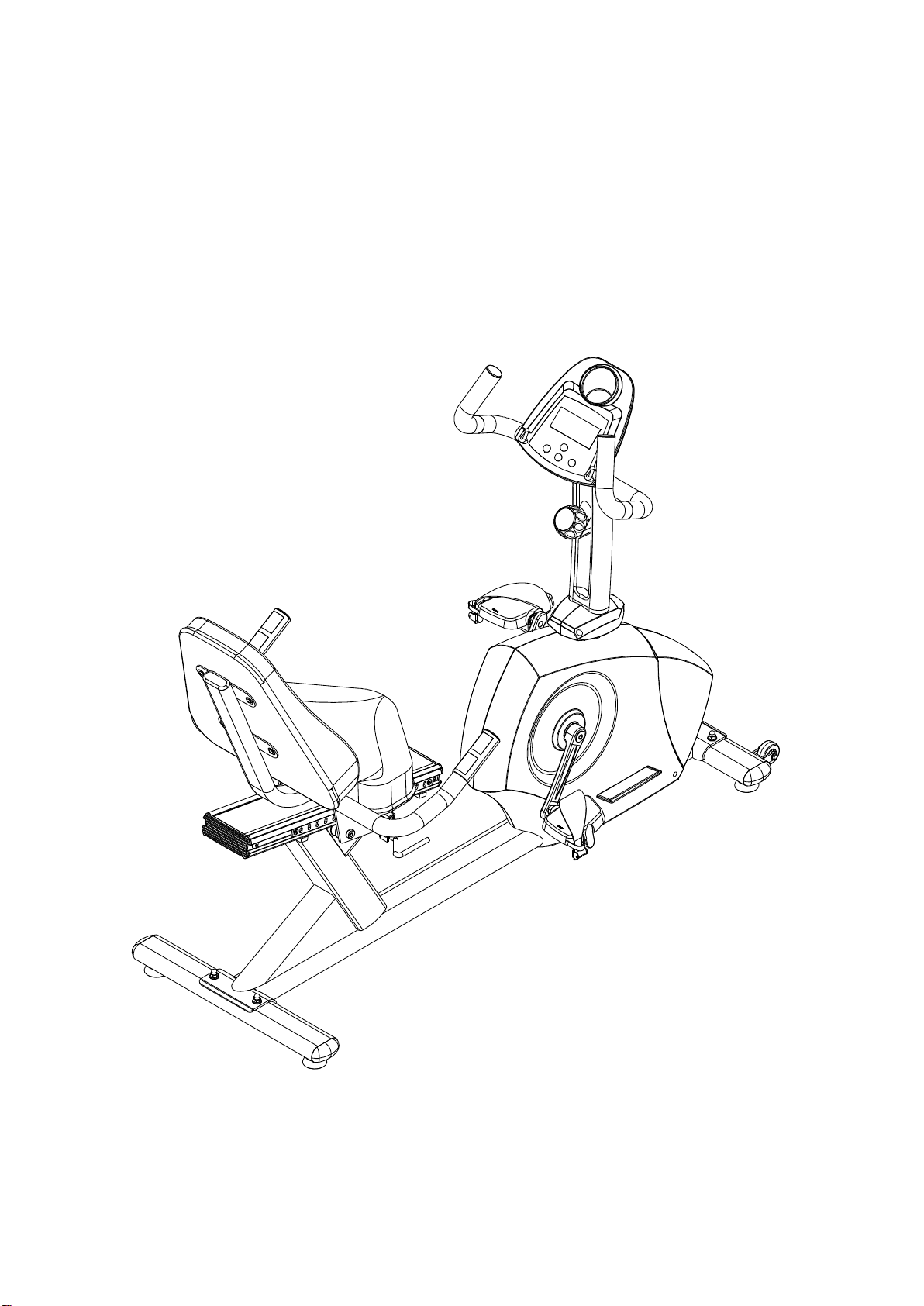
KP-1100 RECUMBENT BIKE USER MANUAL

TABLE OF CONTENTS
PRODUCT SAFETY ---------------------------------------------------------- 1
PART DRAWING --------------------------------------------------------------2
PART LIST ---------------------------------------------------------------------- 3
ASSEMBLY --------------------------------------------------------------------- 4
TROUBLE SHOOTING & MAINTENANCE ----------------------------- 8
WARM UP -----------------------------------------------------------------------9
EXPLODED VIEW -------------------------------------------------------------10

Basic precautions should always be followed, including the following safety
instructions when using this equipment: Read all instructions before using this
equipment.
1. Read all the instructions in this manual and do warm up exercises before using this
equipment.
2. Before exercise, in order to avoid injuring your muscles, warm-up exercise for every
muscle group is highly recommended. Please refer to the Warm Up pages for pre
and post workout.
3. Please make sure all components are not damaged and in working order before
use. This equipment should be placed on a flat surface while in use. Using a
mat or other material on the ground is recommended.
4. Please wear proper clothes and shoes when using this equipment; do not wear
clothes that might catch in any part of the equipment.
5. Do not attempt any maintenance or adjustments other than those described in this
manual. Should any problems arise, discontinue use and consult an Authorized
Service Representative.
6. Do not use the equipment outdoors.
7. This equipment is for household use only.
8. Only one person should be on the equipment while in use.
9. Keep children and pets away from the product while in use. This machine
is designed for adults only. If you feel any chest pains, nausea, dizziness, or short
of breath, you should stop exercising immediately and consult your physician
before continuing.
WARNING: Before beginning any exercise program consult your physician. This is
especially important for the persons who are over 35 years old or who have
pre-existing health problems. Read all instructions before using any fitness
equipment.
CAUTION: Read all instructions carefully before operating this product. Retain this
Owner’s Manual for future reference.
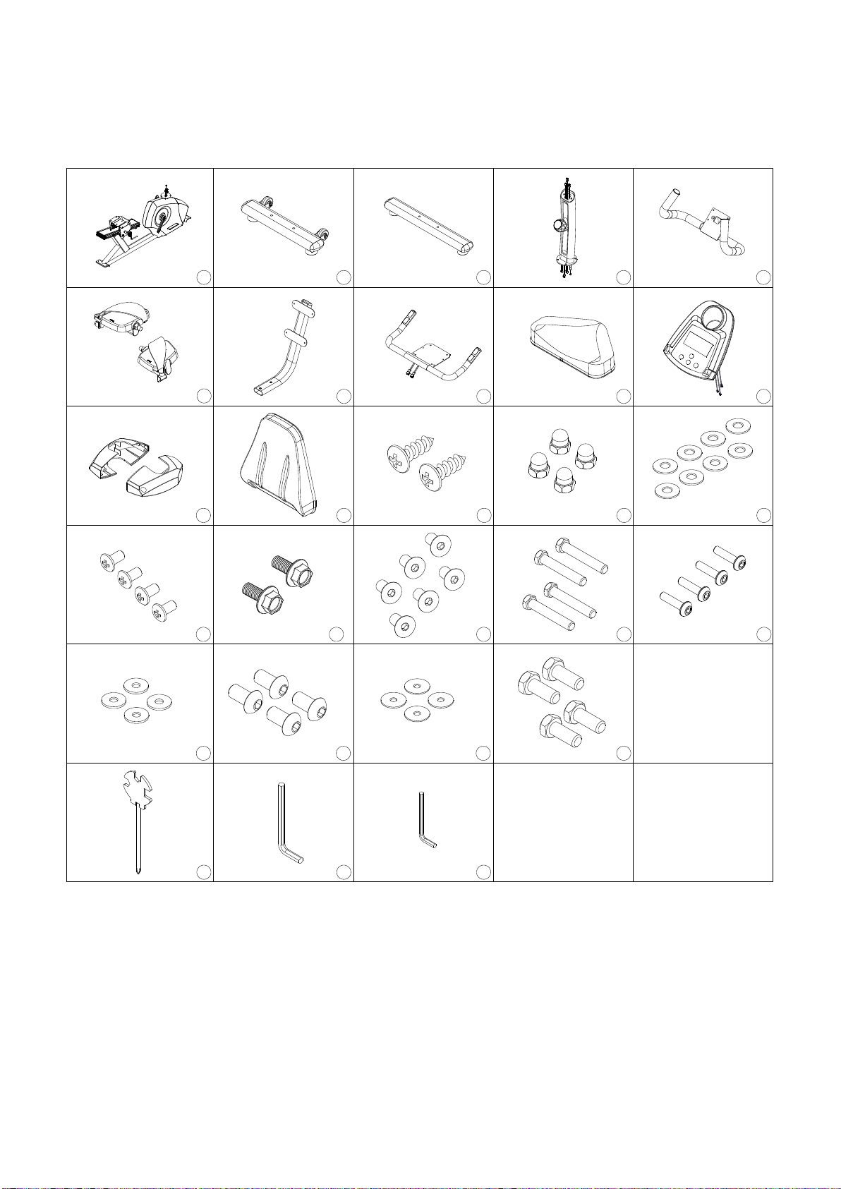
Parts Drawing
123 4 5
68910
11 12
7
181716
13 14 15
19 20
21 22 23 24
25 26 27

Parts List
Item No.
Description
Qty.
1
Main Frame
1 PC
2
Stabilizer-Front
1 PC
3
Stabilizer-Rare
1 PC
4
Upright Tube
1 PC
5
Hand Bar
1 PC
6
Pedal
1 SET
7
Back Tube
1 PC
8
Seat Assembly
1 PC
9
Upholstered, Seat
1 PC
10
Computer
1 PC
11
Upright Joint Cover
1 SET
12
Upholstered, Backrest
1 PC
13
Self Tapping Screw M5x16L
2 PCS
14
Dome Nut 3/8"
4 PCS
15
Washer 20x3/8"x2.0T
8 PCS
16
Bolt For Computer
4 PCS
17
Hex Bolt M8x25L
2 PCS
18
Hex Bolt M8x25L
6 PCS
19
Hex Bolt 3/8"x64L
4 PCS
20
Hex Bolt M6x20L
4 PCS
21
Washer 1/4"x19x2.0T
4 PCS
22
Hex Bolt M8x12L
4 PCS
23
Washer 8x16x1.5T
4 PCS
24
Hex Bolt M8x25L
4 PCS
25
Tool
1 PC
26
Wrench 5mm
1 PC
27
Wrench 4mm
1 PC

Step 1. Rare Stabilizer Installation
Attach the Rare Stabilizer (3) onto the front curve of the Main Frame with two 3/8"
Bolts (19), four 3/8” Washers (15), and two 3/8"Dome Nuts (14).
Tighten bolts with tool provided.
Step 2. Front Stabilizer Installation
Position the Front Stabilizer (2) in front of Main Frame and align bolt holes.
Attach the Front Stabilizer (2) onto the front curve of the Main Frame with two
3/8" Bolts (19), four 3/8” Washers (15), and two 3/8"Dome Nuts (14).
Tighten bolts with tool provided.
3
19
14
15
2
15
19
14
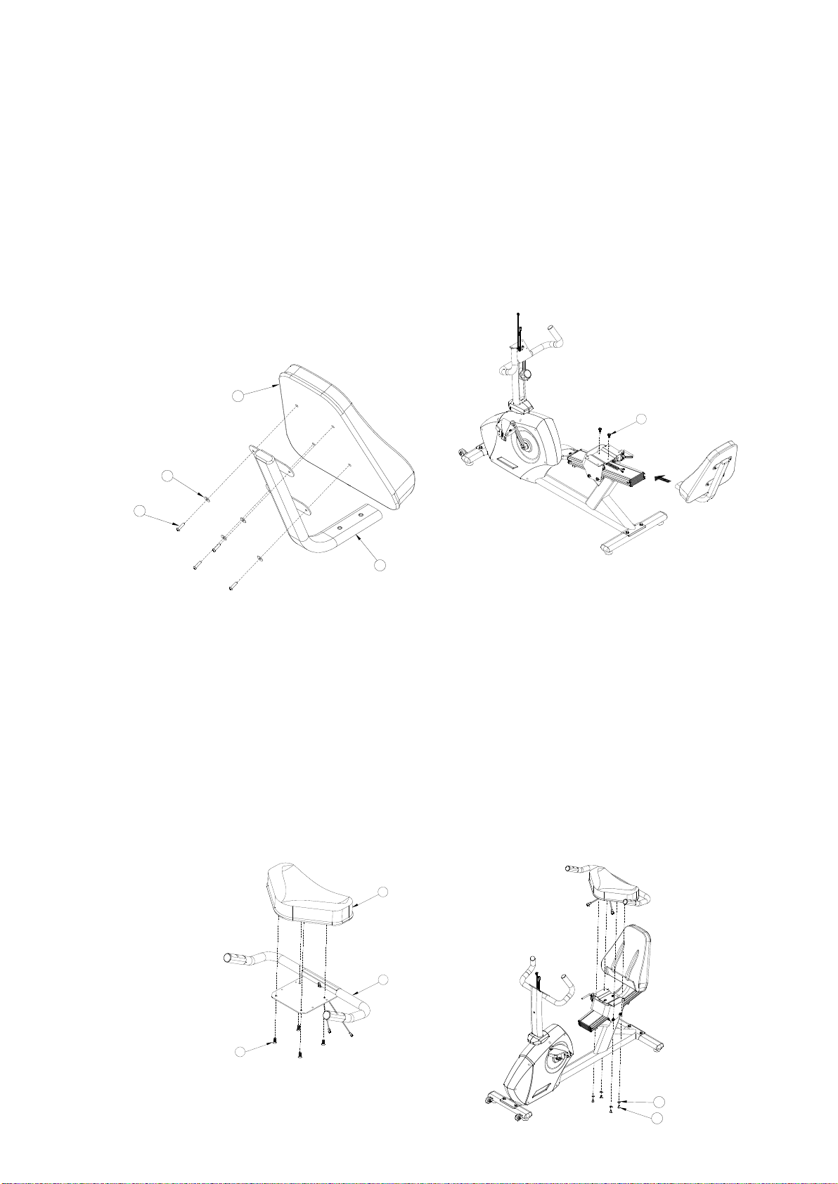
Step3 . BackRest and Seat Assembly
Assemble the backrest(12) to the Backrest Tube(7) with aligning the four screw holes
to the holes at the bracket of the Backrest Tube(7). Use four Washers(21) and Bolt(20)
and tighten the bolts on the Backrest Tube(7). Assemble the Backrest Tube to the
Seat Bracket with two Bolt(17).
Align the four holes of the Seat(9) to the holes of the Seat Frame(8). Use four Bolts(18)
tightening the Seat.
Connect the connector of the coiled hand pulse sensor cable to the hand pulse sensor
cable of the handle bar.
Connect the Seat Assembly to the Seat Frame with four Washers(23) and four
Bolts(22).
21
20
7
12
17
23
22
9
8
18

Tighten all Bolts with the tool provided.
Step 4 Upright Tube Assembly
Lift the Upright Tube(4) to the top of the Main Frame, connect the Computer Cable
carefully. Slide the Computer Cable into the hole of the Main Frame.
Make sure that all cables are not pressed by the Upright Tube while assembling.
Align four screw holes with the bracket of the Main Frame. Use four M8 Bolts(24)
securing the Upright Tube to the Main Frame.
Tighten all bolts with the Wrench included.
24
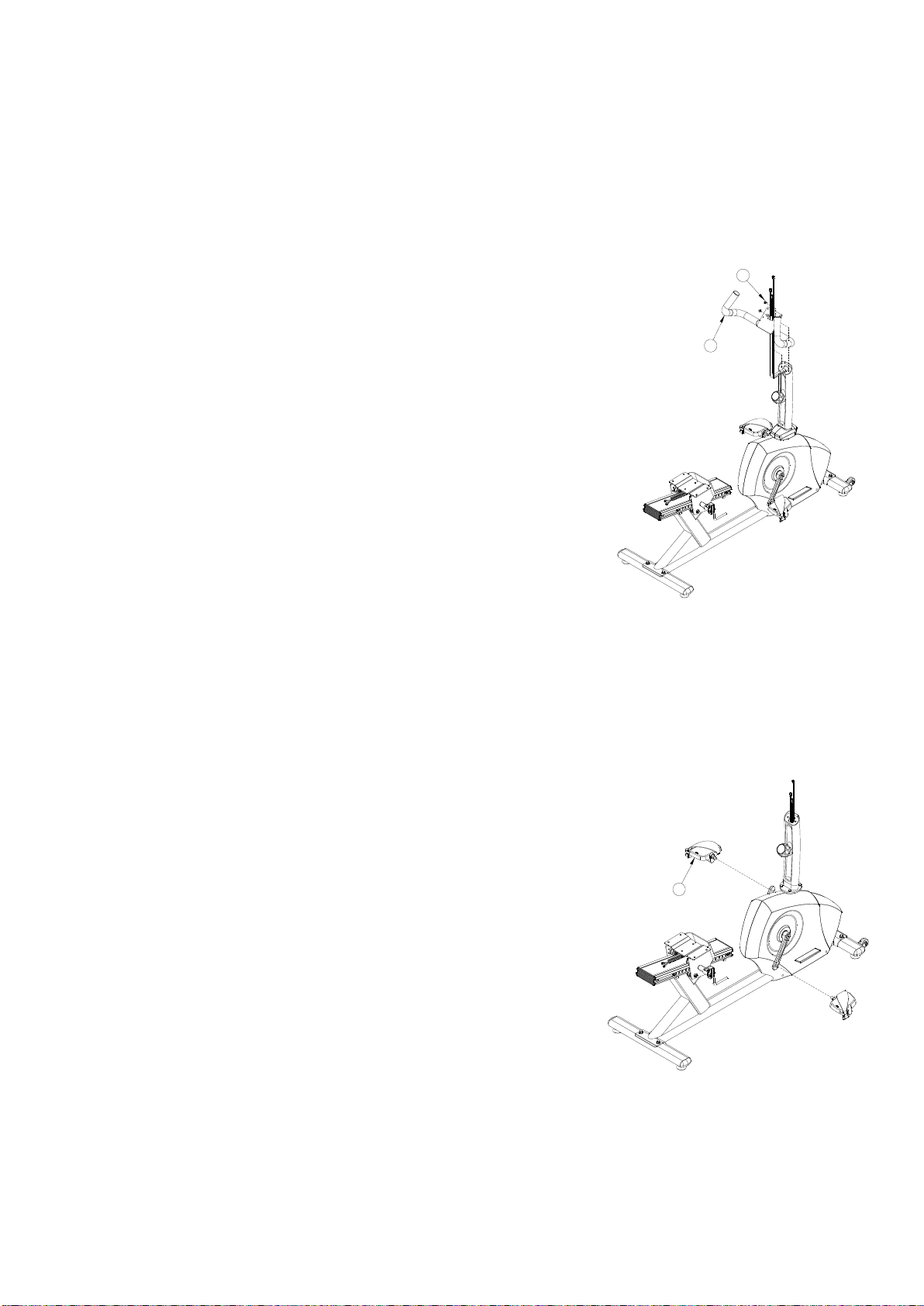
Step 5 Handle Bar Post Assembly
Route the Computer and the Hand Pulse Cable from
the Handle Bar Post(5) to the Hole at the Bracket of
Computer Bracket.
Use two M8 Bolts(18) to attach the Handle Bar Post to the
Upright Tube.
Tighten all bolts with the wrench included.
Step6 Foot Pedal Assembly
Screw the screw of the Right Foot Pedal(1 of 6) to the thread of the Right Crank.
Repeat the same procedure to the Left Foot Pedal(2 of 6) to the Left Crank.
Tighten Foot Pedal with the wrench included.
5
18
6
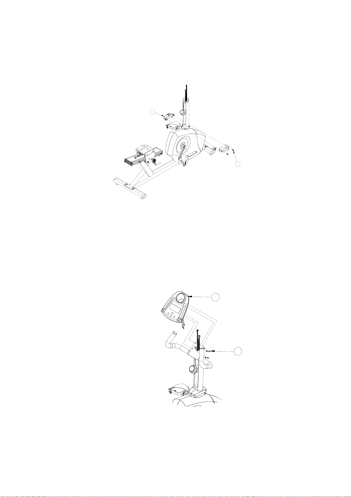
Step 7 Upright Joint Cover Assembly
Joining the Left and Right Upright Joint Cover(11) onto the brackets of the Upright
Bar and the Main Frame. Use two M5 Self Tapping Screw(13) tightening all four
screws.
Step 8 Computer Assembly
Connect the Computer Cable and the Hand Pulse Cables with the plugs at the
Computer(10). Slide all Cables into the hole of the Upright Tube. Use four
Computer Screws(16) holding the Computer(10) on
the bracket of the Upright Bar.
13
11
16
10

Trouble Shooting
Adjusting the Adjustable Leveler
Turn the Adjustable Levelers (C05) on the Front Stabilizer (2) and Rare Stabilizer(3)
as needed to level the upright bike. The bike has to be leveled to prevent from
wobble or shaking during the exercise.
MAINTENANCE
Cleaning
The Upright Bike can be cleaned with a soft cloth and mild detergent. Do not use
abrasives or solvents on plastic parts. Be careful not get excessive moisture on the
computer display panel as this might cause an electrical hazard or electronics to fail.
Please keep the Upright Bike, specially, the computer console, out of direct sunlight to
prevent screen damage. Please inspect all assembly bolts and pedals on the
machine for proper tightness every week.
Storage
Store the elliptical trainer in a clean and dry environment away from children.
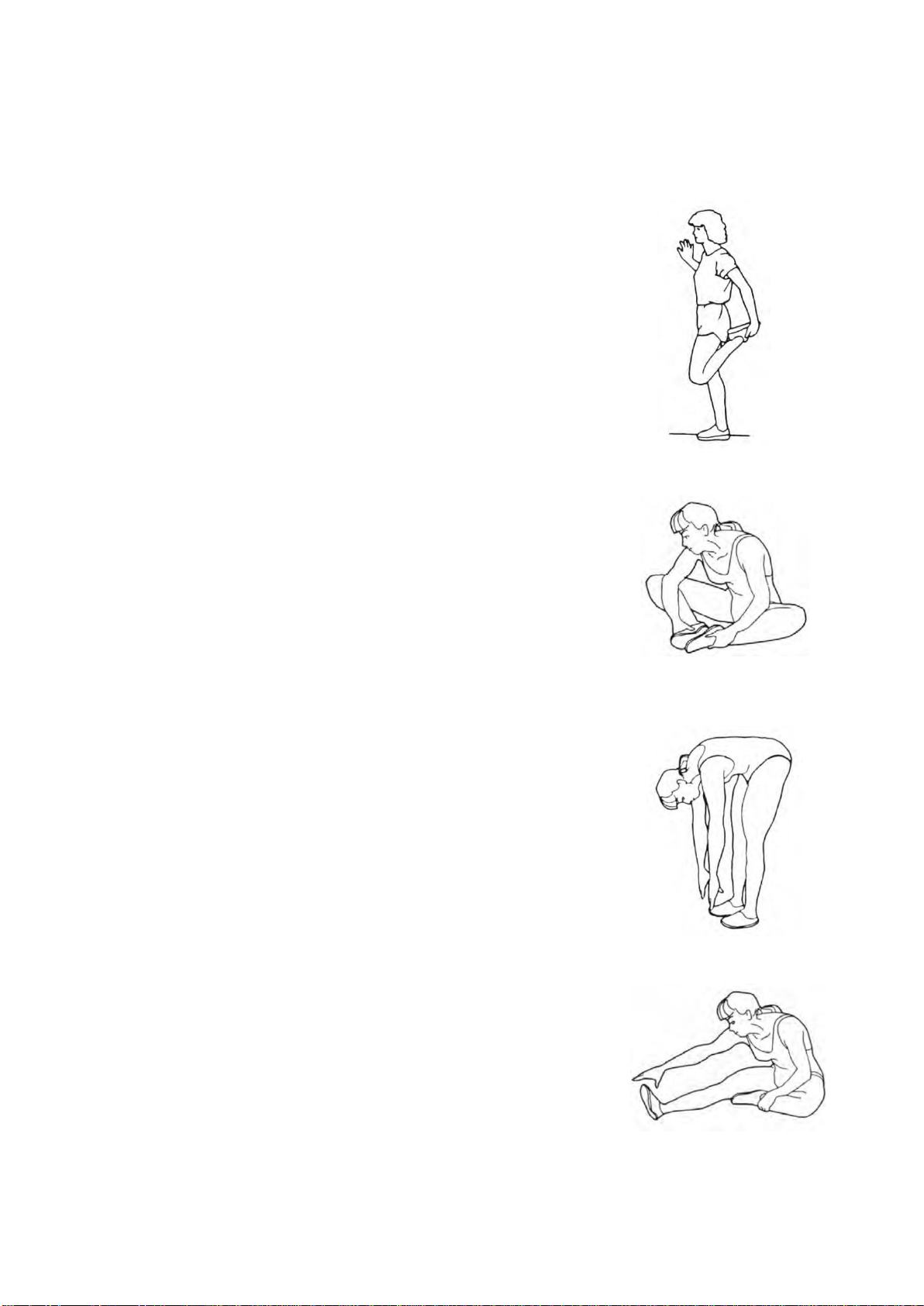
WARM UP
Quadriceps Stretch
With one hand against a wall for balance, reach behind
you and pull your right foot up. Bring your heel as close
to your buttocks as possible. Hold for 15 counts and
repeat with left foot up.
Inner Thigh Stretch
Sit with the soles of your feet together with your knees
pointing outward. Pull your feet as close into your groin
as possible.
Gently push your knees towards the floor. Hold for 10
counts.
Toe Touches
Slowly bend forward from your waist, letting you back and
shoulders relax as you stretch toward your toes. Reach
down as far as you can and hold for 15 counts.
down as far as you can and hold for 15 counts.
Hamstring Stretches
Sit with your right leg extended. Rest the sole of your left
foot against your right inner thigh. Stretch toward your
toe as far as possible. Hold for 15 counts Relax and then
repeat with left leg extended.
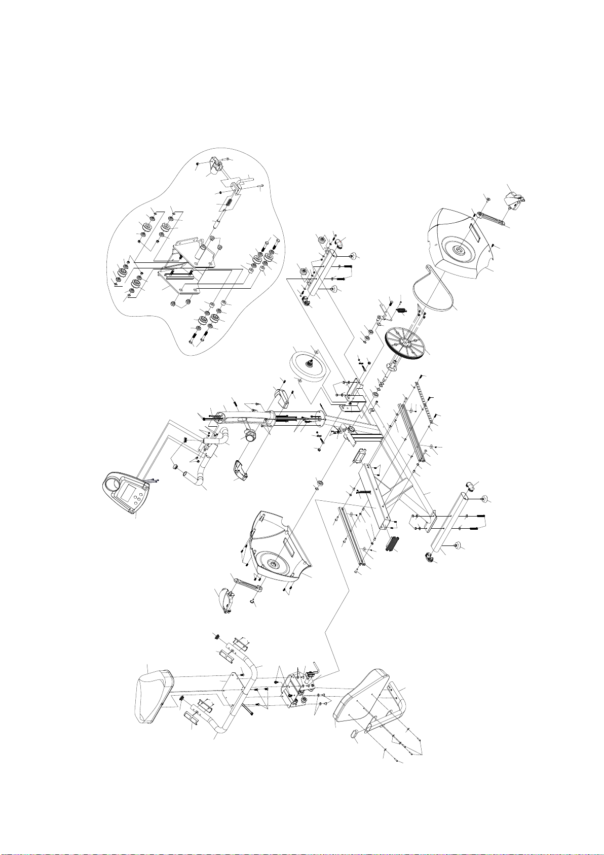
Exploded View
F01
F02
E02
E02
E01
E01
D04
D03
D02
C17
C16
C16
C16
C16
C16
C16
C16
C16
C12
C10
C20
C19
C19
C18
C18
C18
C18
C14
C15
C13
C11
C11
C09
C08
C07
C07
C06
C06
C05
C05
C05
C05
C04
C04
C04
C04
C02
C03
C01
C01
A01
A02
A03
A10
A05 A06
A07
A08
A09
A04
B01
B02
B02
B03
B05
B04
B06
B06
B07
B07
B08
B08
B09
B10
B11B12
B13
B13
B17
B17
B18
B19
B20
B21
B22
B23
B23
B23
B23
B24
B24
B25
B25
B25
B25
B26
B27
B28
B29
B29
B29
B29
B29
B29
B29
B30
B30
B31
B32
B32
B32
B32
B33
B33
B34 B35
B35
B35
B36
B36
B36
B37
B37
B37
B37
B37
B38
B38
B39
B39
B39
B39
B40
B41
B42
B43
B44
B45
B46
B46
E03
E03
E03
E03
E03
E03
E03
E03
E03
E03
E03
E03
E03 E03
E03
E03
B47
B47
B48
B48
B49
B50
B50
B51
B51
B51
B53
B01
B01
B54
B53
B54
B53
B16
B15
B15
B15
B15
C13
B14
D05
B52
B52
B38
B38
B29
B29
C01
B55
B55
B55
B55
D06
D08
D07
D09
D10
D01
D03
B18

Part No
Description
Q'ty
Part No
Description
Q'ty
A01
welded,main frame
1
B41
socket screw M5x0.8Px25L
1
A02
welded,upright tube
1
B42
welded,fixed seat
1set
A03
welded,slide Assembly
1
B43
locknut M5
1
A04
welded,hand bar
1
B44
spring
1
A05
welded,shaft pulley
1
B45
lock pin
1
A06
welded,pressure assembly
1
B46
locknut M8
4
A07
welded,Back Tube
1
B47
hex bolt M8x1.25px45L
4
A08
Stabilizer-rare
1
B48
pulley shaft
4
A09
welded,stabilizer-front
1
B49
socket screw M6x1.0Px30L
1
A10
welded,seat assembly
1
B50
hex bolt M6x1.0px20L
4
B01
hex screw M8x1.25x25L
6
B51
washer ψ1/4"xψ19x2.0T
4
B02
hex screw 1/4"x1 3/4"
2
B52
hex screw M5x0.8Px10L
4
B03
locknut 1/4"
2
B53
hex bolt M8x1.25px10L
4
B04
crank
1
B54
washer ψ8xψ16x1.5t
4
B05
crank
1
B55
washer ψ5/16"xψ20x2.0t
4
B06
hex screw M8x1.25Px25L
4
C01
plug ψ31.8
4
B07
dome nut 3/8"
4
C02
main cover-right
1
B08
nut 3/8 UNC-26
2
C03
main cover-left
1
B09
socket screw M10x1.5px25L
1
C04
plug 40x80
4
B10
hex screw M8x1.25px10L
4
C05
height adjuster foot M8
4
B11
washer ψ23xψ20x1.0t
1
C06
wheel-stabilizer front
2
B12
wave washer ψ20
2
C07
pedal
1set
B13
hex screw M8x1.0x29L
2
C08
belt
1
B14
philips self drive screw
M5x16L
1
C09
drive pulley
1
B15
pulley space
4
C10
upholstered,backrest
1
B16
hex screw M8x1.25Px25L
2
C11
rubber grip
2
B17
bolt
2set
C12
plug 30x70
1
B18
philips screw M3x25L
4
C13
rubber grip
2
B19
locknut M10
1
C14
upright joint cover-right
1
B20
C clip
1
C15
upright joint cover-left
1

B21
C clip
1
C16
plastic pulley
8
B22
washer ψ10xψ27x2.0t
1
C17
gripping sheath
1
B23
washer ψ1/4"xψ16x1.5t
4
C18
pvc pad
4
B24
hex bolt 3/8"x57L
4
C19
plug
2
B25
washer ψ20xψ3/8”x2.0t
8
C20
upholstered,seat
1
B26
extension spring
1
D01
computer ST-8910
1
B27
socket screw M8x1.25px16L
1
D02
flywheer with magnet
1
B28
hex screw M6x1.0px16L
1
D03
hand pulse sensor with cable
2set
B29
self tapping screw M5x16L
15
D04
10step resistance computer
1
B30
washer ψ10xψ25x3.0t
2
D05
computer cable with sensor
1
B31
philips screw M5x0.8Px40L
1
D06
computer cable
1
B32
pulls hat M8
5
D07
tension cable with adjuster
1
B33
pulls hat M6
3
D08
hand pulse cable-upside
2
B34
lock pin plate
1
D09
hand pulse cable-center
2
B35
screw M6x1.0px35L
3
D10
hand pulse cable-lower
2
B36
lock pin space
3
E01
bearing 6004
2
B37
hex screw M8x1.25px30L
5
E02
bearing 6003
2
B38
space
5
E03
bearing 608
16
B39
philips screw M4x0.7Px8L
4
F01
aluminum track left
1
B40
locknut M6
1
F02
aluminum track right
1
Popular Exercise Bike manuals by other brands


Fitnex
Fitnex ber30 user manual

Christopeit Sport
Christopeit Sport BLUE T1 Assembly and exercise instructions

Sunny
Sunny SF-B1002C owner's manual

Diamondback
Diamondback 300U Owner's manual and assembly guide

Tunturi
Tunturi C55-F user manual

Sunny Health & Fitness
Sunny Health & Fitness SF-B1709 user manual


