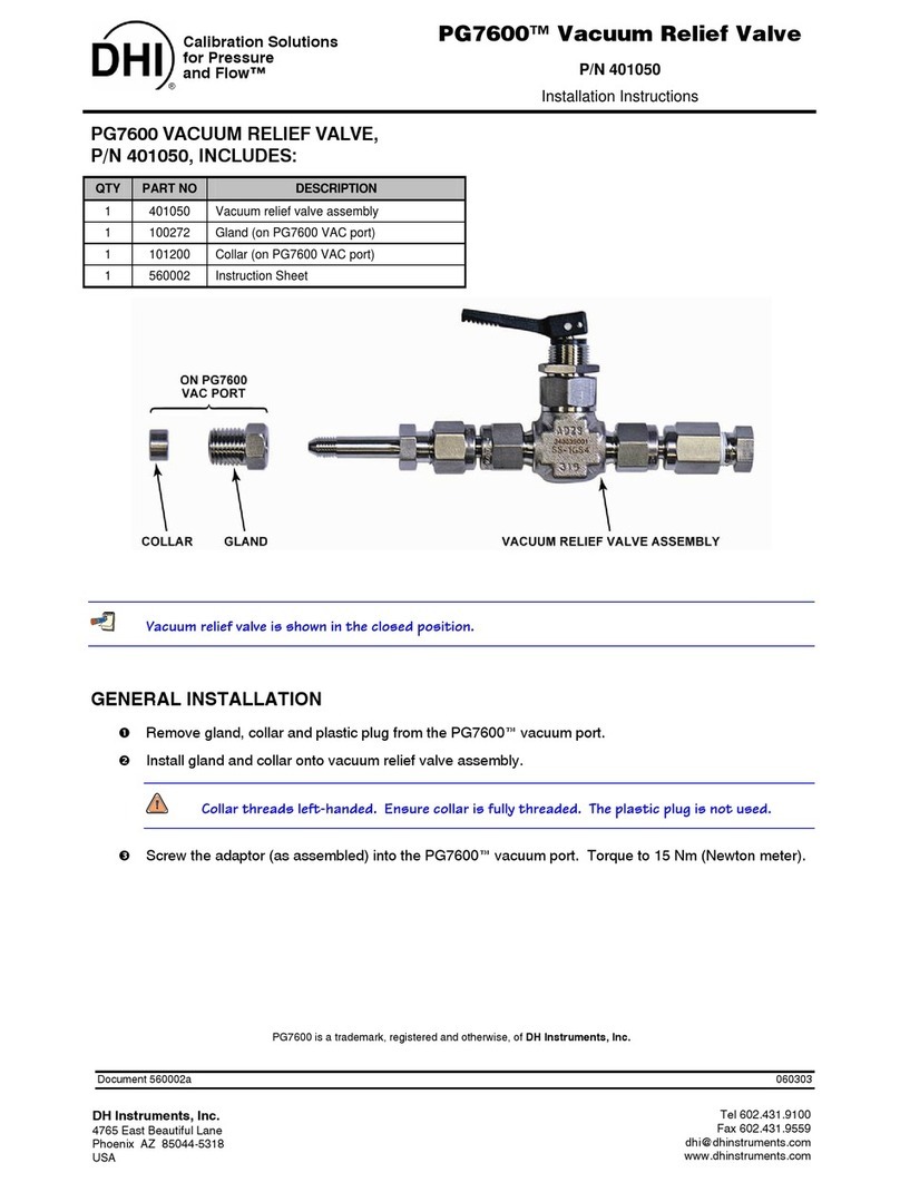
HAUTAU GSM 1 User manual

Technische Daten
07/2010 225772A
Montage- und
Betriebsanleitung
Gruppensteuermodul GSM 1
Installation and
operating instructions
Group control module GSM 1
Betriebsspannung 21 bis 32 V DC
Sicherung T 4 A
max. Ausgangsstrom 4 A
Relative Einschaltdauer 100%
Umgebungstemperatur -20 bis +50 °C
Schutzart IP 52 (Gehäuse)
Abmessungen Platine L x H x T 65 x 65 x 17 mm
Abmessungen Gehäuse B x H x T 96 x 96 x 40 mm
Mitglied im Fachkreis
elektromotorisch
betriebene Rauch und
Wärmeabzugsanlagen
© HAUTAU GmbH
Nachdruck, auch auszugsweise, nur mit schriftlicher Genehmigung des Herausgebers.
Im Sinne des Fortschritts behalten wir uns Konstruktionsänderungen und dadurch bedingte Abweichungen von Abbildungen, Abmessungen, Leitungsangaben
usw. vor. Die Abbildungen zeigen die Artikel nicht in natürlicher Größe und stehen auch nicht im gleichen Verhältnis zueinander.
© HAUTAU GmbH
Reprint, even in excerpts, not without the publisher’s approval.
In consideration of progress, we reserve the right to apply construction modifications and to consequently change any figures, dimensions, wire specifications
etc. The figures do not show items in their actual size and are also not of the same proportion.
Technical specifications
Operating voltage 21 to 32 V DC
Fuse T 4 A
max. output current 4 A
Duty cycle 100 %
Ambient temperature 20 to +50°C
Protection class IP 52 (housing)
Dimensions Circuit board W x H x D 65 x 65 x 17 mm
Dimensions Housing W x H x D 96 x 96 x 40 mm

2
Sicherheits- und
Montagehinweise
Leistungsbeschreibung
Montage intern TF 04 bzw. TF 08K
Internal installation TF 04 or TF 08K
Alle Arbeiten an netzspannungsführenden Bauteilen dürfen
nur durch eine Elektrofachkraft durchgeführt werden.
Sicherheitshinweise, die Sie beachten müssen:
Die DIN-, VDE-, Vorschriften der Berufsgenossenschaften
und die Vorschriften der örtlichen Energieversorgungs-
unternehmen sind zwingend zu beachten.
Bei Arbeiten an der Steuerung ist die Netzspannung
abzuschalten.
Gegen unbeabsichtigtes Wiedereinschalten ist die Anlage
abzusichern. Für die Netzzuleitung ist eine separate und
gekennzeichnete Vorsicherung vorzusehen.
Alle Leitungen, die 24 V DC führen, sind nicht mit Stark-
stromleitungen zu verlegen (VDE-Vorschriften beachten).
Die Leitungslängen und Leitungsquerschnitte sind gemäß
den technischen Angaben auszuführen.
Quetsch- und Scherstellen zwischen Fensterflügeln und
Rahmen, Lichtkuppeln und Aufsatzkranz müssen bis zu
einer Höhe von 2,5 m durch Einrichtungen gesichert sein,
die bei Berührung und Unterbrechung durch eine Person,
die Bewegung zum Stillstand bringt Richtlinie für kraft-
betätigte Fenster, Türen und Tore der Berufsgenossen-
schaften). Nach der Installation der Anlage sind alle Funktio-
nen und der Schwenkbereich des Antriebs zu überprüfen.
Für Lüftungssteuerungen in Kompaktbauweise (TF 04,
TF 08K) mit Gruppensteuermodul GSM 1 intern, sowie für
Netzteile (TF 02, TF 08, TF 16 und TF 24) mit Gruppen-
steuermodul GSM 1 extern.
Für jede Lüftungsgruppe wird ein Gruppensteuermodul
GSM 1 benötigt.
An ein GSM 1 können ein oder mehrere Lüftungstaster,
Thermostat, Raumhygrostat oder Fremdansteuerung (nur
eine Komponente möglich) und Regenmelder angeschlos-
sen werden.
Die maximale Belastung beträgt 4A.
- Der Lüftungstaster hat die geringste Priorität.
- Thermo-/ Hygrostat mit Steuereingängen Auf/Zu oder
Fremdansteuerung sind dem Lüftungstaster übergeordnet.
- Höchste Priorität hat der Regenmelder; das Steuersignal
ist Zu.
Safety and installation
information
Performance description
Any work on live components may only be performed by a
trained electrician.
Safety information to be observed:
Observing DIN, VDE and government safety organisation
regulations as well as the provisions of your local power
company is mandatory. Disconnect the mains supply before
performing any work.
The installation must be protected against accidental actua-
tion. A separate and marked prefuse must be installed for
the feeder wire.
No wires conducting 24 V DC must be laid together with
electric power lines (follow VDE regulations).
All wire lengths and cross sections must correspond with
the technical specifications. Crush and shear points
between window sashes and frames, light domes and metal
curb must be secured up to a height of 2,5 m by devices
that will stop the movement by the touch or interruption of a
person (guideline issued by the government safety organisa-
tion for powercontrolled windows, doors and gates).
After the system has been installed successfully, all
functions and the pivoting range of the drive must be
checked.
For ventilation control systems in compact design (TF 04,
TF 08K) with internal group control module GMS 1 and
power supply units (TF 02, TF 08, TF 16 and TF 24) with
external group control module GSM 1.
Each ventilation group requires one group module GSM 1.
You can connect one or several ventilation pushbuttons,
thermostats, room hygrostats or thirdparty activation
controls (only one component at a time) and rain sensors to
one GSM 1.
The maximum load is 4 A.
The ventilation pushbutton is given lowest priority.
Thermostat/hygrostat with control inputs Open/Close or
thirdparty activation is superordinate to ventilation push-
buttons.
Highest priority is given to rain sensor; control signal is
Close.
erst Distanzplatte ...
first distance plate ...
... dann Steuerung
... then control system

3
Die Abbildung zeigt eine Lüftungssteuerung in einer
Lüftungsgruppe bestehend aus:
TF 02 und einem externen Gruppensteuermodul GSM1.
Aufrüsten ist möglich mit einem weiteren externen GSM 1
bis max. 2A gesamte Stromaufnahme.
ohne Abbildung
Oben aufgezeigte Möglichkeit kann auch mit größeren
Netzteilen (TF 08, TF 16 u. TF24) und mehreren externen
Gruppen-steuermodulen aufgebaut werden, so das die
Steuerung direkt vor Ort montiert werden kann.
Eine weitere Möglichkeit zeigt diese Abbildung TF 04+2 in
einer Lüftungsgruppe bestehend aus:
TF 04 und einem Gruppensteuermodul GSM 1 intern
montiert. Aufrüsten auf weitere Lüftungsgruppen ist möglich
mit einem internen GSM 1 und externen GSM 1 bis max. 4A
gesammte Stromaufnahme.
Diese Abbildung zeigt eine Lüftungssteuerung in zwei
Lüftungsgruppen bestehend aus:
TF 08K und zwei Gruppensteuermodulen GSM 1 montiert.
Aufrüsten ist möglich mit weiteren externen GSM 1 bis max.
8A.
Wird nur eine Lüftungsgruppe benötigt, kann der freie Platz
mit einer Steuerung erweitert werden.
Anwendungsmöglichkeiten
The figure shows a ventilation control system installed in a
ventilation group consisting of:
TF 02 and an external group control module GSM 1.
The system can be upgraded with an additional external
GSM 1 with a total current consumption of up to 2 A.
No image
The option described above can also be set up with larger
power supply units (TF 08, TF 16 and TF 24) and several
external group control modules, allowing you to install the
control system directly on site.
Another option is shown in this figure: TF 04+2 installed in
one ventilation group consisting of:
TF 04 and one internal group control module GSM 1.
Upgrades to additional ventilation groups can be achieved
with one internal and one external GSM 1 with a total
current consumption of up to 4 A.
This figure shows a ventilation control system installed in a
ventilation group consisting of:
TF 08K and two GSM 1 group modules. Upgrades are
possible with an additional external GSM 1 with up to 8 A.
If only one ventilation group is required, the available slot
can be expanded with a control system.
Possible applications
erst Distanzplatte ...
first distance plate ... ... dann Steuerung
... then control system
erst Distanzplatte ...
first distance plate ...
... dann Steuerung
... then control system

Anwendungsbeispiele
3 Lüftungsgruppen, Thermostat, 2 Lüftungstaster,
1 Lüftungstaster mit Umschaltung Hand/Automatik und
einem Regenmelder für alle GSM 1 übergeordnet.
3 Lüftungsgruppen, Lüftungstaster mit Umschaltung
Hand/Automatik ,Thermostat je Gruppe und einem Regen-
melder für alle Gruppen übergeordnet “ZU”.
Application examples
3 ventilation groups, thermostat, 2 ventilation pushbuttons,
1 ventilation pushbutton with manual/automatic switching
and a rain sensor superordinate to all GSM 1.
3 ventilation groups, ventilation pushbutton with manual/
automatic switching, thermostat per group and rain sensor
for all groups superordinate to “CLOSE”.
HAUTAU GmbH · Postfach 1151 · D 31689 Helpsen
Fon +495724/393-0 · Fax Sales GLT -124 (domestic) / -138 (export)
Info@HAUTAU.de · www.HAUTAU.de
LT LT LTA
TH 010 REM/H10
24 V DC 24 V DC 24 V DC
24 V DC
LTA LTA LTA
TH 010 TH 010 TH 010 REM/H10
Thermostat Thermostat Thermostat
Thermostat
Table of contents
Other HAUTAU Control Unit manuals
Popular Control Unit manuals by other brands

CALEFFI
CALEFFI 145 Series Installation and commissioning manual

MYiR
MYiR MYC-YT507H product manual
4ms Company
4ms Company QCD Expander user manual
Sierra Wireless
Sierra Wireless AirPrime WP7504 Hardware integration guide

Audipack
Audipack 261511 manual
Automationdirect.com
Automationdirect.com Productivity 2000 P2-08TD1S manual

Chamberlain
Chamberlain LiftMaster Professional CB124 instructions
Bosch
Bosch Rexroth IndraDrive CSB02 Project planning manual
TECSYSTEM
TECSYSTEM NT538 WS instruction manual
Synapse
Synapse RTU-ADC8 quick start guide
SPX
SPX APV DELTA MS4 operating manual
Flow-Rite
Flow-Rite ProTimer Installation and operation instructions
