HAUTAU ATRIUM HS User manual

L*
R*
L* R*
L*
R*
L* R*
HAUTAU version Right = DIN EN 12519 Left
(left-opening)
HAUTAU version Left = DIN EN 12519 Right
(right-opening)
IMPORTANT NOTES:
Ranges of application may vary depending on the profile system
used. Always comply with the fabricator regulations of the profile
manufacturer.
These instructions describe all the mounting steps for
constructing a fitting with the corresponding design.
Seal the threshold and its components towards the brick / the
façade. While doing so, observe the applicable rules as well as
DIN18195 – part 5, paragraph 8. 1. 5.
All measurements in these instructions are given in
millimetres (mm).
WICHTIGE HINWEISE:
Abhängig vom verwendeten Profilsystem können
sich abweichende Anwendungsbereiche ergeben. Die
Verarbeiter-Richtlinien des Profilherstellers sind in jedem Fall zu
beachten.
In dieser Anleitung werden alle Montageschritte zum Aufbau
eines Beschlages in der jeweiligen Ausführung beschrieben.
Dichten Sie die Bodenschwelle und deren Komponenten zum
Mauerwerk bzw. zur Fassade ab. Beachten Sie hierbei die
gültigen Regeln sowie DIN18195 – Teil 5, Absatz 8. 1. 5.
Alle Maße dieser Anleitung in Millimeter (mm).
ATRIUM®HS
Rehau Geneo
Rehau Geneo
Montageanleitung | Mounting instructions
06/2022 501222
D
* HAUTAU-Ausführung Rechts = DIN EN
12519 Links (nach links öffnend)
* HAUTAU-Ausführung Links = DIN EN 12519
Rechts (nach rechts öffnend)
Die Abbildungen in diesem Dokument zeigen die HAUTAU-Ausführung
Links (DIN EN 12519 Rechts). Zum Aufbau der HAUTAU-Ausführungen Rechts
(DIN EN 12519 Links), sind Angaben gespiegelt anzuwenden.
All figures within this document refer to HAUTAU version Left
(DIN EN 12519 Right). For assembling the HAUTAU versions Right (DIN EN 12519
Left) measures have to be applied mirrored.
HAUTAU GmbH | Wilhelm-Hautau-Str. 2 | 31691 Helpsen | Germany | Tel +49 5724 393-0 | info@hautau.de | www.hautau.de

Seite | Page 2ATRIUM®HS 330 – Rehau Geneo | 500656
Inhaltsverzeichnis
Allgemeine Informationen .................................... 3
Verwendung am Bildschirm.................................. 6
Wichtiger Hinweis bei Montage : ......................... 8
Montagehilfen ...................................................... 9
Schema A .......................................................... 10
Schema C ........................................................... 14
Schema K ........................................................... 18
Schema G-A ....................................................... 22
Einbauzeichnung................................................ 26
Tragklötze .......................................................... 26
Montage Bodenschwelle..................................... 27
Flügelmontage .................................................. 41
Griff und Griffmuschel........................................ 50
Aushebeschutz und Riegelbock.......................... 51
Flügelanschlag................................................... 52
Einbau Bodenschwelle ....................................... 58
Riegelbolzen, Schema A ..................................... 63
Riegelbolzen, Schema A ..................................... 64
Riegelbolzen, Schema C ..................................... 65
Verklotzung ........................................................ 66
Schnitte.............................................................. 67
Wetter- und Anschlussprofil .............................. 74
comfort close / comfort stop.............................. 84
Verschlusskontrolle, Schema A ....................................93
Verschlusskontrolle, Schema C ....................................97
höhenverstellbarer Laufwagen ..........................104
Soft Lift .............................................................105
Schwellenverbinder...........................................108
Getriebedämpfer ...............................................115
Bestellnummern ...............................................117
Contents
General informations............................................ 3
Use on screen....................................................... 6
Important note in case of mounting : ................... 8
Mounting tools ..................................................... 9
Scheme A .......................................................... 10
Scheme C ........................................................... 14
Scheme K ............................................................18
Scheme G-A ....................................................... 22
Installation drawing ........................................... 26
Support blocks ................................................... 26
Mounting threshold ............................................ 27
Mounting sash.................................................... 41
Handle and finger grip........................................ 50
Anti-lift protection and locking bottom .............. 51
Sash buffer......................................................... 52
Installing Threshold ........................................... 58
Locking bolts, scheme A .................................... 63
Locking bolts, scheme A .................................... 64
Locking bolts, scheme C .................................... 65
Blocking............................................................. 66
Sections ............................................................. 67
Weather- and connection profile ........................ 74
comfort close / comfort stop.............................. 84
Locking control, scheme A ................................. 93
Locking control, scheme C ................................. 97
adjustable bogie................................................104
soft lift ..............................................................105
threshold-connector..........................................108
espag damper ...................................................115
Ordering numbers .............................................117

Seite | Page 3
ATRIUM®HS 330 – Rehau Geneo | 500656
Intended use
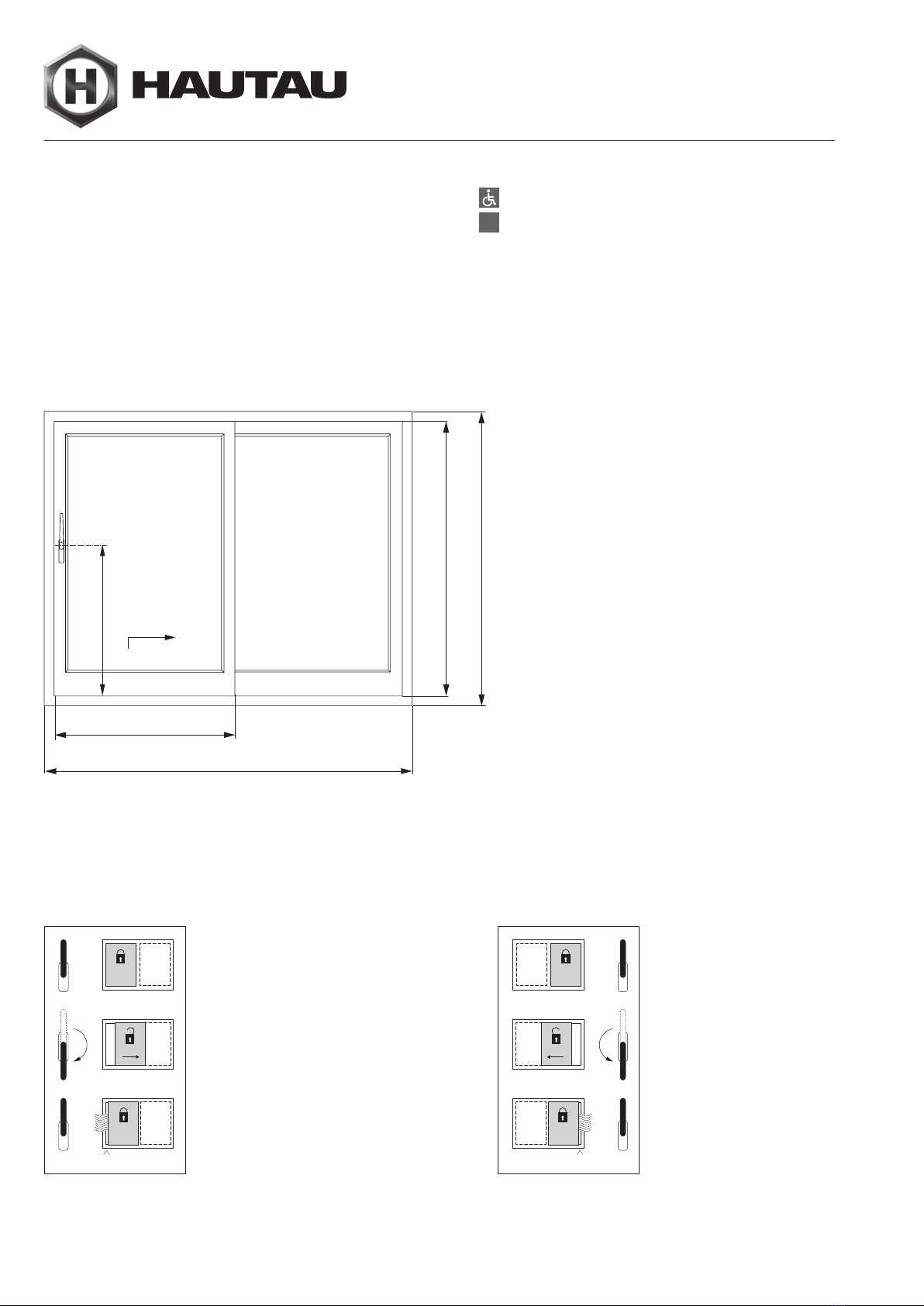
The ATRIUM®HS lift and slide fittings are intended for use only in
stationary buildings. They are used for the horizontal opening and
closing of windows and window doors made from profiles for lift
and slide elements. The lift and slide elements must be installed
perpendicularly, and under no circumstances may they be in a
skewed position.
Mounting requirements
– These mounting instructions and the mounting of the fittings
require specialist knowledge corresponding to successfully
completed training in at least one of the following trades:
construction carpenter, construction metal worker, window and
glass façade installer.
– Assemble the complete fitting only from HAUTAU fitting parts
and the profile system described here. Otherwise, damage may
arise for which we accept no liability.
– Comply with the “Technical specifications and information on
the product and on liability (VHBH)”. Inform the end user about
the contents of the “Technical specifications and information
for end users (VHBE)”.
– Under all circumstances comply with the processing guidelines
of the profile manufacturer.
– Lift and slide elements may be surface-treated only before the
mounting of the fitting parts. Subsequent surface treatment
may have a negative effect on the operability of the fitting
parts. In this case, all guarantee claims against the fitting
manufacturer are nullified.
– The steel fitting parts described in these mounting instructions
have been passivated and sealed as per DIN EN 12329 using
a colourless process. They must not be used in environments
with aggressive and corrosive air components.
– Keep the running track and all rebates free of deposits and
contamination, in order to avoid damage to the fitting and to
ensure optimum functioning. In particular, protect the fitting
from remnants of cement or plaster.
– Do not use acid-curing sealants, as these can result in
corrosion of the fitting parts.
– Avoid directly exposing the fitting to moisture and prevent
acid-containing cleaning agents from coming into contact with
the fitting.
– Keep these mounting instructions in a safe place.
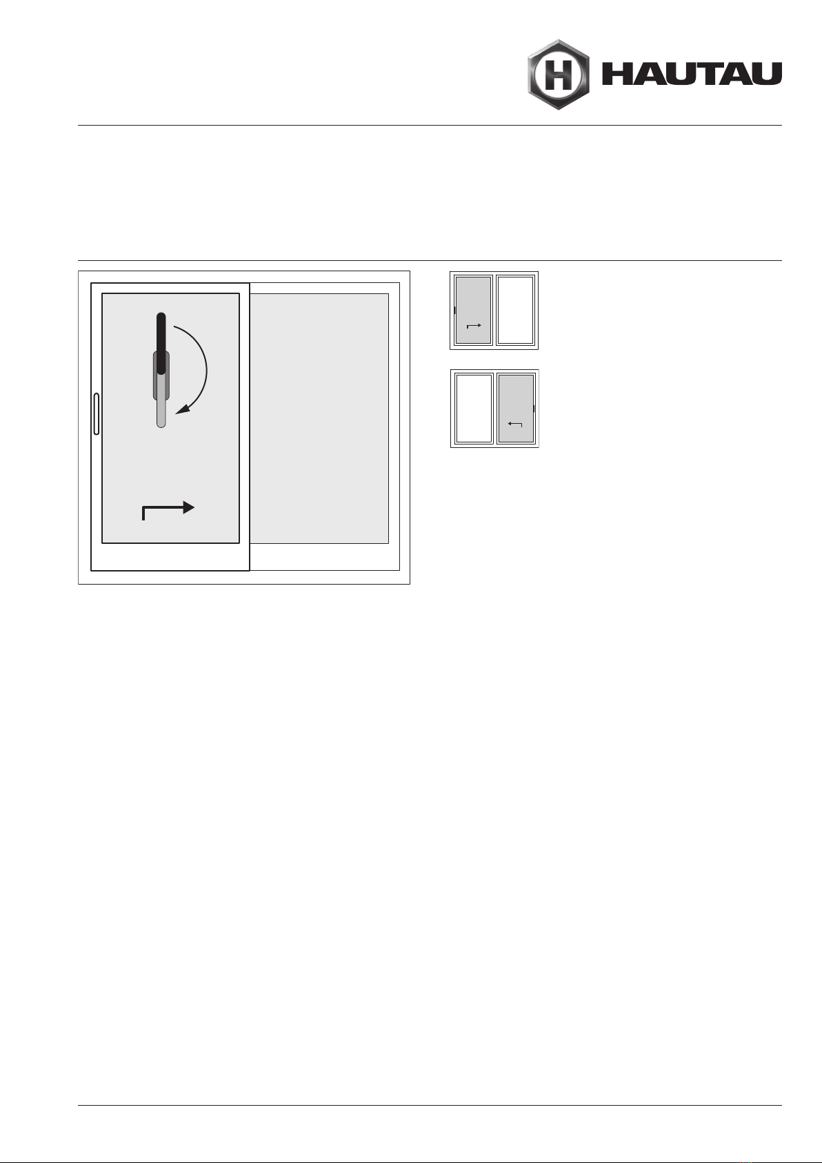
– Apply the operating label (slide direction to DIN left or DIN right)
in a clearly visible position on the lift and slide sash
after it has been installed. The operating label is in the
ATRIUM®HS 330 basic carton.
Allgemeine Informationen | General informations
Bestimmungsgemäßer Gebrauch
Intended use
Bestimmungsgemäßer Gebrauch
Die Hebe-Schiebe-Beschläge ATRIUM®HS sind nur für den
Einsatz in ortsfesten Gebäuden vorgesehen. Sie dienen zum
horizontalen Öffnen und Schließen von Fenstern und Fenstertüren
aus Profilen für Hebe-Schiebe-Elemente. Die Hebe-Schiebe-
Elemente müssen lotrecht, keinesfalls in Schräglage, eingebaut
werden.
Montagevoraussetzungen
– Diese Montageanleitung und der Einbau der Beschläge, setzt
Fachkenntnisse voraus, die einer abgeschlossenen Ausbildung
in mindestens einem der folgenden Berufsbilder entsprechen:
Bautischler/in, Metallbauer/in für Konstruktionstechnik,
Fenster- und Glasfassadenbauer/in.
– Stellen Sie den Gesamtbeschlag nur aus HAUTAU-Beschlag-
teilen und dem hier beschriebenen Profilsystem zusammen.
Andernfalls können Schäden auftreten, für die wir keine
Haftung übernehmen.
– Beachten Sie die “Vorgaben und Hinweise zum Produkt und zur
Haftung (VHBH)”. Informieren Sie den Endanwender über den
Inhalt der “Vorgaben und Hinweise für Endanwender (VHBE)”.
– Folgen Sie auf jeden Fall der Verarbeitungsrichtlinie des Profil-
herstellers.
– Hebe-Schiebe-Elemente dürfen nur vor der Montage der
Beschlagteile oberflächenbehandelt werden. Eine nachträg-
liche Oberflächenbehandlung kann die Funktionstüchtigkeit der
Beschlagteile einschränken. In diesem Fall entfallen jegliche
Gewährleistungansprüche gegenüber dem Beschlaghersteller.
– Die in dieser Montageanleitung beschriebenen Beschlagteile
aus Stahl sind nach DIN EN 12329 farblos passiviert und
versiegelt. Sie dürfen nicht in Umgebungen mit aggressiven
und korrosionsfördernden Luftinhalten verwendet werden.
– Halten Sie die Laufschiene und alle Falze von Ablagerungen
und Verschmutzungen frei, um Beschädigungen am Beschlag
zu vermeiden und die optimale Funktion zu gewährleisten.
Schützen Sie den Beschlag insbesondere vor Zement- oder
Putzrückständen.
– Verwenden Sie keine säurevernetzenden Dichtstoffe, da diese
zur Korrosion der Beschlagteile führen können.
– Vermeiden Sie direkte Nässeeinwirkung auf den Beschlag und
einen Kontakt des Beschlags mit säurehaltigen Reinigungs-
mitteln.
– Bewahren Sie diese Montageanleitung auf.
– Bringen Sie den Bedienungsaufkleber (Schieberichtung DIN links
bzw. DIN rechts) gut sichtbar am eingebauten Hebe-Schiebe-
Flügel an. Der Bedienungsaufkleber befindet sich im Grund-
karton ATRIUM®HS 330.

Seite | Page 4ATRIUM®HS 330 – Rehau Geneo | 500656
~1 cm
~1 cm
~1 cm
~1 cm
FH
RAH
FB
GH
RAB
5
Barrierefrei | barrier-free
5 mm Laufschiene | 5 mm running track
Allgemeine Informationen | General informations
Abkürzungen
Abbreviations
FA Flügelabstand | Sash distance
FB Flügelbreite | Sash width
FFB Festfeldbreite | Fixed glass panel width
FG Flügelgewicht | Sash weight
FH Flügelhöhe Schiebeflügel | Sliding sash height
GH Griffsitz-Höhe | Handle position
LS Laufschiene | Running track
OKFF Oberkante Fertig-Fußboden | Upper edge finished floor
RAB Rahmenaußenbreite | Outer frame width
RAH Rahmenaußenhöhe | Outer frame height
SFB Schiebeflügelbreite | Sliding sash width
exemplarisch: Schema A (andere Schemata entsprechend)
exemplarily: Scheme A (other schemes accordingly)
* HAUTAU-Ausführung Rechts
= DIN EN 12519 Links
(nach links öffnend)
* HAUTAU version Right
= DIN EN 12519 Left
(left-opening)
* HAUTAU-Ausführung Links
= DIN EN 12519 Rechts
(nach rechts öffnend)
* HAUTAU version Left
= DIN EN 12519 Right
(right-opening)
Abkürzungen |Abbreviations
Bedienungen |Operation

Seite | Page 5
ATRIUM®HS 330 – Rehau Geneo | 500656
3300
FH
FB
= bis 30 kg/m²
FH : FB = max. 2,5 : 1
Flügelgewicht
max. 330 kg
= bis 40 kg/m²
= bis 50 kg/m²
= bis 60 kg/m²
3200
3100
3000
2900
2800
2700
2600
2500
2400
2200
2300
2100
2000
1900
1800
1700
1600
1500
1400
1300
1200
720
800
900
1000
1100
1200
1300
1400
1500
1600
1700
1800
1900
2000
2100
2200
2300
2400
2500
2600
2700
2800
2900
3000
3100
3200
3235
1200
1300
1400
1500
1600
1700
1800
1900
2000
2100
2200
2300
2400
2500
2600
2700
2800
2900
3000
3100
3200
3300
= bis 30 kg/m²
= bis 40 kg/m²
= bis 50 kg/m²
= bis 60 kg/m²
FH
720
800
900
1000
1100
1200
1300
1400
1500
1600
1700
1800
1900
2000
2100
2200
2300
2400
2500
2600
2700
2800
2900
3000
3100
3200
3235
FB
1200
1300
1400
1500
1600
1700
1800
1900
2000
2100
2200
2300
2400
2500
2600
2700
2800
2900
3000
3100
3200
3300
FH
1310
1400
1500
1600
1700
1800
1900
2000
2100
2200
2300
2400
2500
2600
2700
2800
2900
3000
3100
3200
3235
FB
= bis 40 kg/m²
= bis 50 kg/m²
= bis 60 kg/m²
Flügelgewicht
max. 440 kg
Allgemeine Informationen | General informations
Anwendungsdiagramm HS 330
Application diagram HS 330
Anwendungsdiagramm HS 330 |Application diagram HS 330
Anwendungsdiagramm HS 440 |Application diagram HS 440

Seite | Page 6ATRIUM®HS 330 – Rehau Geneo | 500656
Verwendung am Bildschirm | Use on screen
Korrekte Darstellung des Layouts
Correct display of the layout
Um den Katalog optimal nutzen zu können, müssen Sie in
ihrem PDF Viewer die Funktionen "Zweiseitenansicht" und
"Deckblatt in Zweiseitenansicht einblenden" (abweichende
Namen in unterschiedlichen Viewer sind möglich) aktivieren.
Entnehmen Sie dem unten stehenden Screenshot wo sie
diese Einstellungen im Adobe Reader 2017 vornehmen
können.
In order to be able to use the catalogue optimally, you
must activate the functions "Two-page view" and "Show
cover page in two-page view" (different names are possible
in different viewers) in your PDF viewer. Please refer to the
screenshot below to see where you can make these settings
in Adobe Reader 2017
Korrekte Darstellung des Layouts
Abb. 1 Adobe Viewer 2017 deutsche Benutzeroberfläche
Fig. 2 Adobe Viewer 2017 english User Interface
Correct display of the layout

Seite | Page 7
ATRIUM®HS 330 – Rehau Geneo | 500656
Verwendung am Bildschirm | Use on screen
Navigation im Dokument
Correct display of the layout
Um eine schnelle Navigation im Dokument zu ermöglichen
sind die Punkte im Inhaltsverzeichnis mit dem jeweiligen
Abschnitten im Dokument verknüpft. Klicken Sie auf den
Abschnitt im Inhaltsverzeichnis um sofort zum entspre-
chenden Abschnitt im Dokument zu springen.
Nutzen Sie das zweite Inhaltsverzeichnis um direkt zu ihrem
gewünschten Abschnitt zu springen.
Ein weiterer Klick auf das Hautau Logo bringt Sie zurück zum
Inhaltsverzeichnis.
Navigation im Dokument
To enable a quick navigation in the document, the items in
the table of contents are linked to the respective sections in
the document. Click on the section in the table of contents to
jump to the corresponding section in the document.
Use the second table of contents to jump directly to your
desired section.
Another click on the Hautau logo will take you back to the
table of contents.
Navigation in the document

Seite | Page 8ATRIUM®HS 330 – Rehau Geneo | 500656
10
*
10
*
In combination with comfort close, in the
upper area of the sash the reinforcement
Profil 1352543 must be installed. Refer to
mounting instructions comfort close.
Important note in case of mounting :
ATRUIM®HS Threshhold
ThermoTop®/ ThermoTop®comfort
ATRUIM®HS comfort close / comfort stop
Wichtiger Hinweis bei Montage : | Important note in case of mounting :
ATRUIM® HS comfort close / comfort stop
In Kombination mit comfort close muss im
oberen Bereich des Flügels die Armierung Profil
1352543 vorhanden sein. Siehe Montage-
anleitung comfort close.
Wichtiger Hinweis bei Montage :
ATRUIM®HS Bodenschwelle
ThermoTop®/ ThermoTop®comfort
Aussteifung: Profil 1352543
Reinforcement: Profil 1352543
comfort close
comfort stop
mit Bodenschwelle ThermoTop®
und Laufschiene 10 mm
with threshold ThermoTop®
and running track 10 mm
*) Armierung Profine Profil V 372 (empfohlen wie abgebildet)
mit Bodenschwelle ThermoTop®comfort
und Laufschiene 10 mm
with threshold ThermoTop®comfort
and running track 10 mm
LS 10 mm
LS 10 mm

Seite | Page 9
ATRIUM®HS 330 – Rehau Geneo | 500656
28.2
28.27
28.29
28.30
28.7
28.9 28.11
28.21
28.13
28.2 Stop for jig for handle
28.7 Jig for external finger grip
28.9 Jig for locking, bottom (for scheme C; F, G, H, L)
28.11 Center punch for locking bolt
28.12 Jig for threshold (top-mounted)
28.21 Jig for threshold-connector
28.27 Jig screw joint espag
28.29 Jig - insert threshold middle post
28.30 Jig kit - Locking bolt
28.31 Milling jig - striker inviso
Mounting tools
(not included in the scope of delivery)
Montagehilfen | Mounting tools
28.2 Anschlag für Bohrlehre Griff
28.7 Fräslehre Griffmuschel
28.9 Bohrlehre Riegelbock (bei Schema C; F, G, H, L)
28.11 Körner Riegelbolzen
28.13 Bohrlehre Bodenschwelle (aufgesetzt)
28.21 Bohrlehre Schwellenverbinder
28.27 Bohrlehre Verschraubung Getriebe
28.29 Bohrlehre Einsätze Schwelle Mittelstoß
28.30 Set Bohrlehre Riegelbolzen
28.31 Fräslehre Schließplatte inviso
Montagehilfen
(nicht im Lieferumfang enthalten)

Seite | Page 10 ATRIUM®HS 330 – Rehau Geneo | 500656
1
21
2
1
2
1
1
FH
RAH
FB
GH
RAB
Schema A
Schema A
Schema D
Schema C
Schema A Schema ASchema C Schema C
B
A A
B
max.
330 kg
1
2
Schema K
11
Schema G-A
1
Schema A Schema C
1
2
Schema C
1
2
Schema C
1
2
Schema C
1
2
A
C
D
F
G
G-A
G-2
G-3
H
K
E
L
1
2
Note: The reference edges for the dimensions are the sash edges without caps.
Schema A | Scheme A
Flügelanordnung
Sash arrangement
FB HS 330 [mm] min.
max.
740
3219,5
FB HS 440 [mm] min.
max.
1450
3219,5
FH [mm] min.
max.
1200
2700
RAB [mm] max. 6500
RAH [mm] min. 1331
2831
FG [kg] max. 330/440
Dornmaß | Backset [mm]
Getriebe | espag
Flügel | sash
37,5
38,7
GH [mm]
Fenster | window FH 1200 … 1800
Tür | door FH 1801 … 2700
403 (comfort: 403)
1003 (comfort: 1003)
HINWEIS: Bezugskanten der Bemaßung sind die Flügelkanten ohne Kappen.
Flügelanordnung
|Sash arrangement
Anwendungsbereich |Range of application
Berechnung der Flügelbreiten |calculation of sashwidth
FB
RAB
FB
63 6315 1595
Flügelbreite (FB)
sash width (FB) ½RAB-30,5
Flügelhöhe (FH)
sash height (FH) RAH-130
Zargenlänge (ZL)
frame length (ZL) RAH - 113

Seite | Page 11
ATRIUM®HS 330 – Rehau Geneo | 500656
Schema A | Scheme A
Befestigungsschrauben
Fastening screws
1) in Abhängigkeit von FB / depending on FB
2) bei Einsatz optionaler Riegelbolzen; bei Schließplatten inviso siehe Abschnitt „Montage der Schließplatten inviso/inviso M“.
when using optional locking bolts; in case of strikers inviso refer to chapter “Mounting of strikers inviso/inviso M“.
für | for Stück
Quantity mm vorbohren
pre-drill
Bauseits
on site
1.1 Laufwagen-Griffseite HS 330
Bogie handle side HS 330 3 + 2 4,8 x 38
+ 3,9 x 45
Ø 4,2 /
Ø 3,5
1.3 Laufwagen
Bogie 24,8 x 38 Ø 4,2
1.8 Tandemlaufwagen HS 440
Tandem bogie HS 440 44,8 x 38 Ø 4,2
3.1 Getriebe HS 300
Espag HS 300 84,8 x 65 Ø 4,2
4.5 Verbindungsschraube (gewindefurchend)
Connecting screw (self-trapping) 1M5 x 12 -
- Führung (bauseits)
Guide (on site) 43,9 x 32 Ø 3,5 ●
6.1 Führungsschiene (bauseits)
Guide track (on site)
1) 4,8 x 45 Linsenkopf-Bohrschraube
Fillister head drilling screw Ø 4,2 ●
4.3/4.4 Riegelbolzen
Locking bolt 4 (8)2) 4,8 x 65 Senkkopf-Bohrschraube
Counter sunk drilling screw Ø 4,2
12.1 Aufbauprofil (bauseits)
Support profile (on site)
1) 3,9 x 32 Senkkopf-Bohrschraube
Counter sunk drilling screw Ø 3,5 ●
9.14 Rahmeneckverbinder (bauseits)
Frame corner connection (on site) 43,9 x 32 Senkkopf-Bohrschraube
Counter sunk drilling screw Ø 3,5 ●
9.18 Dichtblock (bauseits)
Sealing block (on site) 43,9 x 32 Senkkopf-Bohrschraube
Counter sunk drilling screw Ø 3,5 ●
9.12 Endkappen Bodenschwelle
Endcaps threshold 66,3 x 15 Euroschraube Pan-Head
Euro screw Pan-Head -
9.19 Schwellenverschraubung AMO III
Screws threshold AMO III 47,5 x 10² -
-Festfeldverschraubung
fixed sash screws
1) AMO III
7,5 x 110 -●
Befestigungsschrauben |Fastening screws

Seite | Page 12 ATRIUM®HS 330 – Rehau Geneo | 500656
FG max.
330 kg
zusätzlich bei /
additionally for
FG > 330 kg,
max. 440 kg
1.1
1.3
7.1
2.1
4.2
4.2
7.1
7.1
2.3
2.3
4.2
4.2
1.8
1.8
4.2
Laufschiene
Running track 10 mm
4.27.1
7.1
27.4
7.1
7.1
7.1
7.1
4.5
4.4
4.23
4.6
3.13.5
4.3
4.
23
7.4
7.4
7.3
7.3
4.77.2
4.77.2
5.
11
6.1
4.24
4.24
4.15
27.4
9.22
9.22
Beschlagsübersicht |Fittings overview
Schema A | Scheme A
Beschlagsübersicht
Fittings overview
Pos. Beschreibung | Description
Stück
Quantity
1.1 Laufwagen-Griffseite | Bogie handle side 1
1.3 Laufwagen | Bogie 1
1.8 Tandemlaufwagen HS 440 | Tandem bogie HS 440 24)
2.1 Verbindungsstange | Connecting rod 1
2.3 Verbindungsstange Tandemlaufwagen, flach | Connecting rod, flat 24)
3.1 Getriebe | Espag 1
3.5 LM-Griff incl. Schrauben | LM handle incl. screws 1
4.2 Kerbstift / Gewindestifte | Grooved pin / Threaded pin 4(8)2)
4.3 Riegelbolzen | Locking bolt 1 (3)1)
4.4 Riegelbolzen Spaltlüftung | Locking bolt, night vent 1
4.5 Verbindungsschraube (gewindefurchend) |
Connecting screw (self-trapping) 1
4.6 Abdeckstopfen | Cap 1
4.7 Gummipilzpuffer | Sash buffer 2
4.15 Dichtungsplatte Führungsschiene | Sealing plate guide track 1
4.23 Unterlegteil Riegelbolzen | Packers locking bolt 2(4)2)
4.24 U-Führung | U-Guide 2
5.11 Griffmuschel | External finger grip 1
6.1 Führungsschiene | Guiding rail 13)
7.1 Schrauben | Screws s. Tabelle /
refer to table
7.2 Flügelanschlag | Sash buffer 22)
7.3 Unterlegteil Flügelanschlag | Packer sash buffer 22)
7.4 Dübel | Dowel 6
9.22 Laufwagenpositionierung | Bogie positioning device 4
27.4 Aushebelschutz | Anti-lift protection 22)
1) bei Einsatz optionaler Riegelbolzen | in case of using optional locking bolts
2) optional | optional
3) nicht benötigt für montage mit comfort close / comfort stop |
not mandatory for mounting with comfort close / comfort stop
4) für FG>330 Kg | für FG>330 Kg
bei Schließplatten inviso
siehe auch separaten
Abschnitt
in case of strikers
inviso refer to separate
chapter, too

Seite | Page 13
ATRIUM®HS 330 – Rehau Geneo | 500656
8.7
9.14
9.14
8.11
9.18
9.21
9.20
9.5
12.1
12.2
8.3
9.13
9.13
9.17
9.17
8.1
9.10 9.12
9.10
9.12
9.19
9.19
9.21
7x
9.15
9.15
8.11
9.18
9.21
9.20
9.5
12.1
8.3
9.13
9.13
9.17
9.17
9.19
9.19
9.21
8.8
8.12
8.2
9.10 9.12
9.10
9.12
12.2
7x
Schema A | Scheme A
Beschlagsübersicht Bodenschwelle
Fittings overview threshold
ThermoTop®
Pos. Beschreibung | Description
Stück
Quantity ThermoTop®ThermoTop®
comfort
8.1 Grundkörper Bodenschwelle | Base frame threshold 1 x -
8.2 Grundkörper Bodenschwelle comfort | Base frame threshold comfort 1 - x
8.3 Laufschiene 10 mm | Running track 10 mm 1 x x
8.7 Trittschutz | Step protection cover 1 x -
8.8 Trittschutz comfort | Step protection cover comfort 1 - x
8.11 Dichtung Trittschutz | Sealing step protection cover 1 x x
8.12 Keder comfort | Strip comfort 1 - x
9.5 Dichtkissen Mittelstoß | Sealing pad middle post 1 x x
9.10 Dichtung Bodenschwelle (Endkappe) | Sealing threshold (endcap) 2 x x
9.12 Endkappe Bodenschwelle | Endcaps threshold 2 x x
9.13 Euroschraube Pan-Head | Euro screw Pan-Head 4 x x
9.14 Rahmeneckverbinder | Frame corner connection 2 x -
9.15 Rahmeneckverbinder comfort | Frame corner connection comfort 2 - x
9.17 Unterlegteile Bodenschwelle | Packer threshold 4 x x
9.18 Dichtblock | Sealing block 1 x x
9.19 Schrauben Bodenschwelle | Screws threshold s. Tabelle / refer to table 1) x x
9.20 Dichtkissen Rahmeneckverbinder | Sealing pad frame corner connection 1 x x
9.21 Keder LS-Aufnahmenut | Strip LS holding groove 2 x x
12.1 Aufbauprofil | Support profile 1 x x
12.2 Adapterprofil | Adapter profile 7 x x
1) bauseits | on site
ThermoTop®comfort
Beschlagsübersicht Bodenschwelle |Fittings overview threshold

Seite | Page 14 ATRIUM®HS 330 – Rehau Geneo | 500656
A
C
D
F
G
G-A
G-2
G-3
H
K
E
L
1
2
1
21
2
1
2
1
1
FH
RAH
FB
GH
RAB
Schema A
Schema A
Schema D
Schema C
Schema A Schema ASchema C Schema C
B
A A
B
max.
330 kg
1
2
Schema K
11
Schema G-A
1
Schema A Schema C
1
2
Schema C
1
2
Schema C
1
2
Schema C
1
2
Note: The reference edges for the dimensions are the sash edges without caps.
Schema C | Scheme C
Flügelanordnung
Sash arrangement
FB HS 330 [mm] min.
max.
740
3219,5
FB HS 440 [mm] min.
max.
1450
3219,5
FH [mm] min.
max.
1200
2700
RAB [mm] max. 12859
RAH [mm] min. 1331
2831
FG [kg] max. 330/440
Dornmaß | Backset [mm]
Getriebe | espag
Flügel | sash
37,5
38,7
GH [mm]
Fenster | window FH 1200 … 1800
Tür | door FH 1801 … 2700
403 (comfort: 403)
1003 (comfort: 1003)
HINWEIS: Bezugskanten der Bemaßung sind die Flügelkanten ohne Kappen.
Flügelanordnung |Sash arrangement
Anwendungsbereich |Range of application
Berechnung der Flügelbreiten Standard |calculation of sashwidth standard
RAB
63 15
15
95 95
FB
FB FB
FB
6315
Flügelbreite (SFB)
Sash width (SFB) ¼RAB+4,8
Flügelhöhe (FH)
sash hight (FH) RAH - 130
Zargenlänge (ZL)
frame length (ZL) RAH - 113

Seite | Page 15
ATRIUM®HS 330 – Rehau Geneo | 500656
Schema C | Scheme C
Befestigungsschrauben
Fastening screws
für | for Stück
Quantity mm vorbohren
pre-drill
Bauseits
on site
1.1 Laufwagen-Griffseite HS 330
Bogie handle side HS 330 6 + 4 4,8 x 38
+ 3,9 x 45
Ø 4,2 /
Ø 3,5
1.3 Laufwagen
Bogie 44,8 x 38 Ø 4,2
1.8 Tandemlaufwagen HS 440
Tandem bogie HS 440 84,8 x 38 Ø 4,2
3.1 Getriebe HS 300
Espag HS 300 16 4,8 x 65 Ø 4,2
4.5 Verbindungsschraube (gewindefurchend)
Connecting screw (self-trapping) 2M5 x 12 -
- Führung (bauseits)
Guide (on site) 44,8 x 45 Ø 4,2 ●
6.1 Führungsschiene (bauseits)
Guide track (on site)
1) 3,9 x 32 Linsenkopf-Bohrschraube
Fillister head drilling screw Ø 3,5 ●
4.3/4.4 Riegelbolzen
Locking bolt 4 (8)2) M5 x 35 Senkkopf-Bohrschraube
Counter sunk drilling screw Ø 4,5
12.1 Aufbauprofil (bauseits)
Support profile (on site)
1) 3,9 x 32 Senkkopf-Bohrschraube
Counter sunk drilling screw Ø 3,5 ●
9.14/
9.15
Rahmeneckverbinder (bauseits)
Frame corner connection (on site) 43,9 x 32 Senkkopf-Bohrschraube
Counter sunk drilling screw Ø 3,5 ●
9.18 Dichtblock (bauseits)
Sealing block (on site) 83,9 x 32 Senkkopf-Bohrschraube
Counter sunk drilling screw Ø 3,5 ●
9.12 Endkappen Bodenschwelle
Endcaps threshold 66,3 x 15 Euroschraube Pan-Head
Euro screw Pan-Head -
9.19 Schwellenverschraubung AMO III
Screws threshold AMO III 47,5 x 10² -
-Festfeldverschraubung
fixed sash screws
1) AMO III
7,5 x 110 -●
1) in Abhängigkeit von FB / depending on FB
2) bei Einsatz optionaler Riegelbolzen; bei Schließplatten inviso siehe Abschnitt „Montage der Schließplatten inviso/inviso M“.
when using optional locking bolts; in case of strikers inviso refer to chapter “Mounting of strikers inviso/inviso M“.
Befestigungsschrauben |Fastening screws

Seite | Page 16 ATRIUM®HS 330 – Rehau Geneo | 500656
20.2
27.4
7.1
7.1
7.1
7.1
4.5
4.4
4.23
4.6
3.13.5
4.3
4.
23
7.4
7.4
7.3
7.3
4.77.2
4.77.2
5.
11
6.1
4.24
4.24
4.15
27.4
FG max.
330 kg
zusätzlich bei /
additionally for
FG > 330 kg,
max. 440 kg
1.1
1.3
7.1
2.1
4.2
4.2
7.1
7.1
2.3
2.3
4.2
4.2
1.8
1.8
4.2
Laufschiene
Running track 10 mm
4.27.1
7.1
9.22
9.22
Schema C | Scheme C
Beschlagsübersicht
Fittings overview
Pos. Beschreibung | Description
Stück
Quantity
1.1 Laufwagen-Griffseite | Bogie handle side 2
1.3 Laufwagen | Bogie 2
1.8 Tandemlaufwagen HS 440 | Tandem bogie HS 440 44)
2.1 Verbindungsstange | Connecting rod 2
2.3 Verbindungsstange Tandemlaufwagen, flach | Connecting rod, flat 44)
3.1 Getriebe | Espag 2
3.5 LM-Griff incl. Schrauben | LM handle incl. screws 2
4.2 Kerbstift / Gewindestifte | Grooved pin / Threaded pin 8(16)2)
4.3 Riegelbolzen | Locking bolt 1 (3)1)
4.4 Riegelbolzen Spaltlüftung | Locking bolt, night vent 1
4.5 Verbindungsschraube (gewindefurchend) /
Connecting screw (self-trapping) 2
4.6 Abdeckstopfen | Cap 2
4.7 Gummipilzpuffer | Sash buffer 4
4.15 Dichtungsplatte Führungsschiene | Sealing plate guide track 2
4.23 Unterlegteil Riegelbolzen | Packers locking bolt 2(4)2)
4.24 U-Führung | U-Guide 4
5.11 Griffmuschel | External finger grip 2
6.1 Führungsschiene 1
7.1 Schrauben | Screws s. Tabelle /
refer to table
7.2 Flügelanschlag | Sash buffer 42)
7.3 Unterlegteil Flügelanschlag | Packer sash buffer 4
7.4 Dübel | Dowel 8(12)2)
9.22 Laufwagenpositionierung | Bogie positioning device 8
20.2 Riegelbock | locking bottom 1
27.4 Aushebelschutz | Anti-lift protection 4
1) bei Einsatz optionaler Riegelbolzen | in case of using optional locking bolts
2) optional | optional
3) nicht benötigt für montage mit comfort close / comfort stop |
not mandatory for mounting with comfort close / comfort stop
4) für FG>330 Kg | für FG>330 Kg
bei Schließplatten inviso
siehe auch separaten
Abschnitt
in case of strikers
inviso refer to separate
chapter, too
Beschlagsübersicht |Fittings overview

Seite | Page 17
ATRIUM®HS 330 – Rehau Geneo | 500656
9.14
9.21
9.13
9.13
9.17
9.17
9.19
9.19
9.14
9.18
R
9.5R
9.20
9.5
L
12.1
9.18
L
9.20
8.3
9.21 9.10 9.12
9.10
9.12
8.7
8.11
8.1
12.2
7x
12.2
7x
8.2
8.11
9.21
9.13
9.13
9.17
9.17
9.19
9.19
9.10
9.12
9.10 9.12
9.15
9.18
R
9.5R
9.20
9.5
L
12.1
9.18
L
9.20
8.12
8.8
8.3
9.21
9.15
12.2
7x
12.2
7x
Schema C | Scheme C
Beschlagsübersicht Bodenschwelle
Fittings overview threshold
ThermoTop®
ThermoTop®comfort
Pos. Beschreibung | Description
Stück
Quantity ThermoTop®ThermoTop®
comfort
8.1 Grundkörper Bodenschwelle | Base frame threshold 1 x -
8.2 Grundkörper Bodenschwelle comfort | Base frame threshold comfort 1 - x
8.3 Laufschiene 10 mm | Running track 10 mm 1 x x
8.7 Trittschutz | Step protection cover 1 x -
8.8 Trittschutz comfort | Step protection cover comfort 1 - x
8.11 Dichtung Trittschutz | Sealing step protection cover 1 x x
8.12 Keder comfort | Strip comfort 1 - x
9.5L Dichtkissen Mittelstoß | Sealing pad middle post 1 x x
9.5R Dichtkissen Mittelstoß | Sealing pad middle post 1 x x
9.10 Dichtung Bodenschwelle (Endkappe) | Sealing threshold (endcap) 2 x x
9.12 Endkappe Bodenschwelle | Endcaps threshold 2 x x
9.13 Euroschraube Pan-Head | Euro screw Pan-Head 6 x x
9.14 Rahmeneckverbinder | Frame corner connection 2 x -
9.15 Rahmeneckverbinder comfort | Frame corner connection comfort 2 - x
9.17 Unterlegteile Bodenschwelle | Packer threshold 4 x x
9.18L Dichtblock | Sealing block 1 1) x x
9.18R Dichtblock | Sealing block 1 1) x x
9.19 Schrauben Bodenschwelle | Screws threshold s. Tabelle / refer to table 1) x x
9.20 Dichtkissen Rahmeneckverbinder | Sealing pad frame corner connection 2 x x
9.21 Keder LS-Aufnahmenut | Strip LS holding groove 2 x x
12.1 Aufbauprofil | Support profile 2 x x
12.2 Adapterprofil | Adapter profile 14 x x
1) bauseits | on site
Beschlagsübersicht Bodenschwelle |Fittings overview threshold

Seite | Page 18 ATRIUM®HS 330 – Rehau Geneo | 500656
A
C
D
F
G
G-A
G-2
G-3
H
K
E
L
1
2
1
21
2
1
2
1
1
FH
RAH
FB
GH
RAB
Schema A
Schema A
Schema D
Schema C
Schema A Schema ASchema C Schema C
B
A
A
B
max.
330 kg
1
2
Schema K
11
Schema G-A
1
Schema A Schema C
1
2
Schema C
1
2
Schema C
1
2
Schema C
1
2
Note: The reference edges for the dimensions are the sash edges without caps.
Schema K | Scheme K
Flügelanordnung
Sash arrangement
FB HS 330 [mm] min.
max.
740
3219,5
FB HS 440 [mm] min.
max.
1450
3219,5
FH [mm] min.
max.
1200
2700
RAB [mm] max. 12837
RAH [mm] min. 1332
2832
FG [kg] max. 330/440
Dornmaß | Backset [mm]
Getriebe | espag
Flügel | sash
37,5
38,5
GH [mm]
Fenster | window FH 1200 … 1800
Tür | door FH 1801 … 2700
403 (comfort: 403)
1003 (comfort: 1003)
HINWEIS: Bezugskanten der Bemaßung sind die Flügelkanten ohne Kappen.
Flügelanordnung |Sash arrangement
Berechnung der Flügelbreiten |calculation of sashwidth
Anwendungsbereich |Range of application
RAB
SFB
FFB
SFB
63 6315 15
9595
Schiebeflügelbreite (SFB)
slide sash width (SFB) 2
(RAB - FFB + 34)
Festflügelbreite (FFB)
fixed sash width (FFB) RAB-2xSF+34
Flügelhöhe (FH)
sash hight (FH) RAH - 130
Zargenlänge (ZL)
frame length (ZL) RAH - 113

Seite | Page 19
ATRIUM®HS 330 – Rehau Geneo | 500656
Schema K | Scheme K
Befestigungsschrauben
Fastening screws
für | for Stück
Quantity mm vorbohren
pre-drill
Bauseits
on site
1.1 Laufwagen-Griffseite HS 330
Bogie handle side HS 330 6 + 4 4,8 x 38
+ 3,9 x 45
Ø 4,2 /
Ø 3,5
1.3 Laufwagen
Bogie 44,8 x 38 Ø 4,2
1.8 Tandemlaufwagen HS 440
Tandem bogie HS 440 84,8 x 38 Ø 4,2
3.1 Getriebe HS 300
Espag HS 300 16 4,8 x 65 Ø 4,2
4.5 Verbindungsschraube (gewindefurchend)
Connecting screw (self-trapping) 2M5 x 12 -
- Führung (bauseits)
Guide (on site) 43,9 x 32 Ø 3,5 ●
6.1 Führungsschiene (bauseits)
Guide track (on site)
1) 4,8 x 45 Linsenkopf-Bohrschraube
Fillister head drilling screw Ø 4,2 ●
4.3/4.4 Riegelbolzen
Locking bolt 8 (16)2) 4,8 x 65 Senkkopf-Bohrschraube
Counter sunk drilling screw Ø 4,2
12.1 Aufbauprofil (bauseits)
Support profile (on site)
1) 3,9 x 32 Senkkopf-Bohrschraube
Counter sunk drilling screw Ø 3,5 ●
9.14/
9.15
Rahmeneckverbinder (bauseits)
Frame corner connection (on site) 43,9 x 32 Senkkopf-Bohrschraube
Counter sunk drilling screw Ø 3,5 ●
9.18 Dichtblock (bauseits)
Sealing block (on site) 83,9 x 32 Senkkopf-Bohrschraube
Counter sunk drilling screw Ø 3,5 ●
9.12 Endkappen Bodenschwelle
Endcaps threshold 66,3 x 15 Euroschraube Pan-Head
Euro screw Pan-Head -
9.19 Schwellenverschraubung AMO III
Screws threshold AMO III 47,5 x 10² -
-Festfeldverschraubung
fixed sash screws
1) AMO III
7,5 x 110 -●
1) in Abhängigkeit von FB / depending on FB
2) bei Einsatz optionaler Riegelbolzen; bei Schließplatten inviso siehe Abschnitt „Montage der Schließplatten inviso/inviso M“.
when using optional locking bolts; in case of strikers inviso refer to chapter “Mounting of strikers inviso/inviso M“.
Befestigungsschrauben |Fastening screws

Seite | Page 20 ATRIUM®HS 330 – Rehau Geneo | 500656
27.4
7.1
7.1
7.1
7.1
4.5
4.4
4.23
4.6
3.13.5
4.3
4.
23
7.4
7.4
7.3
7.3
4.77.2
4.77.2
5.
11
6.1
4.24
4.24
4.15
27.4
FG max.
330 kg
zusätzlich bei /
additionally for
FG > 330 kg,
max. 440 kg
1.1
1.3
7.1
2.1
4.2
4.2
7.1
7.1
2.3
2.3
4.2
4.2
1.8
1.8
4.2
Laufschiene
Running track 10 mm
4.27.1
7.1
9.22
9.22
Beschlagsübersicht |Fittings overview
Schema K | Scheme K
Beschlagsübersicht
Fittings overview
Pos. Beschreibung | Description
Stück
Quantity
1.1 Laufwagen-Griffseite | Bogie handle side 2
1.3 Laufwagen | Bogie 2
1.8 Tandemlaufwagen HS 440 | Tandem bogie HS 440 4
2.1 Verbindungsstange | Connecting rod 2
2.3 Verbindungsstange Tandemlaufwagen, flach | Connecting rod, flat 4
3.1 Getriebe | Espag 2
3.5 LM-Griff incl. Schrauben | LM handle incl. screws 2
4.2 Kerbstift / Gewindestifte | Grooved pin / Threaded pin 8(16)2)
4.3 Riegelbolzen | Locking bolt 2 (6)1)
4.4 Riegelbolzen Spaltlüftung | Locking bolt, night vent 2
4.5 Verbindungsschraube (gewindefurchend) /
Connecting screw (self-trapping) 2
4.6 Abdeckstopfen | Cap 2
4.7 Gummipilzpuffer | Sash buffer 4
4.23 Unterlegteil Riegelbolzen | Packer locking bolt 4 (8)1)
4.24 U-Führung | U-guide 4
5.11 Griffmuschel | External finger grip 2
6.1 Führungsschiene | Guide track 1
7.1 Schrauben | Screws s. Tabelle / refer
to table
7.2 Flügelanschlag | Sash buffer 42)
7.3 Unterlegteil Flügelanschlag | Packer sash buffer 42)
7.4 Dübel | Dowel 8(12)2)
9.22 Laufwagenpositionierung | Bogie positioning device 8
27.4 Aushebelschutz | Anti-lift protection 2
1) bei Einsatz optionaler Riegelbolzen | in case of using optional locking bolts
2) optional | optional
3) nicht benötigt für montage mit comfort close / comfort stop |
not mandatory for mounting with comfort close / comfort stop
4) für FG>330 Kg | für FG>330 Kg
bei Schließplatten
inviso siehe auch
separaten Abschnitt
in case of strikers
inviso refer to
separate chapter, too
Other manuals for ATRIUM HS
3
This manual suits for next models
8
Table of contents
Other HAUTAU Household Hardware manuals