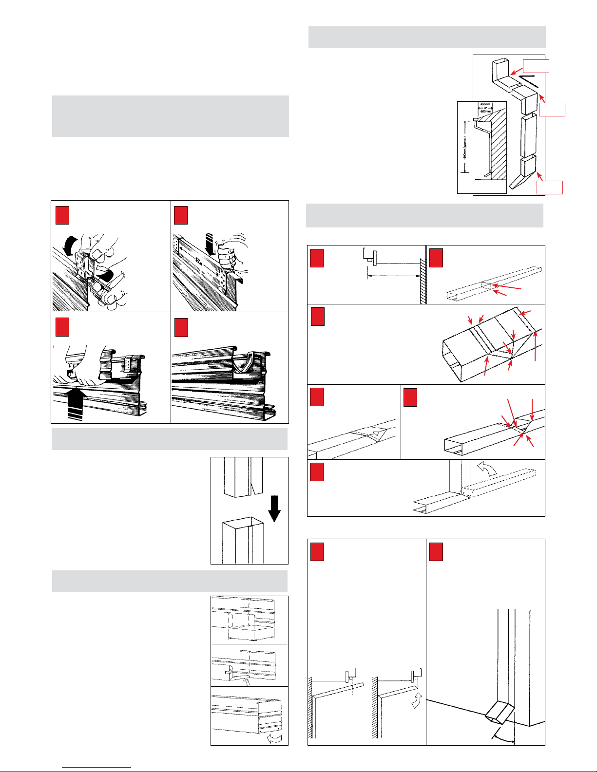
Stratco Gutters User manual

BEFORE YOU START COMPONENTS & ACCESSORIES
TOOLS REQUIRED INSTALLATION
GUTTER STYLES REMINDERS
When your material has arrived on site, check each piece
against the cartnote supplied. Carefully read this leaflet
to ensure that you are familiar with all the steps involved.
Ensure you have adequate tools for the job.
HACKSAW
TAPE MEASURE
TIN SNIPS
RIVET GUN
DRILL / DRILL BITS
SPIRIT LEVEL
STRING LINE
Stratco has designed an extensive choice of gutter styles, from
the more traditional colonial styles to today’s modern
contemporary designs. Most of Stratco’s gutters have the
revolutionary suspension rib. This enables the gutter if used
with either Clickfast®, or Clickform™ steel fascia, to be fixed
with the Stratco Suspension Clip, the system which has proudly
received an Australian Classic Design Award. When using timber
fascia the suspension rib can be used with timber fix clips.
Stratco Gutters and Downpipes are both fashionable and functional accessories, that enhance the look of your
home and minimise the risk from water damage. Stratco offer a range of quality gutter and downpipe products
and all the advice and tools you need to do a competent job for yourself. Do not underestimate the damage poor
gutters and downpipes cause, take these handy tips and replace them now. For information on installing High
Fronted Gutters please refer to the Stratco ‘High Fronted Gutters Information Guide’ on the Stratco website.
HACKING KNIFE
HAMMER
SILICONE
WALKING PLANKS
RIVETS 1/8”X1/8”
30mm GALV. CLOUTS
LADDERS & SCAFFOLD
Note: Many gutters are available slotted to prevent overflow
water from entering the eaves. Check with your local Stratco
office to confirm if this is available in your gutter profile.
VFC AND VC SQUARE
FASCIA GUTTER
125D (QUAD) GUTTER
150 HALF ROUND
GUTTER
OG GUTTER
CLICKFORM EAVES
GUTTER
150 SMOOTHLINE
GUTTER

ACCESSORIES
PRE-INSTALLATION
MITRES
INTERNAL/EXTERNAL
GUTTER STRAPS:
INTERNAL / EXTERNAL
MITRE GUSSETS
STOP ENDS
P CLIPS
GUTTER OUTLETS
ELBOWS &
SHOES
SUSPENSION CLIPS
DOWNPIPES
MEASURING
Measure length of fascia,
allowing enough for mitres
and any joints that may
be required. Generally,
external corners will
require at least twice the width of the gutter to be sacrificed making
the mitre, but internal corners require no extra material. Joins should
overlap approx 100mm. If installing pre-made stop ends no extra
length is required, but “return” stop ends require the width of the
gutter to be added for each stop end.
DETERMINE GUTTER SUPPORT
There are 4 basic methods of supporting a gutter.
A: External brackets.
B: Internal straps and P clips.
C: Internal straps and scotia.
D: Suspension clips and internal straps.
DETERMINE GUTTER FALLS
1: Using a string line, nail one end to
the fascia, running string line from
corner to corner, making sure the
string line is taut.
2: The fall of the gutter should be
calculated (correct fall is 1:500).
Check the fall with a spirit level.
The fall must run towards the
gutter outlet.
EXTERNAL BRACKETS
Nail External brackets at 1.2 metre centres,
following string line. Once all brackets
have been installed, place gutters into
external brackets. Bend tag over bead to
hold in place
P - CLIPS
Install P-clips if required using the same
method as external brackets. Once
P-clips have been installed, sit gutters
onto P-clip lip then bend small tag of
P-clip over back of gutter to hold the
gutter into position.
INTERNAL STRAPS
Install internal straps at 1.2 metre
centres to hold face of gutter into
position. Install pre-made mitres into
corners. Internal straps can also be used
in conjunction with gutter suspended on
timber scotia nailed to a timber fascia.
SUSPENSION CLIPS
This can be used on steel & timber
Fascia with Internal Straps. No string line
is required. For timber fascia nail your
timber suspension clip into place by
placing a clout into the allocated hole in
the top of the clip and driving the clout
into the top of the timber fascia, holding
the clip into position. Clips are to be
placed at maximum of 1.2m centres.
Steel fascia suspension clips are rolled
over the top of steel fascia and placed
into position at 1.2m centres. (See
section on steel fascia).
INSTALLATION OF GUTTER
INSTALLATION OF BRACKETS
Gutter and
external
bracket
Without
scotia,
using
P-clips and
internal
strap
Without
scotia,
using
timber
suspension
and internal
strap
With
scotia,
using
internal
strap
Metal
suspension
clip and
internal
strap.
1: Ensure all gutter outlets and stop ends are fitted at the correct
locations prior to installation of the gutter.
2: Place gutter on P-clips or scotia already
installed and hold into place by driving
a galvanised nail into the fascia just
above the back of the gutter. Bend the
nail down to hold the gutter but allow
expansion and contraction.
3: To install the next length of gutter,
determine the fall of the gutter. Joins
should always be overlapped to allow
water to flow “over” the joint instead of
“into” the joint. Open the bead of the
“outside” gutter with a pair of pliers, and
close up the bead of the “inside” gutter.
4: Slide the upstream gutter (inside) into
the downstream gutter (outside) allowing
a 100mm lap. Rivet and silicone the two
gutters together, ensuring that all metal
filings (swarf) are first cleaned from the
gutter. Silicone should be smoothed to
ensure that the passage
of water is not impeded.
Rivet and silicone stop ends
DOWNPIPE
OFFSETS
PRE-ASSEMBLE MITRES, STOP ENDS AND OUTLETS.
Determine method of supporting and strengthening gutter on the
fascia. Gutter support can include external brackets, or internal
straps used in conjunction with either P-clips, timber scotia or
suspension clips.
1: Cut required length with hacksaw and tinsnips.
2: Fit stop ends where required.
3: Cut holes (outlets) for gutters with a hacking knife, and rivet outlet
into position.
4: Cut mitres where needed. Pre-made mitres are available. See the
section on making mitres if you wish to make your own.
5: Remove all swarf and debris from inside of gutters. If gutters
are pre-coloured steel remove plastic from outside of gutters prior
to installation.
6: Seal internally all stop ends, gutter outlets and mitres with
silicone sealant.
7: Make downpipe offsets. Pre-made downpipe offsets are available,
however see section on making offsets if you wish to make your own.
2:
3:
4:
100mm

CLIP SPACING
Knock suspension clip
down with fist. Place at 1.2
metre
intervals.
1: Measure the distance between the bottom
of the gutter to the ground level (leave
enough to fit a shoe or PVC fitting).
2: Slide the small end of one downpipe
(marked by a cut V or dot one end) into the
big end of the other. Rivet the downpipe at
the back as not to show the rivet head, then
use a hacksaw to cut to the desired length.
3: Fit the downpipe to the existing outlet
using rivets, then using downpipe straps,
fix against wall or post using screws or
masonry nails.
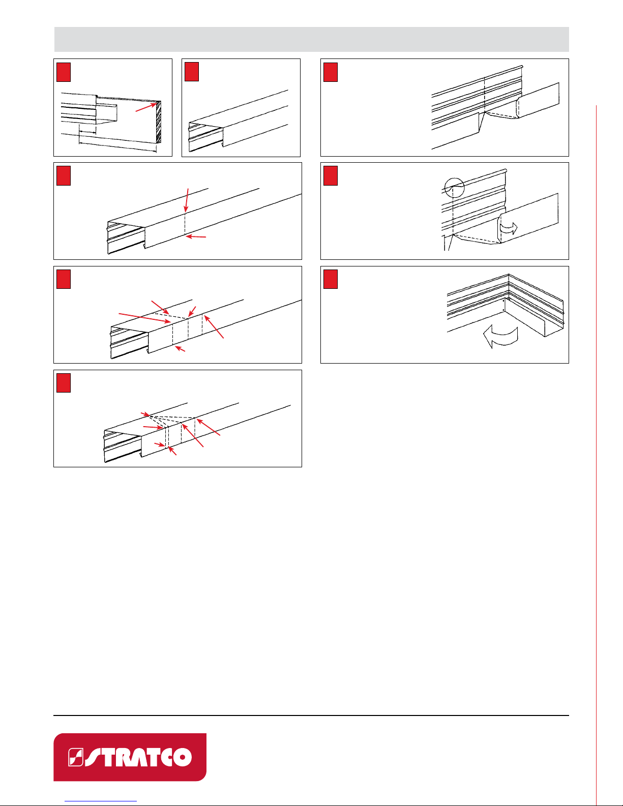
1: Determine if the end is to be left or right.
2: Mark a line completely around the outside
of the gutter at a distance from the end,
equal to the width of the gutter.
3: Mark a tag-line paralell to the first
approximately 10mm toward the end of
the gutter, across the back and the base of
the gutter.
4: Cut the back and the base from the gutter
leaving the 10mm tags in place. Fold these
up at 90 degrees.
5: Cut a 45˚notch in the bead of the gutter
at the marked line, and fold the face of the
gutter to form the end.
6: Rivet and silicone.
FIXING DOWNPIPE TO GUTTER
MAKING ‘RETURN’ STOP ENDS
When installing downpipes, sometimes
the eaves overhang will require the use of
a downpipe offset. There are two ways of
producing a downpipe offset.
1: Stratco produce a complete downpipe
offset, which is suitable for your
nominated eaves dimension. This has a
slip joint to make it adjustable for small
variances in eaves sizes, which may vary
on your home.
2: Elbows and shoes can also be pre-made
and then riveted onto your downpipe
length producing your own downpipe
offset. Alternately, one piece downpipe
offsets can be made on the site.
DOWNPIPE OFFSETS
INSTALLATION OF GUTTERS
USING SUSPENSION CLIPS
Gutter is pulled upwards until the suspension clip engages into the
suspension rib of gutter. Place internal gutter strap into position.
The fall of the gutter is obtained by a series of teeth placed on the
suspension clip. The highest end of the gutter should be in the top
tooth. The lowest end in the second to bottom (minimum 1: 500
fall required).
ROLL IN CLIPS.
Push suspension clip up
from rear and into the
vertical
position as
shown.
12
INSTALL GUTTER
Pull gutter upwards until
suspension clip engages.
3FIX INTERNAL STRAPS
Roll gutter strap into bead
& press over top of fascia.
4
Using a hacksaw, cut
a small section out
inside the lines, big
enough to gain access
for your tinsnips.
Steps 1-3
Steps 4-5
Small
end
Large
end
Steps 5-6
4
Using snips, cut along
the “inside” lines of
C1-A1-A2-B2 leaving the
10mm tag for the lap
joint intact. Complete the cut
across the face of the
downpipe and
repeat on the
other side.
5
Bend the downpipe along the undercut
side to allow the big end of the
downpipe to fit inside the lower part
of the offset.
Rivet and silicone.
6
Place completed “Lower Offset”
joint against the wall with the
large end of downpipe towards the
gutter outlet.
• Using a plumb line mark from the
outside of the gutter outlet, completly
down the side of downpipe. This point
becomes the centre point of the cut of
the upper offset joint, to be marked
out. Cut and seal as per steps 3 to 6
above. It is important to note that for the
“Upper Offset” the opposite face of the
downpipe is used so the seam is cut.
• Before riveting the top of the offset
joint completely, check to make sure the
top of the offset joint is parallel to the
bottom part of the downpipe offset.
1
GUTTER INSTALLATION CONTINUED
5: Fit pre-made gutter mitres as required.
6: Roll internal straps into the bead of the gutter if being used and
fasten to the top of the fascia. Use the gutter strap to ensure the
bead remains parallel to the fascia.
7: Fit downpipe, downpipe accessories and straps.
CREATING THE “LOWER OFFSET” JOINT.
CREATING THE “UPPER
OFFSET” JOINT
Using a second length of down-
pipe, measure in from the “small”
end of the downpipe, the length
required to bring the downpipe
into the stormwater pipe, allowing for a
slip joint, and mark this distance com-
pletely around the pipe using a square.
• To create a 45 degree angle, mark a
distance equal to half the width of
the downpipe on
either side of this cen-
tre line on the face of
the downpipe.
• Mark out, cut and
seal as per steps
3 - 6 above.
• Slide the upper and
lower offsets together
to form the final
finished offset.
1
CREATING THE “SHOE”
Place this measurement along the
downpipe starting from the “Big End”,
and mark this completely
around the pipe at point.
A.
45˚
Measure
from the wall
to the outside
of the gutter outlet.
Add to this measurement 100mm plus
twice the width of the downpipe.
1
Measure the width of the downpipe.
Mark this width on the face of the
downpipe either side of the centre line
to points Band C. To achieve an angle
of approx. 100˚(which allows for downpipe
fall) come in 10mm both sides to B1 and C1.
On the big end side of the centre line come in
a further 10mm for a lap to point B2.
Join points B-A1, C1-A1, and draw a line
parallell to B-A1 to intersect A-A1 at A2.
3
A1
B1
B1
B2
B2
A
A
C1
C1
B
A1
A1
C
A2
A2
100˚
STRATCO PRE-
MADE OFFSET
Lower off-
set joint
Upper off-
set joint
Downpipe
shoe
2
MAKING A DOWNPIPE OFFSET

TO MAKE A GUTTER MITRE
Measure fascia from the corner
of the fascia to existing gutter
allowing 100mm for gutter lap.
1
Place length of gutter upside
down on the ground so that the
base of the gutter is facing you.
2
Mark where the fascia corner will
occur (point A) on the back of
gutter, and using a 90˚ square
and pencil, draw a line across the
outside of the back of gutter.
3
On the back of the gutter place a further 2 marks, each equal to the width of
the gutter (at points Band C) to extend beyond the fascia corner. The central
mark Bshould be extended completely around the outside of the gutter using
the 90˚ square and pencil.
4
On the base of gutter, draw a line to connect the continuous line from B1 to
both Aand C. Mark a line 10mm away from, but parallel to A-B1, and extend
this across the back of the gutter. This will produce a “lap” when the gutter
mitre is formed. This parallel line should
also extend up the back
of the gutter to A1.
5
Using tinsnips, cut along the
line on one side and on the
other side, cut on the parallel
line which is 10mm in from the
original line drawn connecting
A-B1. You will cut out the
complete V marked into the gutter.
In addition, remove excess
material at Aand B1 to allow the
outside of the gutter to fold easily,
and the tags to overlap.
6
For a square gutter cut a 45˚
notch into the bead of the
gutter using a hacksaw and
tin snips at B1 directly in line with
the point of the V on the base of the
gutter. For gutters with an external
bead, such as quad (D) or OG, a
single hacksaw cut is used to cut the
bead. A mitre gusset must then be
attached to complete the bead line.
7
Fold the gutter around until the back
sections touch each other. Fold tag
inside the back gutter. Rivet and
silicone. You have produced an external
gutter mitre. To produce an internal
gutter mitre, reverse your V line marks on
the gutter so that point B1 is exchanged
for point Band the face of the gutter is
cut out not the back. Then follow the
above steps. With some gutters a mitre
gusset will be required to cover any gap in
the gutter bead.
8
B1
B1
A
A
A1
A
B
B
A1
A1
A
C
10mm
C
COMPLY WITH REGULATIONS
All building work must be carried out in accordance with the Building Code of Australia (BCA).
This code refers to various Australian Standards, which provides acceptable standards of
product manufacture and building practice. These include:
• AS/NZ 3500.3 Plumbing and Drainage, Stormwater Drainage
• AS/NZS 3500.5 National Plumbing and Drainage, Domestic Installations
Prospective users of Stratco materials should first ensure that they understand these
requirements and any other state or territory specific regulations that may apply. In some
states of Australia (eg. NSW and Victoria) work involving the installation of roofing, rainwater
goods and drainage may need to be installed by a suitably qualified tradesperson, and comply
with statutory warranties. (Refer www.deus.nsw.gov.au/water/plumbing.asp)
Care should also be taken in the design and installation of roof drainage systems given the
wide range of factors such as rainfall intensity, gutter capacity and selection, number and
placement of downpipes and sumps. Care should also be taken to select the most suitable
gutter style. Gutters that have a front higher than the back are popular to hide the exposed
ends of roofing, but unless manufactured with optional slots or fixed with the bead lower
than the top of the fascia may contravene building regulations. Other fixing options can be
used to eliminate overflow from the back of a gutter into a building. These include additional
overflow weirs placed either in the gutter or stop end, rainheads with overflow weirs, custom
back flashings, leaving a gap between the fascia and gutter back, or other proprietary systems
or trade solutions.
Up to date information about Stratco products, spans, installation requirements and technical
advice can be found on our website at www.stratco.com.au and it is advisable to obtain current
information prior to ordering any materials. If additional information is required contact the
Stratco office in your state.
REMEMBER TO
• Waterproof each rivet with silicone sealant applied on the “weather” side.
• The minimum fall of guttering to the downpipe end is 1 in 500 (or 12mm every 6m).
CONTACT
1300 165 165
www.stratco.com.au All brands and logos/images accompanied by ® or ™ are trade
marks of Stratco (Australia) Pty Limited.
This manual suits for next models
1
Table of contents
Other Stratco Household Hardware manuals