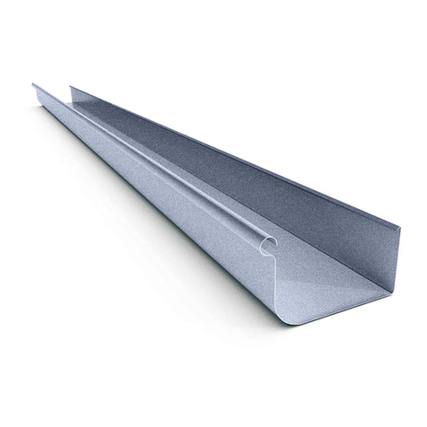
Siegenia Snapper ALU User manual

Pos. Qty. Description Material no. Material no.
1Snapper LM (G1 min. 420) 1 817957 50 219744
11snapper LM
21countersunk screw B4,2 x 22
31sleeve
1Snapper LM - DS 1 817940 50 219737
41snapper LM
51run up block
Installation Instruction
H48.ZUBHLS010en
H48.ZUBHLS010en/0
2
1
For accessories to Siegenia ALU Fittings the information about LM euro-
groove on aluminium profiles for windows and window-doors applies.
In addition, information from the system producers must be observed.
345
Accessories ALU
Snapper ALU
Snapper ALU - DS
H48.ZUBHLS010en
Page 1
2014-07
20
21 +1
22
15
10 bis 14
LM euro-groove
Technical specifications and colours are subject to change

SIEGENIA-AUBI KG
Industriestraße 1-3 D-57234 Wilnsdorf, Germany
Telefon +49 271 39 31-0 - Fax +49 271 39 31-3 33
bei KPS (G1 min. 450)
Important information
- Please observe our product information “Tilt & turn hardware for windows and patio doors”.
- For the hardware described in these assembly instructions the information on applicable size ranges in the specific ALU-assembly
instructions must be observed.
- The hardware components specified in these assembly instructions are made from rust-resistant material.
- Assemble window hardware only from SIEGENIA-components. We are not responsible for damages resulting from failure to
follow this instruction.
- Install all hardware components properly following the assembly instructions on this page.
- Never use acetic or acid cure sealants as they can cause the hardware components to corrode.
- Window and door elements may only be surface treated before installing the hardware components. Treating these surfaces
at a later stage can reduce the functional capacity of the hardware components.
In such cases we are not obliged to honour any warranty.
Exclusion of liability
We assume no liability for loss of function and damage to the hardware (as well as the windows and patio doors that are equipped with
them) resulting from inadequate tendering, failure to follow these installation instructions or from force being applied to the hardware
(e.g. through improper use).
50
10
Snapper ALU/-DS - Assembly instructions, Important notes
WLm Zubehör
H48.ZUBHLS010en
Page 2
fig. 3fig. 1 fig. 2
S1
Handle position G1 - 290
Handle position G1 - 330
Handle position G1 - 190
Assembly instructions
Snapper ALU
Preparation Machine recess for operating rod S1 as specified (fig. 1).
Sash Attach the sleeve (3) to the sash using the countersunk tapping screw (2) (fig. 2)
(torque 1.5 ± 0.25 Nm, B4).
Frame Locate LM snapper (1) as shown (fig. 3) and clamp it using the grub screw (torque 1.5 ±
0.25 Nm, SW 2.5).
Snapper ALU-DS
Sash Insert run-up block (5) horizontally on VSU, position in center and tighten with
grub-screws (torque 1,5 ± 0,25 Nm).
Frame Position snapper ALU-DS (4) horizontally and in the center of the VSU below run-up block
(5) and tighten with grub-screws (torque 1,5 ± 0,25 Nm).
1) with locking side vertical tilt-point (KPS)
2) with locking side horizontal tilt-point (KPW)
1)
2)
(min. 420)
This manual suits for next models
1
Table of contents