Havana WR-35D User manual

WR-14

5
1.FOREWORD.................................................................................2
2.SYSTEM FEATURES.....................................................................2
3.SYSTEM TYPE..............................................................................2
4.SINGLE CHANNEL RECEIVER FEATURES......................................3
5.DUAL CHANNEL RECEIVER FEATURES..........................................4
6.TRANSMITTER FUNCTION & FEATURES........................................5
7.SYSTEM CONNECTIONS...............................................................6
8.BODYPACK TRANSMITTER CONNECTION......................................7
9.TRANSMITTER BATTERY INSTALLATION........................................7
10.SPECIFICATIONS.....................................................................8-9
1 2

13 445 5
76 6 2
8
ANT.BANT.A
10 11 9 12 10
1.Power Switch: Power ON/OFF the receiver.
2.Power Indicator: Indicate the power ON/OFF.
3. LCD Information Display: Show the receiver frequency channel ect.
4.Down Function Button: Sets channel data.
5.Up Function Button: Sets channel data.
6."AF"Audio Level Indicator: Indicate the wireless system audio signal level.
7."RF" signal Indicator:It glows when the Receiver receive RF signal from
Transmitter.
8.Antenna.
9.XLR Balanced Output Jack: Connect the audio cable from this jack to
the input port of amplifier, mixer.
10.Volume Knob: Adjust the volume output of receiver.
11.1/4" Audio Output Jack: Connect the audio cable from this jack to the
input port of amplifier, mixer.
12. Power Jack: Connect the AC/DC adapter to receiver.
10 11 9 12
ANT.BANT.A
134
5 6
7
2
8
1.Power Switch: Power ON/OFF the receiver.
2.Power Indicator: Indicate the power ON/OFF.
3. LCD Information Display: Show the receiver frequency channel ect.
4.Down Function Button: Sets channel data.
5.Up Function Button: Sets channel data.
6."AF"Audio Level Indicator: Indicate the wireless system audio signal level.
7."RF" signal Indicator:It glows when the Receiver receive RF signal from
Transmitter.
8.Antenna.
9.XLR Balanced Output Jack: Connect the audio cable from this jack to
the input port of amplifier, mixer.
10.Volume Knob: Adjust the volume output of receiver.
11.1/4" Audio Output Jack: Connect the audio cable from this jack to the
input port of amplifier, mixer.
12. Power Jack: Connect the AC/DC adapter to receiver.
3 4
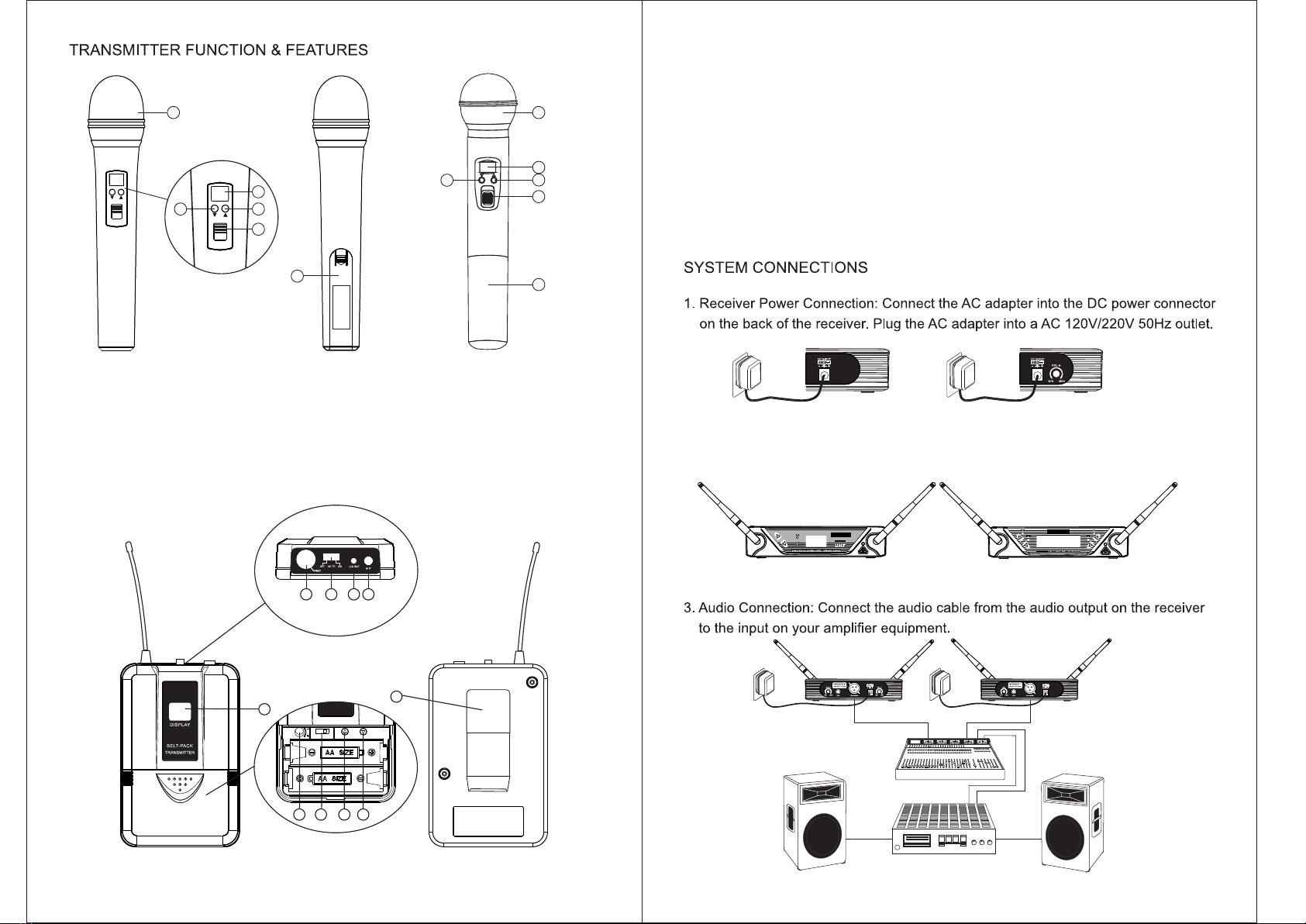
1. Power and Audio Mute Switch.
2. Antenna: Transmit the RF signal of transmitter.
3. Belt Clip: Attach the transmitter to the belt.
4. Audio Input Jack: it is suitable for lavalier system/headset system.
5. Low Battery Indicator: Red light glows when it is lack of power and should
renew the battery.
6. LCD Information Display: Show the transmitter frequency channel ect.
7. Gain Adjusting Volume: Adjust the transmitter audio input gain.
8.State Setting Switch: Set the using state of lavalier system(L)/headset
system(H).
9.Up Function Button: Sets channel data.
10.Down Function Button: Sets channel data.
ANT.BANT.A
ANT.BANT.A
2. Antenna: Keep the position of antenna at a 45 angle from vertical, .(Shown
as below)
14 5 2
3
7 8
6
9 10
1. Grille: Protects the cartridge and help reducing the breath sounds and wind
noise.
2. LCD Information Display: Show the transmitter frequency channel ect.
3.Down Function Button: Sets channel data.
4.Up Function Button: Sets channel data.
5.Power and Audio Mute Switch.
6.Battery Cover: Open it to install the battery.
1
6
ON
ON
4
5
2
3
5 6
OFF
1
2
4
5
3
6

Rotate
counterclockwise
to open.
BODYPACK TRANSMITTER CONNECTION
1. L av al ie r Mi cr op ho ne C o n n e c t i o n : C o n n e c t t h e c o n n e c t e r o f s u p p l i e d
Lavalier microphone to the connecting jack of transmitter (Shown as below)
Set the transmitter work state in wireless lavalier system.
2. H ea ds e t Mi cr oph on e Co nne ct io n: Co nn ec t t he c on ne c te r of s upp li ed
Headset microphone to the connecting jack of transmitter(Shown as below)
Set the transmitter work state in wireless headset system.
TRANSMITTER BATTERY INSTALLATION
1. Battery Installation of Transmitter: Push open the battery cover,Insert the
supplied batteries into battery jar in polarity and cover the battery Cover.
7
460 970
50 164
8
8

9 10
13-15
185MM X 145MM X 43MM
238MM X 50MM X 50MM
100MM X 65MM X 30MM
X 2
7
X 2
7
300mA/500mA
250MM X 51MM X 51MM

FCCwarningstatement
ThisdevicecomplieswithPart15oftheFCCrules.
Operationissubjecttothefollowingtwoconditions:
1)thisdevicemaynotcauseharmfulinterference,and
2)thisdevicemustacceptanyinterferencereceived,
includinginterferencethatmaycauseundesiredoperation.
Changesormodificationsnotexpresslyapprovedbythepartyresponsibleforcompliancecould
voidtheuser'sauthoritytooperatetheequipment.
ThedevicehasbeenevaluatedtomeetgeneralRFexposurerequirement.Thedevicecanbeused
inportableexposureconditionwithoutrestriction.
Thisdeviceoperatesonano‐protection,no‐interferencebasis.Shouldtheuserseektoobtain
protectionfromotherradioservicesoperatinginthesameTVbands,aradiolicenseisrequired.
Forfurtherdetails,consultInnovation,ScienceandEconomicDevelopmentCanada’sdocument
ClientProceduresCircularCPC‐2‐1‐28,VoluntaryLicensingofLicense‐ExemptLow‐PowerRadio
ApparatusintheTVBands.
Table of contents
Popular Microphone manuals by other brands

Sound Sation
Sound Sation VoxTaker 100 USB user manual

IMG STAGE LINE
IMG STAGE LINE TXS-606HT instruction manual

WalimeXPro
WalimeXPro Boya BY-MM1 instruction manual

Clear One
Clear One ACCUMIC 800-157-001 user manual

HQ Power
HQ Power MICPRO10 user manual

WalimeXPro
WalimeXPro Boya BY-M1pro instruction manual


