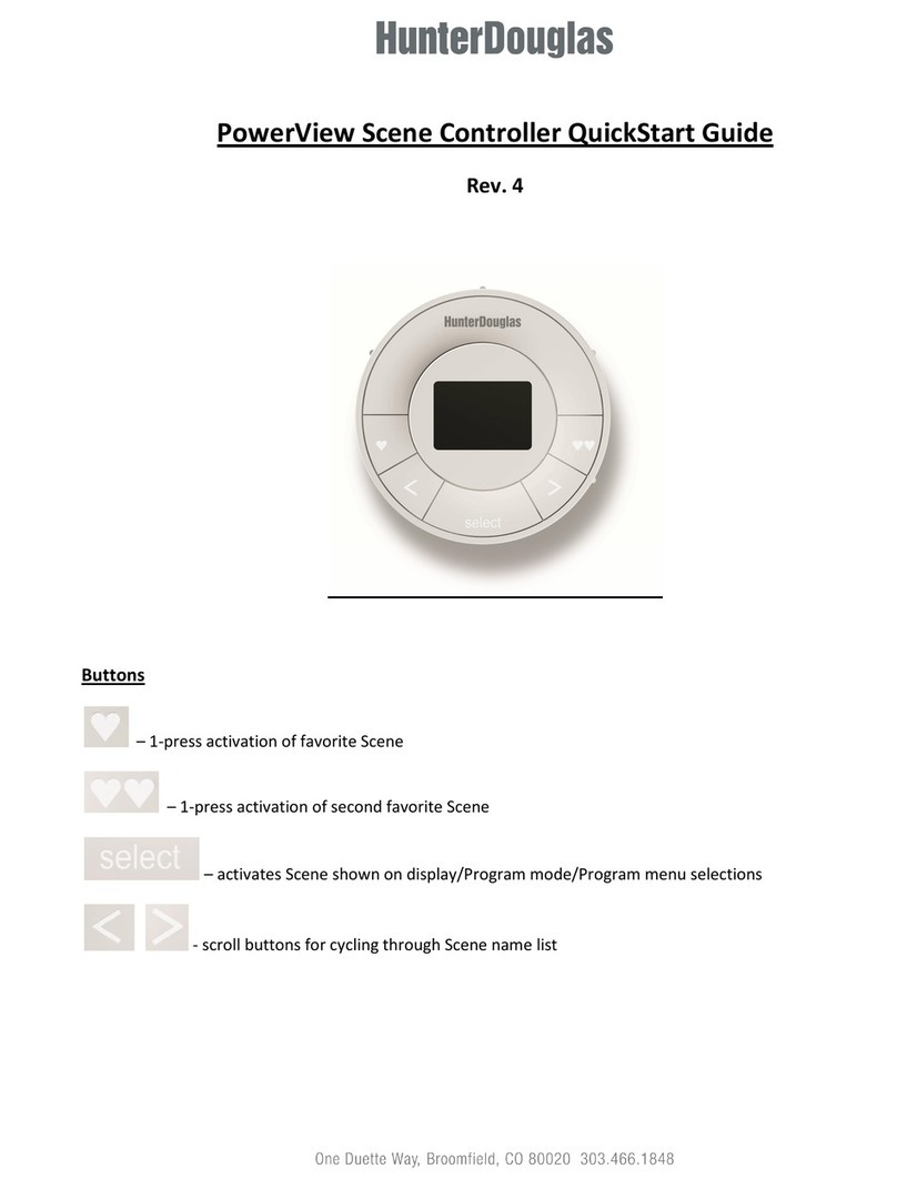
HAVKON INSTRUMENTS ATC-250 User manual

Floor Convector Controller Devices
128X64 Graphic Display
2 –Piece Control Panel (Control Board +
Room Panel)
3 Stage Fan Speed Control
Automatic Heating/ Cooling
Technical Catalog
ATC-250
www.havkon.com ATC-250 ●TR●2020/12/02●● Subject to change without notice Page 1/ 7
Features
• 128X64 Graphic Display
• 2-Piece Control Panel (Control Board + Room Panel)
• 3 Stage Fan Speed Control
• Automatic Heating/Cooling
• Selectable Language Option (Turkish/English)
• Minimum and Maximum Set Temperature Limit
• Weekly Program (Optional)
• Modbus RTU Communication (Optional)
Order Code:
(Room Panel)
Order Code: HCP-ATC-250
(Control Decvices)
Order Code: ATC-250-M
Options:
Weekly program (Optional)
Modbus RTU Communicate (Optional)
General Warnings
Before starting the installation of the device, carefully read the user manual and the
warnings below.
The responsibility belongs to the user in case of damage, loss and accidents caused by
not following the warnings in the user manual. Do not modify or repair the device.
The interventions on the device may cause the device to malfunction and damage the
device and the system.
In these cases, the device is out of warranty for malfunctions.

Technical Catalog
ATC-250
www.havkon.com DMT.HT.1021 ●TR●2020/12/02●Subject to change without notice. Page 2/ 7
Connection
Havkon ATC-250 is a duct type humidity and temperature sensing transmitter. The device must be used in accordance
with the instructions. During installation, there should be no electricity in the connection cables. The device must be
protected from moisture, vibration and pollution. Attention should be paid to the operating temperature. Shielded and
twisted cords should be used in signal, communication input and output lines that are not connected to the network. These
cables should not be passed near high power lines and devices. The screen line should be grounded at the end of the
device side. Installation and electrical connections must be made by technical personnel in accordance with the instructions
in the user manual.
* Supply cables must comply with the requirements of IEC 60227 or IEC 60245
Wiring Diagram
For the most accurate humidity and temperature measurement, the measuring probe tip of the
device should be mounted where there is air flow and below.

Technical Catalog
ATC-250
www.havkon.com DMT.HT.1021 ●TR●2020/12/02●Subject to change without notice. Page 3/ 7
Dimensions
HCP-ATC(Room Panel)
ATC-250(Control Devices)

Technical Catalog
ATC-250
www.havkon.com DMT.HT.1021 ●TR●2020/12/02●Subject to change without notice. Page 4/ 7
Room Panel Use
On/Off Button: It manages the On/Off functions of the device.
Mode Button: Selects the operating mode (Heating or Cooling) of the device.
OK Button: It is used as a confirmation button in device setting selection and mode screens.
Up Button: Increases Set Temperature in Auto mode.
Down Button: Decreases the set temperature in automatic mode.
SETUP Button: It redirects to the User Settings Menu.
In order to enter the User Setting Menu, the SETUP button must be pressed continuously for 2 seconds
on the panel while the device is on.
Key Lock Activation: While the device is on or off, press and hold the SETUP and DOWN buttons
simultaneously for 3 seconds. When you see “KEY LOCK” on the screen, the panel has switched to key
lock. When the device is on, there is a lock sign in the upper corner of the screen.
Disabling Key Lock: While the device is on or off, press and hold the SETUP and DOWN buttons
simultaneously for 3 seconds. When you see "KEY LOCK OFF" on the screen, the panel key lock has
become passive.
Note: If the Controller is connected to the central system via Modbus Communication, the Key Lock can
also be controlled from a remote point.
Weekly Program Setting:
While the device is on, press the SETUP button on the panel for 2 seconds.
From the incoming settings menu, highlight the Weekly Program option and press the
MODE/OK button.
Select the day of the week from the Weekly Program screen with the Up or Down button and
enter the start and end times of the device using the Mode/OK button.
Proceed by pressing the OK Button.
Note1: If the start time is after the end time, the device will remain off during the selected day.
Note2: If the start time and end time are the same, the weekly program application will not work
for the selected day.
Note3: If the device is programmed weekly for the current day and is within the programmed
working hours, the clock logo appears on the screen.
Note4: If the device is programmed weekly for the current day and outside the programmed
working hours, the clock logo stop logo appears on the screen.
Date and Time Setting:
While the device is on, press the SETUP button on the panel for 2 seconds.
From the incoming settings menu, highlight the Date Time Setting option and press the
MODE/OK button.

Technical Catalog
ATC-250
www.havkon.com DMT.HT.1021 ●TR●2020/12/02●Subject to change without notice. Page 5/ 7
Set the date and time using the Up/Down and MODE/OK buttons on the Date Time setting
screen.
Exit by pressing the MODE/OK button.
Language Setting:
While the device is on, press the SETUP button on the panel for 2 seconds.
From the incoming settings menu, highlight the "Language Selection" option and press the
MODE/OK button.
On the "Language Selection" screen, set the language to Turkish or English from the Up or
Down buttons.
Exit by pressing the MODE/OK button.
Screen Lighting Adjustment:
While the device is on, press the SETUP button on the panel for 2 seconds.
From the incoming settings menu, highlight the "Luminous Intensity" option and press the
MODE/OK button.
Adjust the light intensity from the Up or Down buttons on the "Luminous Intensity" screen.
Exit by pressing the MODE/OK button.
Screen Contrast Adjustment:
While the device is on, press the SETUP button on the panel for 2 seconds.
From the incoming settings menu, highlight “Contrast Adjustment” and press the MODE/OK
button.
Adjust the light contrast value from the Up or Down buttons on the "Contrast Adjustment" screen.
Exit by pressing the MODE/OK button.
Attention The changes to be made in the Service Setting Menu must be made by the relevant
technical personnel.
Services Setting
Temperature Sensor Position Setting:
While the device is off on the panel, press the up and down buttons simultaneously for 3
seconds.
Select the “Control Temperature” option from the Service Menu.
From the "Control Temperature" screen, select the position of the Sensor (Panel, External) with
the Up and Down buttons.

Technical Catalog
ATC-250
www.havkon.com DMT.HT.1021 ●TR●2020/12/02●Subject to change without notice. Page 6/ 7
Exit by pressing the MODE/OK button.Delay Time Setting:
While the device is off on the panel, press the up and down buttons simultaneously for 3
seconds.
Select the “Delay Time” option from the Service Menu.
Select the delay time from the "Delay Time" screen with the Up and Down buttons.
Exit by pressing the MODE/OK button.
Control Mode Setting:
While the device is off on the panel, press the up and down buttons simultaneously for 3
seconds.
Select "Control Type" from the Service Menu.
Set the device operation mode (2 Pipes, 4 Pipes, 1 Stage Heater) with the Up and Down buttons
on the “Control Type” screen.
Exit by pressing the MODE/OK button.Fan Level Setting:
While the device is off on the panel, press the up and down buttons simultaneously for 3
seconds.
Select the “Fan Level” option from the Service Menu.
Adjust the levels of the 3-stage fan separately with the Up and Down buttons on the “Fan Level”
screen.
Exit by pressing the MODE/OK button.
Panel Communication Setting:
While the device is off on the panel, press the up and down buttons simultaneously for 3
seconds.
Select the "Panel Setting" option from the Service Menu.
Select the first “Modbus ID” from the “Panel Setting” screen with the Up and Down buttons.
Press the MODE/OK button to switch to the Modbus Baudrate Value Screen.
On the “Modbus Baudrate” screen, select the Baudrate(1200Bps, 2400Bps, 4800Bps, 9600Bps,
19200Bps,38400Bps).
Exit by pressing the MODE/OK button.
Note1: Panel communication works with Modbus RTU protocol over RS485 Line. Panel
communication port in desired applications (It can also be operated with devices such as PC,
Scada, PLC, HMI.)
Note2: Communication Settings: Data Bits:8, NoneParity Stop Bit 1
BMS Modbus Communication Setting :
While the device is off on the panel, press the up and down buttons simultaneously for 3
seconds.Select “Modbus Setup” from the Service Menu.

Technical Catalog
ATC-250
www.havkon.com DMT.HT.1021 ●TR●2020/12/02●Subject to change without notice. Page 7/ 7
Select the first “Modbus ID” from the “COM2 Setup” screen with the Up and Down buttons.
Press the MODE/OK button to switch to the Modbus Baudrate Value Screen.
On the “Modbus Baudrate” screen, select the Baudrate (1200Bps, 2400Bps, 4800Bps,
9600Bps, 19200Bps,38400Bps).
Exit by pressing the MODE/OK button.
Note1: Building automation communication works with Modbus RTU protocol over RS485 Line.
Panel communication port in desired applications (It can be operated with devices such as PC,
Scada, PLC, HMI.)
Note2: Communication Settings: Data Bits:8, NoneParity Stop Bit 1
Panel Factory Reset:
While the device is off on the panel, press the up and down buttons simultaneously for 3
seconds.
Select “Factory Reset” from the Service Menu.
From the "Factory Reset" screen, select "ON" with the Up and Down buttons.
Exit by pressing the MODE/OK button.
The Room Panel will return to the Factory Settings.
Panel Factory Setting:
Light Intensity: %50
Contrast Adjustment: %50
Panel Communication: Modbus ID: 1
Modbus Baudarate: 9600 Bps
Control Card Factory Reset:
Press and hold the button on the Control Card while the device is energized. The green led on
the control card will start to flash. The green led will stay on for 2 seconds and then you can
remove your hand from the button when it goes out.Mainboard Factory Reset:
Device Status: Off
Device Mode: Heating
Set Temperature: 23
Table of contents

