6
Overview
4. Wiring
The connector, and zero / span potentiometers are under the cover. Test nipples for calibration
of the SERIES 8000 and SERIES 8000-SAN are available on request.
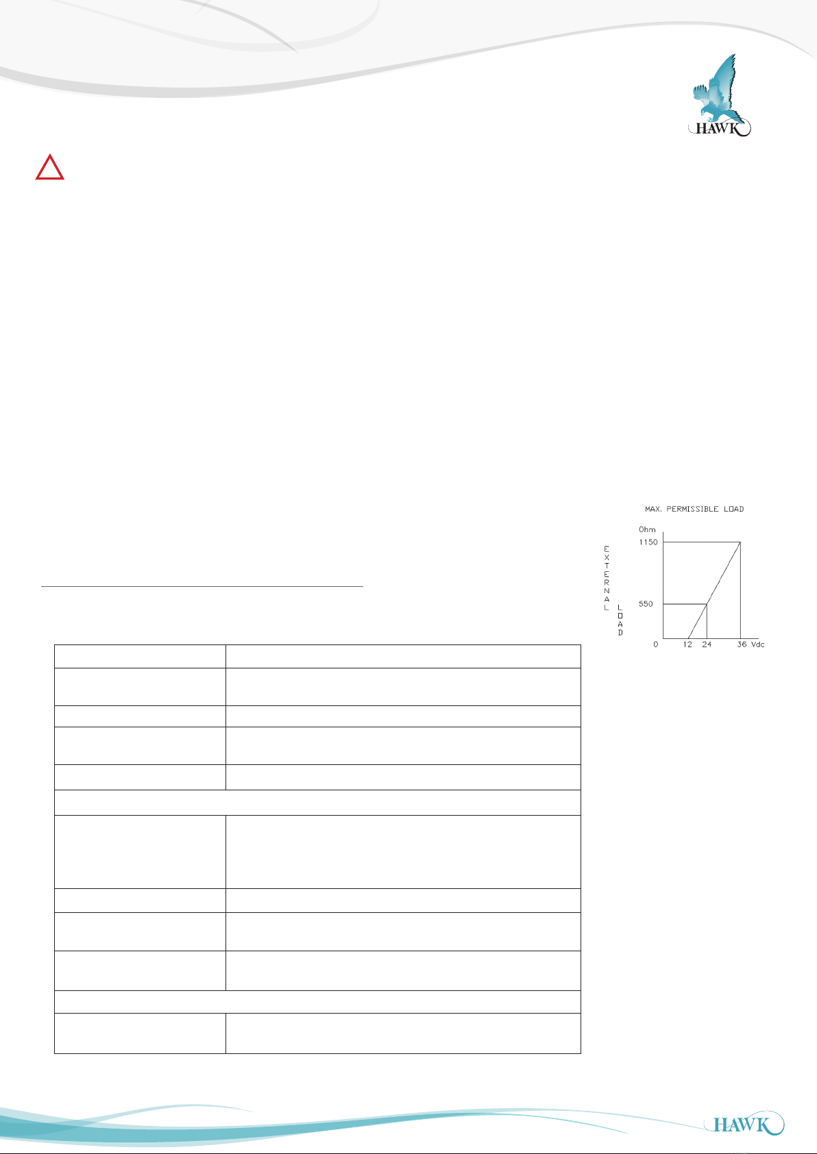
External loads must be placed in the negative side of the 2- wire loop..
The figure right shows the wiring connection of the transmitter. The 2-wires must be connected
to connectors 3 (-) and 4 (+) of the terminal board.
The transmitter must always be connected to earth.
The signal wiring must be shielded and twisted pair yield the best results. DO NOT run signal
wiring in open trays with power wiring, or near “heavy” electrical equipment (E.g. Frequency
controllers or heavy pumps).
Shielding must always be connected at the side of the power supply. In case the mounting
position is already connected to earth (e.g. via the tank or pipe line) do NOT connect the
instrument to ground. Please ensure that the instrument is not connected to ground twice to
prevent the occurrence of an ‘earth loop’.
4.1 Digital Local Indicator
The local indicator displays a digital value that is proportional to the pressure measured by the transmitter. The full scale point may
be set to any value between 0000 and 1999. The local indicator can be mounted afterwards. Remove the bridge which is placed
between connector (1) and (2). Connect the red (+) wire to (1) and the black (-) wire to (2). When using a local indicator the minimum
power supply must be 15,5 Vdc.
4.2 Hazardous Area
The SERIES 8000 and SERIES 8000-SAN can be certified for applications in hazardous areas.
When the transmitter is used in such areas, use a certified power supply, from 13 – 26,5 Vdc. Installation of this device has to be
carried out by a certified and qualified mechanic or a certified and qualified installer.
4.3 Certication
ATEX - II 1 G Ex ia IIC T4 Ga
Certificate : KEMA 03ATEX1219 X
Ui = 26,5 Vdc, Ii = 110 mA, Ci = 1 nF, Li = 1.2 mH, Pi = 0,9 W
-30° C < Tamb < 70° C
The X in the certificate number refers to a special condition only applicable for our submersible level transmitter “HYDROBAR” –cable
and –FR. See for this conditions the ATEX-certificate.
The maximum length of the cable for the Series-8000-cable, Series-8000-SAN-cable and Hydrobar-cable is 32 m. Electrostatic
charging of the cable and the protection cap by the flow of non-conductive media (e.g. in stirring vessels or pipes) shall be avoided.
IECEx - Ex ia IIC T4 Ga
Certificate: DEK 13.0060X
Ui = 26.5 Vdc, Ii = 110 mA, Ci = 1 nF, Li = 1.2 mH, Pi = 0.9 W
-30° C < Tamb < 70° C
All certifications are in compliance with IECEx scheme rules, and the International Standards : IEC 60079-0:2011, IEC 60079-
11:2011, IEC 60079-26:2007 and IEC 17050-1. They are certified for use in hazardous areas by DEKRA B.V.
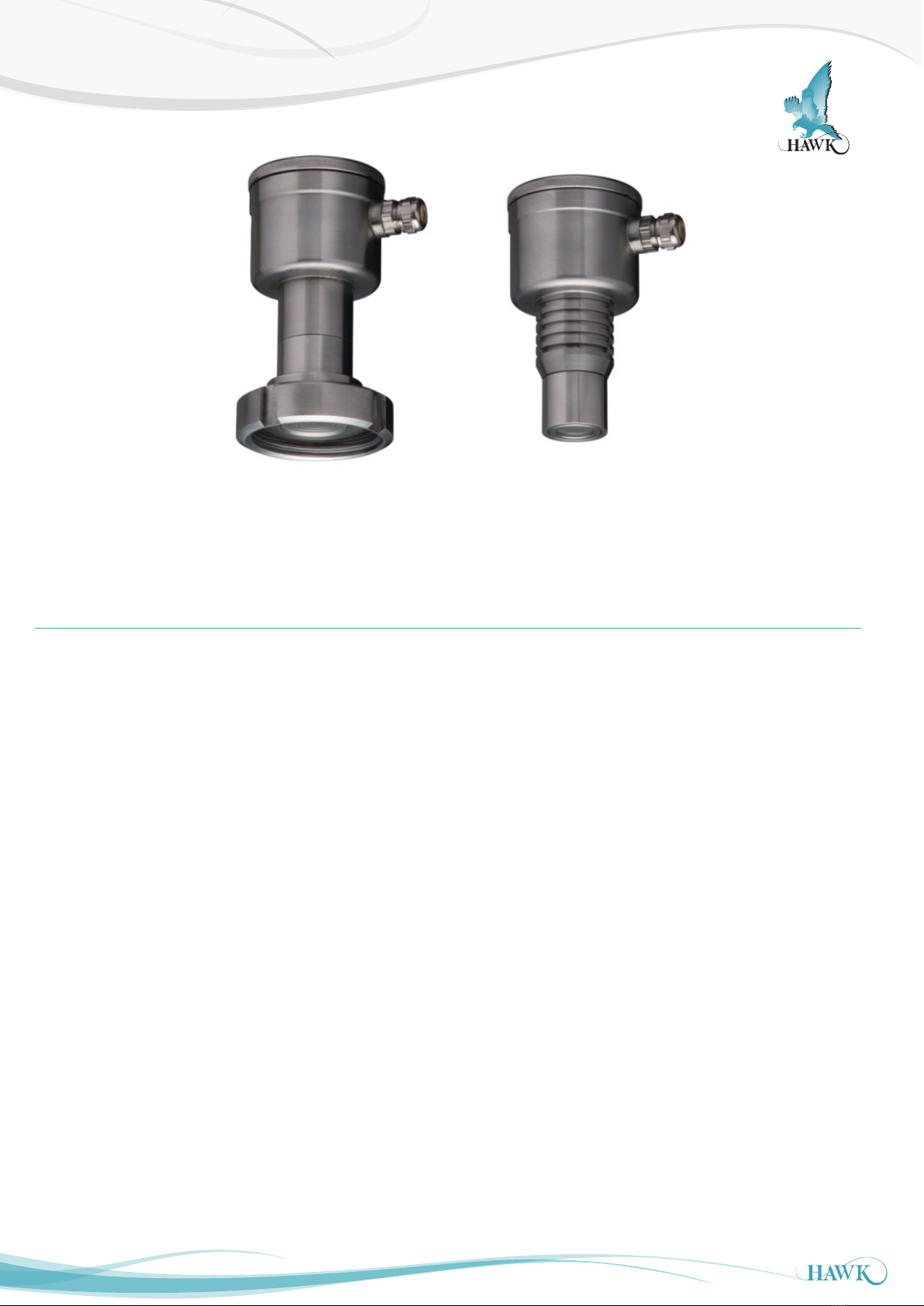
Series 8000-SAN / Series 8000
Reversing the polarity will not damage the transmitter, but the transmitter will not function until the + and – are properly connected.