Hawke 501/RCG User manual
Product Assembly Instructions
501/RCG Coupler
AI 2046 - Issue D / 24/05/2021 / Page 1 of 7
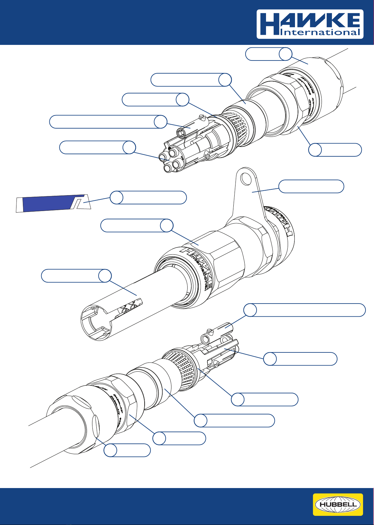
Backnut8
Armour Spigot5
Socket Contact with Grub Screw4
Component Parts - 501/RCG Coupler
Armour Clamp Ring6
Middlenut7
Socket Contact with Grub Screw 4
Armour Spigot 5
Socket Insert (Alt)*
3
Backnut 8
Armour Clamp Ring 6
Middlenut7
In-Line Pin Insert 2
Coupler Housing 1
* Supplied socket inserts are coloured black (standard) or natural (alternative). Parts are dimensionally
identical but the pin numbering is inverted to ensure correct through numbering.
Socket Insert (Std)* 3
Threadlock Sachet9
Integral Earth Tag

Part A: Installing 501/RCG Coupler
Seal/Ring Size
Dim Os-A B
y50mm min
25mm20mm
x
Strip Lengths
Armour Clamp Ring Orientation
Gland
Size
Os-A
Orientation
0 - 0.8mm0.8 - 1.25mm
B0 - 0.7mm1.25 - 1.6mm
Equipment Side Equipment Side
x
Tape Armour
After tape is spread, ensure ends are
trimmed at 90° as shown
STEP A2: Prepare Cable A
Slide backnut (8), middlenut (7) and armour clamp ring (6) onto cable A.
Conrm orientation of armour clamp ring is correct (see table below).
Cut cable length, strip outer sheath and cut armour. Use lengths as shown in table below.
STEP A3: Remove socket insert (3) from spigot (5)
Squeeze base of insert (3) and remove from the spigot (5) as shown.
STEP A4: Slide spigot (5) onto cable
Push spigot shoulder up to armour/braid. Slide clamping ring (6) up to the armour/braid by hand
x
y
AI 2046 - Issue D / Page 2 of 7
Images for illustration purposes only.
Product supplied may dier from that shown.
6
78
35
6
5
STEP A1: Confirm Cable Lengths
The 501/RCG Coupler is an inline enclosure used to terminate two ends of cable together.
Conrm the cables are long enough by ensuring that as a minimum the ends meet.
Cable A
Cable B
Ends Meet

STEP A6: Clamp Armour/Braid
Slide coupler housing (1) over cable until it meets the spigot. Slide middlenut (7) up to coupler housing and hand tighten.
Grip the coupler housing (1) with a spanner/wrench. Use a second spanner/wrench to tighten middlenut (7) half to three quarters of a turn.
STEP A7: Inspect Armour/Braid
Unscrew the middlenut (7). The armour clamp ring (6) should now be locked in place.
Visually inspect that the armour/braid has been successfully clamped between the spigot (5) and the armour clamp ring (6). If clamping is
not satisfactory, repeat step 6.
Cut inner sheath in line with edge of spigot (5) and strip to expose cores.
STEP A8: Fit socket insert
Take socket insert (3) and review numbering on tip. Feed cable cores through the correct slot in the socket insert. Slide the socket insert (3)
down to the spigot (5) until it clicks in place.
*Click*
AI 2046 - Issue D / Page 3 of 7
Images for illustration purposes only.
Product supplied may dier from that shown.
7
1
67
15
3
5
STEP A5: Remove Insert (2) From Coupler Housing (1)
Slide insert (2) out from Coupler Housing (1) and put to one side.
Std insert as shown
Alt insert positions 1 & 3 reversed
1
2
STEP A9: Cut conductors to length and strip
Cut conductor to 26mm from top of spigot. Use the groove indicator in the
insert as a visual aid. The conductor should not extend past this cut line.
Strip conductor back past the insert shoulder which indicates the strip line.
TIP: Use a pen to mark cores in situ then remove insert to aid conductor
strip process.
The socket insert (3) may be removed from the spigot (5) to assist cable
stripping process then re installed as shown in step 3.
26mm
Cut line
Strip line
3
5
10mm
Grip here
with wrench

AI 2046 - Issue D / Page 4 of 7
Images for illustration purposes only.
Product supplied may dier from that shown.
STEP A10: Fit contacts to cable conductors
Take the rst contact (4), slide over the conductor and press into slot in the insert (3). The contact (4) will now be retained in the insert (3).
Repeat for all remaining contacts
STEP A11: Check alignment of contacts
Firstly conrm all contacts (4) are concentric to the openings in the tip of the insert.
Then ensure the contacts (4) are correctly rotated so that the grub screw is in the centre of the slot.
STEP A12: Apply threadlock and tighten grubscrews
Take the threadlock sachet (9) supplied with the product and tear open. Dispense a drop of threadlock onto the exposed thread of one
contact grub screw. Tighten the grubscrew with a small screwdriver. Recommended torque is 0.75Nm. Wipe away any excess. Repeat for all
contacts.
3
4
9
STEP A13: Repeat process for Cable B
The body portion of the product is now terminated onto cable A. Repeat steps A2-A12 for cable B.
Now the body portion is terminated onto both cables and is ready for coupling.
Cable A Cable B
STEP A14: Plug insert into one of the terminated cables
Align the keyways and slide the in-line pin insert (2) over the body portion until the contacts engage.
Align Keyways 2
10 20 30 405 15 25 35 45
10 20 30 40

AI 2046 - Issue D / Page 5 of 7
Images for illustration purposes only.
Product supplied may dier from that shown.
STEP A15: Tighten Middlenut (7)
Slide the coupler housing (1) over the in-line pin insert (2). Hand tighten the middlenut into the coupler body. Use a wrench
to ensure the coupler body cannot turn. Use a second wrench to apply a further 1/4 turn to the middlenut.
STEP A16: Install backnut (8)
Tighten the backnut (8) by hand until a seal is formed around the cable. Use a wrench/spanner to grip the middlenut (7).
While preventing the middlenut (7) turning, use a second wrench to apply one further full turn to the backnut (8).
Use the middlenut guide as an indication that the backnut is in the correct position to suit cable diameter.
A diameter scale below is provided to assist in this process.
STEP A17: Engage second body into coupler housing (1)
Take second terminated cable. Ensure keyway is aligned and push second cable into coupler housing (1) until contacts are
engaged.
Align Keyways
STEP A18: Install Middlenut and Backnut
Repeat steps A15 & A16 for cable B. The installation of the 501/RCG Coupler is now complete.
7
71
2
87
1
Grip here
with wrench
Grip here
with wrench
Diameter Scale (mm)
Correct when printed A4 Booklet Style
50 60 70 80
50 60 70 80
55 65 75

AI 2046 - Issue D / Page 6 of 7
Images for illustration purposes only.
Product supplied may dier from that shown.
Part B: Decoupling 501/RCG Coupler
STEP B1: Loosen Backnut
Grip the middlenut using a wrench to prevent it turning.
Use a second wrench to undo the backnut until loose (minimum 2 turns)
STEP B2: Undo Middlenut (7)
Grip the coupler housing (1) using a wrench to prevent it turning. Use a second wrench to undo the middlenut (7) until loose.
The middlenut (7) and backnut (8) can now be slid down the cable.
STEP B3: Slide body out from housing
The body portion may now be pulled out from the coupler housing (1) and decoupling is complete.
1
Grip here
with wrench
Grip here
with wrench
WARNING: DO NOT DECOUPLE WHEN ENERGISED. SYSTEM MUST BE DE-ENERGISED WHEN COMMENCING THIS PROCEDURE
CAUTION: DO NOT UNDO MIDDLENUT (6) UNTIL PRODUCT IS DECOUPLED. UNDOING THE MIDDLENUT WHILST BACKNUT IS TIGHT RISKS
DAMAGE TO THE PRODUCT.
8
7
8
7
1
1

On behalf of the aforementioned company, I declare that, on the date the equipment
accompanied by this declaration is placed on the market, the equipment conforms
with all technical and regulatory requirements of the listed directives.
Declaration of Conformity In Accordance With European Directive 2014/34/EU and UK Directive S.I. 2016/1107
Provisions of the Directive fulfilled by the Equipment: II 2 GD Ex eb IIC T6/T5 Gb, Ex tb IIIC T80°C/95°C Db
Harmonised Standards used: EN 60079-0:2018, EN60079-7:2015+A1:2018, EN60079-31:2014
Notified Body for EU-Type Examination: CML B.V. 2776 Amsterdam, NLD
EU-type Examination Certificate: CML20ATEX3217
EU Notified Body for Production: 0598
Approved Body for UK-Type Examination: CML 2503 Chester, UK
UK-type Examination Certificate: CML21UKEX3073X
UK Notified Body for Production: 1180
A. Reid
Technical Manager
A member of the Hubbell Group of Companies
Hawke International is a division of Hubbell Ltd.
Registered No. 669157 in England. Registered Oce:
Cannon Place, 78 Cannon Street, London EC4N 6AF.
www.ehawke.com
UK Oce
Oxford Street West,
Ashton-Under-Lyne,
Lancashire. OL7 0NA. UK
Sales: +44 (0) 161 830 6698
Technical: +44 (0) 161 830 6697
Fax: +44 (0) 161 830 6648
E-mail: [email protected]
Technical Information
501/RCG Coupler
AI 2046 - Issue D / Page 7 of 7
501/RCG COUPLER SELECTION TABLE
Seal/Ring
Size
Across
Flats
Across
Corners
Max Hexagon
Dimensions
Os
A 14.3
24.0
30.0
26.5
32.5
Outer
Sheath
Cable Acceptance Details
8.1
Min. Max.
5.5
12.5
12.0
20.5
Max.
Steel Wire Armour/
Tape/Braid
O 24.0 26.511.4 9.5 16.0
Orientation 1 Orientation 2
0.8/1.25
0.8/1.25
0/0.8
0.8/1.25 0/0.8
0/0.8
Inner
Sheath
Body
Size
4-pin
6-pin A
B
14.3
19.7
30.0
36.0
32.5
39.5
12.5
16.9
20.5
26.0
O 24.0 26.511.4 9.5 16.0
0.8/1.25
1.25/1.6
0.8/1.25 0/0.8
0/0.8
0/0.7
TECHNICAL DATA
Product Type: 501/RCG Coupler
Equipment Type: Group II Hazardous Area
Ingress Protection: IP66, IP67
Operating Temp: -60°C to +60°C
Conductor Sizes: 0.75mm2- 6mm2
Max Conductor Dia: Ø5.50mm
INSTALLATION NOTES
1. WARNING: Do not connect or disconnect when Energised.
2. Product must be installed by a suitably trained and competent individual.
3. Internal earth provided through internal armour clamping arrangement.
For external earth provided through supplied earth tag.
SPECIAL CONDITIONS OF USE
1. Do not disconnect product when energised.
2. The socket grub screws shall be tighten and secured by thread locking
compound
3. When a coupler is tted with an adapter, a suitable cable gland shall be
tted
4. Product may not be left uncoupled in a hazardous areas
5. Product Ambients:
- For T6/T80°C applications, the upper ambient temperature shall not
exceed +60°C.
- For T5/T95°C applications, the upper ambient temperature shall not
exceed +50°C
TORQUE VALUES
All torque values below were generated on metallic mandrels. For cable, it is
recommended that the assembly instructions are followed.
ELECTRICAL SPECIFICATION:
Voltage Rating: 300Vac; 212Vdc
Ampage and T-Class:
Other conductor sizes between the sizes of 0.75mm2- 6mm2may be used.
If the conductor size is not stated in the table above, the max ampage is
restricted to the closest size rounded down.
E.g. 3mm2conductor size would be limited to 10A if used in a T6 classication.
CERTIFICATION DETAILS
II 2 GD Ex eb IIC T6/T5* Gb, Ex tb IIIC T80°C/95°C* Db
ATEX: CML 20ATEX3217X IECEx: IECEx CML 20.0137X
1Ex e IIC T6/T5* Gb X, Ex tb IIIC T80
°C
/T90
°C
* Db X
EAC: RU C-GB.HA91.B.00207/21
*Temperature Class is dependent on the ampage applied and conductor size.
See table above for details.
Additional Approvals
UKCA: CML 21UKEX3073X Inmetro: IEx 21.0011X
Os O A
Torque Figures N/m
Seal Size
Backnut Torque
B
201212 30
T6 +60°C
T-Classes and Ampage
Conductor Size
0.75mm2
1.5mm2
2.5mm2
4mm2
6mm2
T5 +50°C
5A
10A
12A
20A
5A
10A
18A
30A (4pin)
25A (6pin)
Other manuals for 501/RCG
1
Table of contents


