ACCESSORIES:
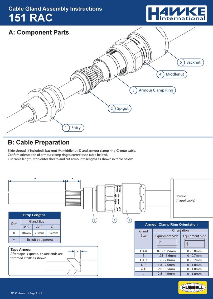
Before cable gland assembly or stripping of the cable gland
assembly, consideration should be given to any cable gland
accessories that may be required, such as: -
Shroud, to oer additional corrosion protection.
Locknut, to secure cable glands into position.
Sealing washer, to oer additional ingress protection of the
enclosure at the cable gland entry.
Earthtag, to provide an external armour/braid bonding point.
Serrated washer, to dampen any vibrations that may loosen the
locknut or cable gland assembly.
SCHEDULE OF LIMITATIONS:
1. The cable glands when used with braided cable types are only
suitable for use with xed apparatus, the cable for which must
be eectively clamped and cleated elsewhere.
2. This cable gland has an operating temperature range of -60°C
to +80°C.
3. A seal must be formed between the equipment and the cable
gland to maintain the appropriate degree of protection against
ingress of dust, solid objects and water.
AI 312 - Issue R / Page 2 of 2
EU Declaration of Conformity in accordance with European Directive 2014/34/EU
Manufacturer: Hawke International
Address: Oxford Street West, Ashton-under-Lyne, OL7 0NA, United Kingdom.
Equipment: Group II Compression Cable Glands Type: PSG 553/RAC
Provisions of the Directive fullled by the Equipment:
Group II Category 2GD Exeb IIC Gb, Exdb IIC Gb, Extb IIIC Db – IP66
Notied Body for EU-Type Examination: SGS-Baseefa 1180 Buxton UK
EU-type Examination Certicate: Baseefa06ATEX0056X
Notied Body for production: SGS-Baseefa 1180 Buxton UK
Harmonised Standards used:
EN60079-0:2012+A11:2013, EN60079-1:2014, EN60079-7:2015, EN60079-31:2014.
On behalf of the above named company, I declare that, on the date the
equipment accompanied by this declaration is placed on the market, the
equipment conforms with all technical and regulatory requirements of the above
listed directives.
………………………………….
A. Tindall
Technical Manager
F
Select the correct punch tool to suit the
conductors sizes (see table) and cut out the
required number of holes in the seal
using the
indented positions as a guide. Remove the entry
and pass the individual conductors through
the appropriately sized punched holes in the seal
ensuring they are not twisted or kinked, and
slide the seal
down to the spigot
.
Replace entry
and re-assemble middle nut
onto the entry component
.
Tighten up the middle nut
until hand tight,
then using a wrench/spanner turn the nut
through a minimum of one full turn.
Hand tighten the backnut
to form a seal
around the cable, then tighten a further full turn
using a wrench/spanner. Ensure that the middle
nut
does not rotate when tightening the
backnut
. Ensure that the deluge seal is pulled
down into position, if tted.
Locate the shroud over the cable gland, if
applicable.
E
Unscrew the middle nut
and visually inspect that
the armour/braid has been successfully clamped
between the armour spigot
and the armour
clamping ring
. If armour/braid not clamped, repeat
assembly.
Note : If the equipment has a threaded entry, it may be
advisable to screw the cable gland into the equipment to
prevent twisting of the cable after Step E
D
Hold the entry
in position with a spanner/wrench to
prevent rotation. Hand tighten the middle nut
to the
entry
and turn a further ½ to ¾ of a turn with a
spanner/wrench.
IMPORTANT:Support the cable to prevent it from
twisting.
12.5
16.9
22.0
20.5
26.0
33.0
Outer Sheath
Min. Max.
0.8/1.25
1.25/1.6
1.6/2.0
0/0.8
0/0.7
0/0.7
Steel Wire Armour/
Tape/Braid
Orientation
2
Orientation
1
CABLE GLAND SELECTION TABLE
Male Entry
Thread Size
Metric
Size
Ref. NPT
Across
Flats
Across
Corners
Hexagon
Dimensions
A
B
C
M20
M25
M32
30.0
36.0
46.0
32.5
39.5
50.5
53.0
69.5
64.0
80
88
95
½" - ¾"
¾" - 1"
1" - 1¼"
Compressed
Length
Maximum
Length
CABLE GLAND SIZE FOR CONDUCTOR
Maximum No.
of Cores
A & B
7
4
3
1.5 2.5
Cores Cross Sectional Area mm²
4.0 6.0 10.0
---
------
---
---
---
---
---
A & B B & C C
B
C
B
PUNCH TOOL SIZE DETAILS
Punch Ref.
Core C.S.A. mm²
No.1 No.2 No.3
1.5 - 2.5 4.0 - 6.0 10.0
6
2
1
6
3
2
1
1
2
65
4

