Hawke Power Ex User manual

Power
POWER CONNECTOR
TERMINATION / HOOK UP
PROCEDURE
(AI365 Rev 5 – 01Mar16)
Hawke International
UK Office,
Oxford Street West,
Ashton-under-Lyne,
Lancashire.
OL7 0NA. UK
Sales: +44 (0) 161 830 6698
Technical: +44 (0) 161 830 6697
Fax: +44 (0) 161 830 6648

Power Termination Procedure (AI365 Rev 5 – 01Mar16)
CP / CR PROCEDURE
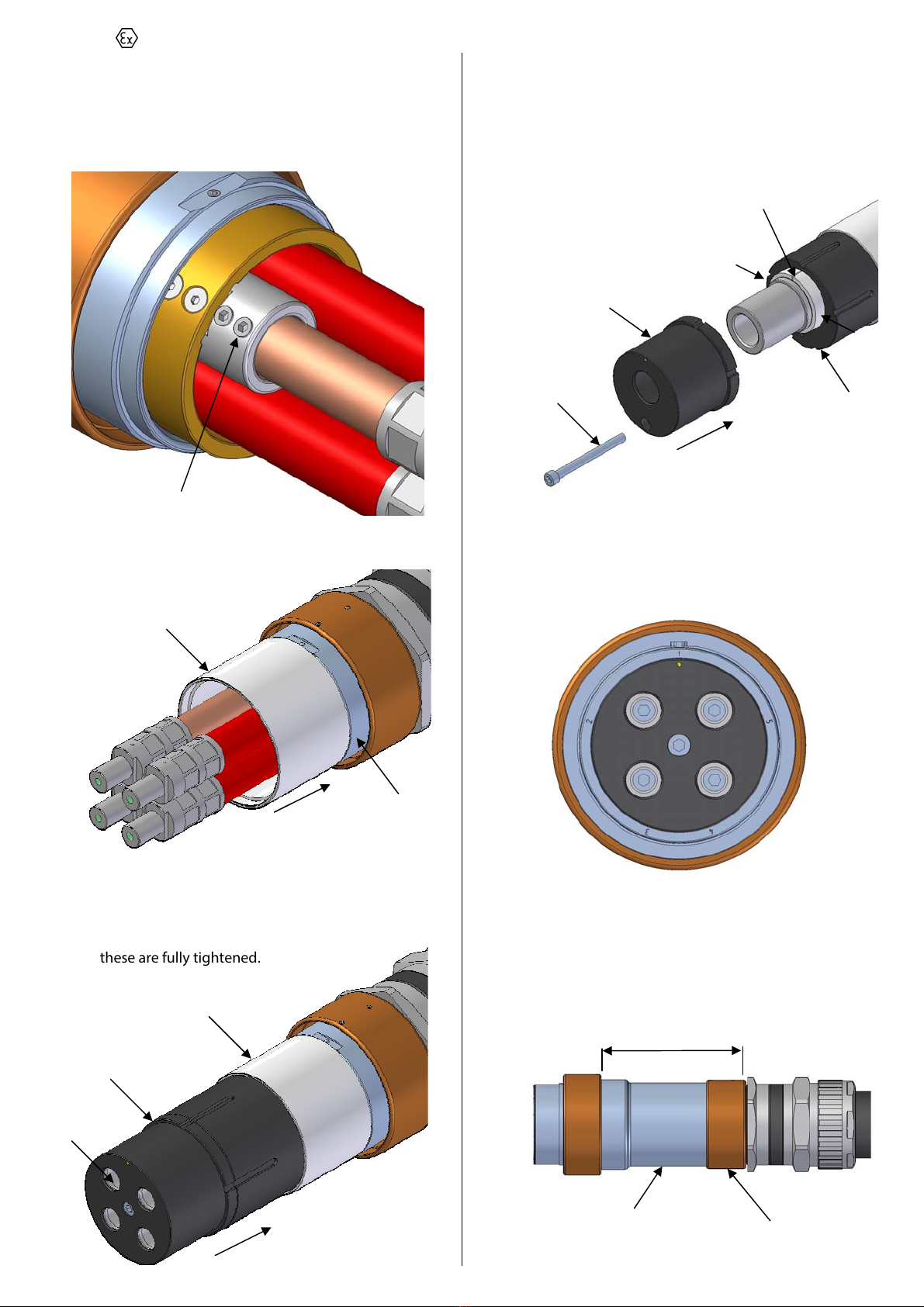
1) Terminate the cable into the Exd cable gland as per the
manufacturer’s instructions. Consider at this stage the
relative position of the phases.
2) Cut the conductors to the lengths shown.
(For earth conductors which are being terminated to the
earth ring (see step 6) but not carried through the
contact, cut back X = 100mm for all sizes, see 10 - 13)
3) Strip back the insulation as shown. (For all earth
conductors terminated via the internal earth ring, cut
back the insulation flush with the gland entry thread, see
10 - 13).
4) Unscrew the rear engaging nut from the CP / CR shell.
Remove the rear shell, spacer tube and insert from the
CP / CR shell.
5) a) CONTACT SIZES 50 - 240mm².
Remove the screws from the front of the contacts
only and push the crimp lugs out of the insert.
b) CONTACT SIZES 300 – 630mm².
Remove the screw from the plastic housing and
remove the contact from inside.
CP / CR SHELL
INSERT
SPACER TUBE
REAR SHELL
ENGAGING NUT
REMOVE CONTACT
SCREWS
CRIMP LUGS
HOUSING SCREW
CONTACT
X mm
Y mm
CONTACT SIZE X mm (± 1.5mm)
50mm² 147
70mm² 147
95mm² 147
120mm² 146
150mm² 146
185mm² (ExP 40 & 50) 149
185mm² (ExP 75) 159
240mm² (ExP 40 & 50) 149
240mm² (ExP 75) 159
300mm² 167
400mm² 172
500mm² 188
630mm² 188
CONTACT SIZE Y mm (± 1.5mm)
50mm² 30
70mm² 30
95mm² 32
120mm² 32
150mm² 32
185mm² 40
240mm² 45
300mm² 50
400mm² 57
500mm² 62
630mm² 67
IMPORTANT NOTE
Hawke International does not recommend the use of their Power Connectors in applications where rigid PVC / SWA / PVC
power cabling (typically to BS 6346 standards) is used in portable / semi-portable applications.
In addition, Hawke recommends that barrier type glands are fitted to flexible power and loose filled control cabling entering the
connectors to maintain the Exd protection concept and to reduce the potential for core movements within the cable being
transferred to the connector’s internal components.

Power Termination Procedure (AI365 Rev 5 – 01Mar16)
6) Remove the internal earth ring from the rear shell sub
assembly by backing off the 2 grub screws on the flats. If
internal earthing is not required, the internal earth ring
assembly along with the fixing grub screws should be
discarded.
7) Crimp the lugs or contacts onto the conductors
(excluding internal earth wire if being used) using
suitable crimp tool. (Hawke recommend Elpress crimp
tools). Contact sizes of 185mm² and larger should be
adjacently double crimped as shown.
8) Feed the conductors through the rear shell assembly and
screw this onto the cable gland entry thread ensuring
the sealing washer is present.
9) Measure the distance from the front of the rear shell to
the end of the crimp lug (50 – 240mm²) or contact (300 -
630mm²). It should be as shown. If not, remove the rear
shell and add or remove the spacer washers supplied to
get the required length. At least 1 washer must be
present to maintain IP rating.
Internal earth procedure (skip to step 13 if not used or
you have single phase connector).
10) Slide the internal earth ring down over the conductors
with the lug going over the bare earth wire.
11) Position the internal earth ring inside the rear shell and
tighten the grub screws into the groove on the earth
ring. Excessive force could distort rear shell.
CRIMP HERE
REAR SHELL ASSEMBLY
1.5mm SEALING / SPACER WASHER
GRUB SCREWS
INTERNAL EARTH
RING
GRUB SCREWS
INTERNAL EARTH RING
EARTH WIRE
Z mm
CONTACT SIZE Z mm
50mm² 111 +0/-4
70mm² 111 +0/-4
95mm² 111 +0/-4
120mm² 111 +0/-4
150mm² 111 +0/-4
185mm² (ExP 40 & 50) 111 +0/-4
185mm² (ExP 75) 121 +0/-4
240mm² (ExP 40 & 50) 111 +0/-4
240mm² (ExP 75) 121 +0/-4
300mm² SKT 161 ±1
300mm² PIN 151 ±1
400mm² SKT 161 ±1
400mm² PIN 151 ±1
500mm² SKT 171 ±1
500mm² PIN 161 ±1
630mm² SKT 171 ±1
630mm² PIN 161 ±1
Power Termination Procedure (AI365 Rev 5 – 01Mar16)
12) Tighten the 2 grub screws on the internal earth lug into
the earth conductor as tight as possible so that the earth
wire is sufficiently clamped. If earth is to be carried
through to a contact, crimp contact prior to tightening
grub screws.
13) Slide the spacer tube over the conductors and onto the
rear shell.
14) a) CONTACT SIZES 50 - 240mm².
Push the insert assembly fully onto the crimp lugs.
The insert should push inside the spacer tube. Refit
the 4 screws into the ends of the contacts. Ensure
these are fully tightened.
b) CONTACT SIZES 300 – 630mm².
Push the rear retainer over the contact. Place the
split tube around the contact. Slide the front contact
retainer over the contact and split tube. Slide the
rear contact retainer over the rear of the contact and
tighten the screw fully.
15) Slide the CP / CR shell over the insert and line the yellow
dot on the insert up with the required keying position 1
to 5 marked on the CP / CR shell.
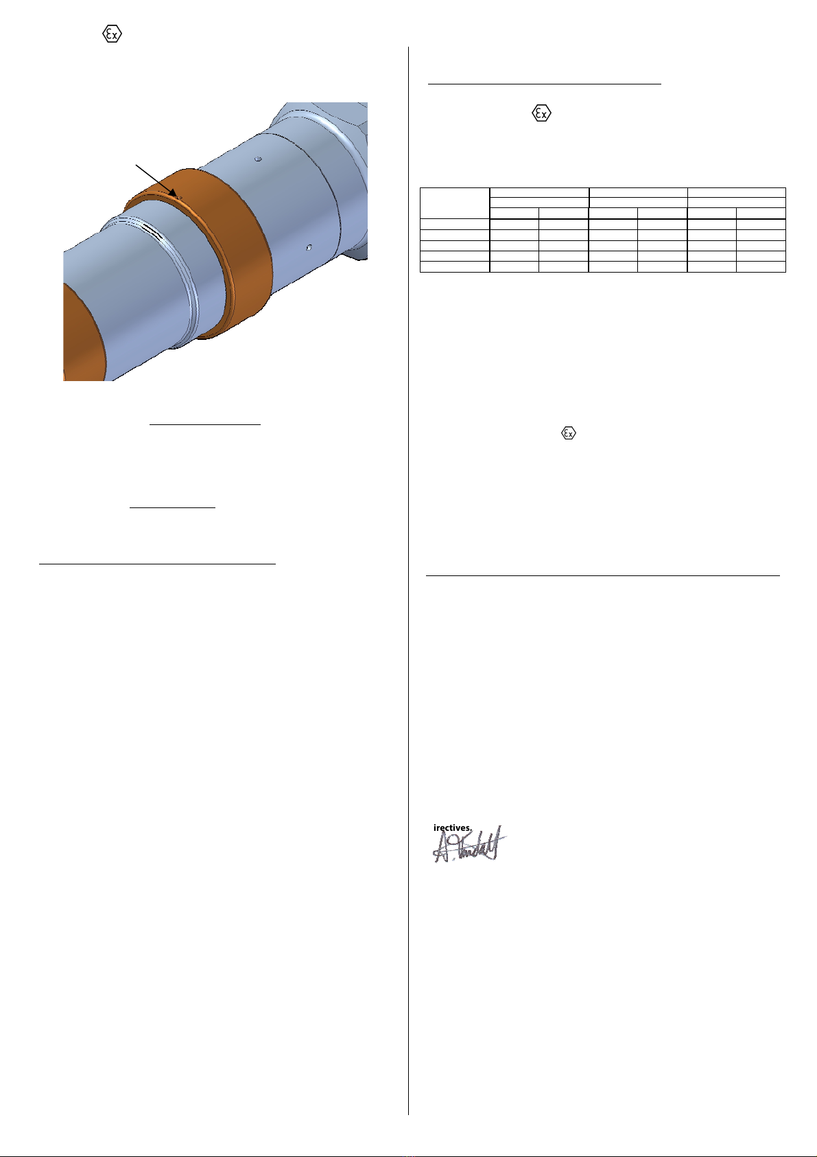
16) Screw the rear engaging nut fully onto the CP / CR shell.
Measure the distance between the front of the rear
engaging nut to the back of the engaging nut which
should be no greater than the distance shown.
GRUB SCREWS
SPACER TUBE
REAR SHELL
SPACER TUBE
INSERT ASSEMBLY
REFIT SCREWS
REAR RETAINER
FRONT RETAINER
SPLIT TUBE
SCREW
Should be tight fit, Dictated by
spacer washers from step 9.
REAR ENGAGING NUT
CP / CR SHELL
Ex32P
–
Ex63P = 154.5mm
Ex75P = 164.5mm

Power Termination Procedure (AI365 Rev 5 – 01Mar16)
17) Tighten down the 2 grub screws on the rear engaging
nut.
18) Terminate the equipotential external earth to the ring
terminal crimp provided if applicable. Remove the
button head screw, spring washer and crimp from the
rear engaging nut. Crimp the external earth wire into the
crimp and reassemble.
19) Refit the protective or flameproof cap if applicable.
20) The connector is now ready for installation. Please refer
to the hook up procedure.
HOOK UP PROCEDURE
Before commencing hook up, a visual inspection should be
carried out on the cable / gland / connector assembly. The
assembly should be checked to ensure that all of the
assembly components are tight. If the assembly components
have loosened during transportation / cable installation, they
should be retightened in accordance with the relevant
assembly instruction sheets without twisting the cable in the
cable gland / connector assembly. No hazardous gases
should be present.
1) Turn off the power to the connectors.
2) Ensure the connectors are both set to the same keying
position number, are of the same insert type and phase
orientation.
3) Engage the CP connector with the BR / CR connector and
align the key on the CP connector to the keyway on the
BR / CR connector.
4) Engage the two connectors by screwing the engaging
nut clockwise onto the BR/CR shell. If the engaging nut
will not screw on more than half a turn, then the
connectors are set to different keying positions.
GRUB SCREWS
EARTH
CAP
KEYING POSITION INDICATORS
CP KEY
BR / CR KEYWAY
ENGAGING NUT SHOULD COVER BR / CR
SHELL THREAD WHEN FULLY MATED
Power Termination Procedure (AI365 Rev 5 – 01Mar16)
5) Fully tighten the engaging nut with strap wrench if
necessary and then tighten the grub screw on the
engaging nut.
6) To disconnect, turn off the power (no hazardous gases
should be present), slacken the tightened grub screw,
turn the engaging nut anti-clockwise and remove the
connector. If power is to be put through the connectors
whilst demated, then a flameproof cap (available
separately) must be fitted.
SCHEDULE OF LIMITATIONS
These connectors must be electrically isolated before
any attempt is made to remove the covers or join or
separate the two halves.
When separated the metal flameproof caps (not the
acetal environmental caps) shall be fitted and locked
before any associated supply cables are re-energised.
The cable entry devices selected for use with the in-line
connectors shall provide a mechanical cable retention
facility appropriate to the cable type and conditions of
service.
When used in dust environments the cable entry threads
shall be sealed in accordance with the installation code
of practice to ensure that an ingress protection level of
IP6X is maintained.
Flameproof joints are not intended to be repaired.
TECHNICAL SPECIFICATION
All Hawke Power connectors have a maximum
working voltage of 750VAC.
Other voltage ratings available on special request.
CONNECTOR
SIZE
UPPER AMBIENT = 40°C UPPER AMBIENT = 50°C UPPER AMBIENT = 60°C
TEMP CLASS TEMP CLASS TEMP CLASS
T6 T5 T6 T5 T6 T5
32 20.5W 27.5W 15.75W 26W 7.5W 15.75W
40 22.5W 30.5W 17.5W 28W 8.7W 17.5W
50 25.8W 35.3W 20W 32.25W 10W 20W
63 30.2W 41.5W 23.5W 37.7W 11.7W 23.5W
75 36.3W 49.5W 28.25W 45.25W 14W 28.25W
For determination of maximum current ratings please
refer to catalogue.
Do not exceed maximum dissipated wattage.
No maintenance or servicing is required on this product.
Certification: II2GD Exdb IIC T* Gb, Extb IIIC T85°C Db
Exd IIB+H2T* Gb, Extb IIIC T**°C Db
Tamb: -40°C to +60°C
Baseefa06ATEX0062X IECEx BAS06.0019X CSA 2633583
Inmetro IEx 14.0218X EAC RU C-GB.ГБ05.B.00750
IP Rating: IP66 / 67 (IP68 on request)
Deluge Rating: DTS01
EC Declaration of Conformity in accordance with European Directive 94/9/EC
(until 19th April 2016) and
EU Declaration of Conformity in accordance with European Directive 2014/34/EU
(from 20th April 2016)
Manufacturer: Hawke International
Address: Oxford Street West, Ashton-under-Lyne, OL7 0NA, United Kingdom
Equipment Type: Range of Connectors: PowerEx Ex 32 to Ex 75
Provisions of the Directive fulfilled by the Equipment:
Group II Category 2GD Exdb IIC Gb, Extb IIIC Db – IP66
Notified Body for EC-Type Examination: SGS-Baseefa 1180 Buxton UK
EC-type Examination Certificate: Baseefa06TEX0061X
Notified Body for production: SGS-Baseefa 1180 Buxton UK
Harmonised Standards used:
EN 60079-0:2012, EN60079-1:2014, EN60079-31:2014
On behalf of the above named company, I declare that, on the date the equipment
accompanied by this declaration is placed on the market, the equipment
conforms with all technical and regulatory requirements of the above listed
directives.
………………………………….
A. Tindall
Technical Manager
GRUB SCREW
Table of contents
Other Hawke Cables And Connectors manuals


