manuals.online logo
Brands
  1. Home
  2. •
  3. Brands
  4. •
  5. Manfrotto
  6. •
  7. Camera Accessories
  8. •
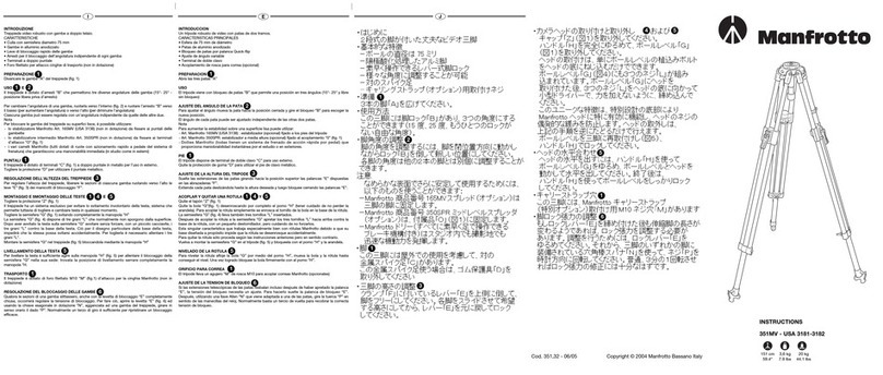
  9. Manfrotto 132 User manual

Manfrotto 132 User manual

J
E
I
INTRODUCCION
Trípode de video ideal para exteriores
CARACTERISTICAS
• Patas de aluminio anodizado con secciones de acero
• Bloqueos para el ángulo de expansión
• Tirantes mediante cadena
• Bola para nivelar la cámara
PREPARATION
Abra las 3 patas "A"
USO
El trípode viene equipado con bloqueos "B" que limitan la expansión hasta un ángulo
de 30° respecto a la posición cerrada.
AJUSTE DEL ANGULO DE EXPANSION
Una vez abiertas las patas según se ha descrito arriba tendrá que mover la pata hacia
la posición de cerrado y girar el bloqueo "B" hasta que escuche un "clic" (posición
LIBRE). El ángulo de cada pata puede ajustarse independientemente.
AJUSTE DEL LARGO DE LA CADENA Y
El trípode viene también con una cadena "C" que se fija a las abrazaderas "D".
Es para proveer el trípode de una mayor estabilidad cuando las patas se abren en
posición libre.
Es posible reducir o aumentar el largo de la cadena para modificar el ángulo de
expansión.
- Retire el clip de cadena "E" (fig. 3) y luego la cadena
- Reacople el clip de cadena "E" (fig. 4) a la abrazadera "D" después de haber
seleccionado el nuevo largo de la cadena.
Enganche la cadena en el lado recto del clip de cadena "E" entre los orificios
"G" y "H" de la abrazadera "D".
AJUSTE DE ALTURA DEL TRIPODE
Para liberar las secciones de las patas afloje las palomillas "L" en las abrazaderas
"D", tire hacia fuera hasta el largo deseado y luego vuelva a apretar las palomillas "L"
ACOPLAR Y QUITAR UNA ROTULA Y
Quite el tapón "Z" (fig. 1)
Quite la bola "M" (fig. 1) desenroscando por completo el pomo "N" (tener cuidado de
no perder la arandela).
Para acoplar la rótula simplemente se enrosca el tornillo de la bola en la base de la
rótula.
La semiesfera "M" (fig. 5) lleva también tres tornillos "P" insertados.
Despues de acoplar la rótula a la semiesfera "M" apretar los tres tornillos “P" hacia
arriba contra la base de la rótula, con un pequeño destornillador, pero cuidando de
no forzarlos.
Esta singular característica que trabaja especialmente bien con rótulas Manfrotto
debido a que su base diseñada a propósito impide que la rótula se desenrosque
accidentalmente.
Para quitar la rótula sólo proceda según las instrucciones anteriores pero en sentido
contrario.
Vuelva a montar la semiesfera "M" en el trípode (fig. 6) y bloqueela con el pomo "N" y
la arandela.
NIVELADO DE LA ROTULA
Para nivelar la rótula afloje la bola "M" por medio del pomo "N", mueva la bola y la
rótula hasta conseguir el nivel. Una vez logrado bloquee la bola firmemente con el
pomo "N".
INTRODUZIONE
Treppiedi cine/video ideale per esterni.
CARATTERISTICHE
• Gambe in alluminio anodizzato ed acciaio
• Arresti per bloccaggio dell’angolatura indipendente di ogni gamba
• Catena per apertura regolabile delle gambe
• Sfera per il livellamento della testa
PRAPARAZIONE
Divaricare le gambe “A” del treppiede (fig. 1).
USO E
Il treppiede è dotato di arresti “B” che permettono una posizione fissa di lavoro a 30°
e una libera.
Per liberare la posizione della gamba, spostarla verso l’interno (fig. 2) e ruotare
l’arresto “B”, posto alla sommità dei manicotti di ancoraggio, fino allo scatto
(posizione “FREE”).
Ciascuna gamba può essere regolata con un’angolatura indipendente da quelle delle
altre due.
Il treppiede è inoltre dotato di catena “C”, fissata ai manicotti “D”, per il bloccaggio
dell’angolazione delle gambe qualora si escludano gli arresti “B”.
E’ possibile accorciare o allungare la lunghezza della catena per variare l’angolazione
delle gambe:
- estrarre la coppiglia “E” (fig. 3) per togliere la catena
- rimontare la coppiglia “E” (fig. 4) nel manicotto “D” dopo aver scelto la nuova
lunghezza della catena “C”
Agganciare la catena sull’estremità dritta della coppiglia “E” tra i due fori “G” e
“H” del manicotto “D”
REGOLAZIONE DELL’ALTEZZA DEL TREPPIEDE
Regolare l’altezza del treppiede: liberare le sezioni di ciascuna gamba svitando le
manopole “L” dei manicotti di bloccaggio “D”.
MONTAGGIO E SMONTAGGIO DELLE TESTE E
Togliere la protezione “Z” (fig. 1)
Il treppiede ha un sistema esclusivo per evitare lo svitamento involontario della testa,
sistema che permette tuttavia di togliere e cambiare testa in qualsiasi momento.
Togliere la semisfera “M” (fig. 1), svitando completamente la manopola “N” (attenzione
a non perdere la rondella).
La semisfera “M” (fig. 5) dispone di tre grani “P” che normalmente non sporgono
dalla superficie. Dopo aver avvitato la testa sulla semisfera “M” avvitare senza
forzare, con un piccolo cacciavite, i tre grani “P” contro la base della testa. Ciò per il
disegno particolare della base della testa, impedirà che la stessa possa svitarsi
accidentalmente. Per toglierla è necessario allentare i tre grani “P”.
Montare la semisfera “M” nel treppiede (fig. 6), bloccandola mediante la manopola
“N” e la relativa rondella.
LIVELLAMENTO DELLA TESTA
Per livellare la testa è sufficiente agire sulla manopola “N” (fig. 6) per allentare il
bloccaggio della semisfera “M” nella sua sede: trovata la posizione di livellamento
serrare completamente la manopola “N”.
Cod. 132,47 - 09/04 Copyright © 2004 Manfrotto Bassano Italy 148 cm 6,9 kg 30 kg
58 1/4” 15.2 lbs 66.1 lbs
INSTRUCTIONS
132-132X - USA 3061
1
2
15 6
6
3 4
1
2
1
1
5 6
6
3 4
GB FD
INTRODUCTION
Trépied vidéo, idèal pour une utilisation en extérieur.
CARACTERISTIQUES
• Jambes supérieures en aluminium anodisé avec extentions en acier.
• Réglage de l’angle d’écartement des jambes.
• Chaîne de sécurité.
• Boule niveleuse pour caméra.
PREPARATION
Ouvrez les 3 jambes “A”.
L’angle d’écartement des jambes se bloque grâce au bouton de blocage “B”, le
limitant à 30° par rapport à la position fermée.
MODE D’UTILISATION
REGLAGE DE L’ANGLE D’ECARTEMENT
Une fois les jambes ouvertes, comme indiqué ci dessus, si vous avez besoin de régler
l’écartement, vous devrez ramener les jambes dans la position fermée et tourner le
bouton “B” jusqu’à ce que vous entediez un “click”(position “FREE”).
L’angle de chaque jambe peut etre réglé indépendamment.
REGLAGE DELA LONGUEUR DE LA CHAINE ET
Le trépied est toujours livré avec une chaîne “C” montée sur la fonderie “D” pour
permettre au trépied d’avoir, lorsque les jambes sont en position libre, une meilleure
stabilité.
Il est possible d’augmenter ou de réduire la longueur de la chaîne pour modifier
l’angle d’écartement des jambes.
- Retirez le clip de la chaîne “E” (fig. 3) et ensuite la chaîne.
- Remettez le clip de la chaîne “E” (fig. 4) sur la fonderie “D” après avoir déterminé la
nouvelle longueur de la chaîne.
Passez la chaîne sur le côté droit du clip “E” entre les deux fixations “G” et “H” de
la fonderie “D”.
REGLADE DE LA HAUTEUR DU TREPIED
Pour libérer les sections des jambes, dévissez les boutons “L” des fonderies “D”,
réglez les sections aux longueurs souhaitées puis resserrez les boutons “L”.
MONTAGE ET DEMONTAGE DE LA ROTULE ET
Retirez l’embout en caoutchouc “Z” (fig. 1).
Retirez la demic sphère “M” (fig. 1) en dévissant complètement la poignée “N”
(attention de ne pas perdre la bague).
Pour monter votre rotule, il vous suffit simplement de visser la demie sphère dans le
filetage de la rotule réservé à cet effet.
La demie sphère “M” (fig. 5) est munie de 3 vis sans tête “P”.
Une fois la rotule montée sur la demie sphère, vissez les vis sans tête avec un petit
tournevis jusqu’à ce qu’elles viennent en butée sur la base de la rotule, faites
attention de ne pas les forcer.
Cette caractéristique unique, conçue spécialement pour les rotules Manfrotto, (leur
base ayant une forme particulière adaptée à ce système), permet d’éviter un
desserrage accidentel de la tête.
Pour retirer la rotule, suivez tout simplement les instructions ci dessus dans le sens
inverse.
Remontez la demie sphère “M” sur le trépied (fig. 6), et bloquez la avec la poignée
“N” et la bague.
MISE A NIVEAU DE LA ROTULE
Pour mettre à niveau la rotule, desserrez la demie sphère “M” en utilisant la poignée
“N”, bougez la boule et la rotule jusqu’à l’obtention de la mise à niveau.
Une fois obtenue, bloquez la boule fermement avec la poignée “N”.
INTRODUCTION
Video tripod ideal for external use.
KEY FEATURES
• Anodised aluminium legs with steel extensions
• Angle leg locks
• Chain brace
• Ball for camera levelling
SET UP
Open the 3 legs "A"
The tripod is provided with leg locks "B" which limit the spread to a 30° angle from
the closed position.
USE
LEG ANGLE ADJUSTMENT
Having opened the legs as above you will need to move a leg back towards the
closed position and rotate the lock "B" until you hear a "click" (position "FREE")
The angle of each leg can be adjusted independently.
CHAIN LENGTH ADJUSTMENT &
The tripod is also provided with a chain "C" which is fixed onto the clamps "D".
This is to give the tripod stability when in use with the legs in the free position.
It is possible to reduce or increase the length of the chain to modify the angle of the
legs:
- Remove the chain clip "E" (fig. 3) and then the chain
- Reassemble the chain clip "E" (fig. 4) on the clamps "D" after choosing the new
length of the chain
Hook the chain on the straight edge of the chain clips "E" between holes "G"
and "H" of the clamp "D".
TRIPOD HEIGHT ADJUSTMENT
To release the extensions of the legs, unscrew the knobs "L" on the clamps "D" pull
out to desired length and then retighten the locking knobs "L".
MOUNTING AND REMOVING A CAMERA HEAD &
Remove the cap "Z" (fig. 1).
Remove the half ball "M" (fig. 1), by unscrewing completely the handle "N" (taking
care not lose the washer). To mount your head simply screw the ball stud into the
base of your head.
The half ball "M" (fig. 5) also has three screws "P" set in the ball. After mounting head
on the half ball "M", tighten the three set screws “P” up against the base of the head,
with a small screwdriver, taking care not to force them.
This unique feature, which works especially well with Manfrotto heads due to their
specially designed base, prevents the head unscrewing accidentally. To remove the
head, simply follow the above instructions in reverse.
Re mount the half ball "M" on the tripod (fig. 6), and lock it with handle "N" and the
washer.
HEAD LEVELLING
To level the head, loosen the half ball “M” using the handle "N" move the ball and
head until a level has been achieved. Once this has been done, lock the ball firmly
using the handle "N".
EINFÜHRUNG
Videostativ für den Einsatz im Freien.
AUSSTATTUNGSMERKMALE
• Aluminiumbeine mit Stahlauszügen
• Arretierung für Beinanstellwinkel
• Ketten-Stabilisator
• Nivellierpfanne
AUFSTELLEN
Öffnen Sie die drei Beine "A".
GEBRAUCH
BEINANSTELLWINKEL
Das Stativ ist mit Arretierungen für einen Beinanstellwinkel "B" von 0 - 30°
ausgerüstet.
Um die Arretierung für den Beinanstellwinkel zu lösen, müssen Sie zuerst das
entsprechende Bein gegen die Mitte zurückschwenken. Drehen Sie nun die
Arretierung "B" bis diese einklinkt. Nun ist die frei variierbare Position eingestellt.
Für jedes Bein kann der Anstellwinkel individuell eingestellt werden.
VERSTELLUNG DER KETTENLÄNGE UND
Das Stativ ist mit einer Kette "C" ausgerüstet, welche an den Halterungen "D"
befestigt ist. Die Kette bietet zusätzliche Stabilität, wenn das Stativ mit frei variablem
Beinanstellwinkel eingesetzt wird.
Um die Länge der Kette zu verändern, gehen Sie wie folgt vor:
- Entfernen Sie die Kettensicherung "E" (fig. 3) und danach die Kette.
- Wählen Sie die neue Länge und hängen Sie die Kettensicherung wieder in die
Halterung "D" (fig. 4).
Befestigen Sie die Kette auf der geraden Achse der Kettensicherung "E" und
zwischen den Löchern "G" und "H" welche sich in der Halterung "D" befinden.
HÖHENVERSTELLUNG DES STATIVS
Um die Länge des Beines zu verstellen, lösen Sie die Schraube "L" welche an der
Muffe "D" angebracht ist. Schieben Sie den Auszug in die gewünschte Position und
ziehen Sie die Schraube "L" wieder gut an.
BEFESTIGEN UND ENTFERNEN EINES KAMERAKOPFES UND
Entfernen Sie die Schutzkappe "Z" (fig. 1). Entfernen Sie die Nivellier-Halbkugel "M"
(fig. 1), indem Sie die Schraube "N" komplett entfernen. Achten Sie darauf, die
Unterlagsscheibe nicht zu verlieren. Drehen Sie nun die Nivellier-Halbkugel in Ihren
Kamerakopf.
Ziehen Sie die drei Schrauben "P" auf der Unterseite der Nivellier-Halbkugel "M" (fig.
5) mit einem kleinen Schraubenzieher an. Drehen Sie die Schrauben mit geringem
Kraftaufwand gegen die Unterseite des Kamerakopfes. Diese Blockierung
funktioniert vor allem mit Manfrotto Neigeköpfen sehr gut, da diese mit einer
speziellen Unterseite ausgerüstet sind, welche ein Losdrehen des Kopfes verhindert.
Möchten Sie den Kopf wieder von der Nivellier-Halbkugel nehmen, so lösen Sie
zuerst die drei Schrauben “P”, bevor Sie den Kopf abschrauben.
Setzen Sie nun die Nivellier-Halbkugel "M" zusammen mit dem aufgeschraubten
Kopf auf das Stativ (fig. 6) und befestigen Sie die Schraube "N" zusammen mit der
Unterlagsscheibe.
AUSNIVELLIEREN DES KAMERAKOPFES
Um den Kamerakopf auszunivellieren, lösen Sie die Halbkugel "M", indem Sie die
Schraube "N" öffnen. Bringen Sie nun den Kamerakopf in die gewünschte Position
und ziehen Sie die Schraube "N" wieder gut an.
Z
M
BN
C
M
N
D
G
E
H
A
C
L
D
B
A
E
2
1
P
M
4
632
1
5
1
2
1
5 6
6
3 4
1
2
1
5 6
6
3 4
1
2
1
5 6
6
3 4
This manual suits for next models

1

Other Manfrotto Camera Accessories manuals

Manfrotto MVG300XM User manual

Manfrotto

Manfrotto MVG300XM User manual

Manfrotto 488RC0 User manual

Manfrotto

Manfrotto 488RC0 User manual

Manfrotto 718B User manual

Manfrotto

Manfrotto 718B User manual

Manfrotto MKCOMPACTACN-BK User manual

Manfrotto

Manfrotto MKCOMPACTACN-BK User manual

Manfrotto 553 User manual

Manfrotto

Manfrotto 553 User manual

Manfrotto 131D User manual

Manfrotto

Manfrotto 131D User manual

Manfrotto Joby Pixi Plus User manual

Manfrotto

Manfrotto Joby Pixi Plus User manual

Manfrotto MVG220 User manual

Manfrotto

Manfrotto MVG220 User manual

Manfrotto 482 User manual

Manfrotto

Manfrotto 482 User manual

Manfrotto 7302YB User manual

Manfrotto

Manfrotto 7302YB User manual

Manfrotto Lumimuse User manual

Manfrotto

Manfrotto Lumimuse User manual

Manfrotto 745MF3 User manual

Manfrotto

Manfrotto 745MF3 User manual

Manfrotto 562B User manual

Manfrotto

Manfrotto 562B User manual

Manfrotto Lastolite Ezybalance User manual

Manfrotto

Manfrotto Lastolite Ezybalance User manual

Manfrotto 482LCD User manual

Manfrotto

Manfrotto 482LCD User manual

Manfrotto MKCOMPACTACN-BK User manual

Manfrotto

Manfrotto MKCOMPACTACN-BK User manual

Manfrotto 341 User manual

Manfrotto

Manfrotto 341 User manual

Manfrotto 545B User manual

Manfrotto

Manfrotto 545B User manual

Manfrotto C350N User manual

Manfrotto

Manfrotto C350N User manual

Manfrotto MT190GOA4 User manual

Manfrotto

Manfrotto MT190GOA4 User manual

Manfrotto 055BWB User manual

Manfrotto

Manfrotto 055BWB User manual

Manfrotto MVG220 User manual

Manfrotto

Manfrotto MVG220 User manual

Manfrotto 503HDV User manual

Manfrotto

Manfrotto 503HDV User manual

Manfrotto MVMFXPRO2W User manual

Manfrotto

Manfrotto MVMFXPRO2W User manual

Popular Camera Accessories manuals by other brands

Z&X PRECISE P1 user guide

Z&X

Z&X PRECISE P1 user guide

Redarc BMS1230S2 manual

Redarc

Redarc BMS1230S2 manual

edelkrone WING PRO user manual

edelkrone

edelkrone WING PRO user manual

Sunpak 6600PG owner's manual

Sunpak

Sunpak 6600PG owner's manual

Panasonic HX025 operating instructions

Panasonic

Panasonic HX025 operating instructions

Rohde & Schwarz TSMA6 Series Getting started

Rohde & Schwarz

Rohde & Schwarz TSMA6 Series Getting started

Vinten vector 430 Operator's guide

Vinten

Vinten vector 430 Operator's guide

Yongnuo YN650EX-RF manual

Yongnuo

Yongnuo YN650EX-RF manual

Strategic Victa ACC1600 user manual

Strategic Victa

Strategic Victa ACC1600 user manual

Ambient TinyLockit ACN-TL manual

Ambient

Ambient TinyLockit ACN-TL manual

Hohem iSteadyPro 4 user manual

Hohem

Hohem iSteadyPro 4 user manual

Nikon 1 NIKKOR VR 6.7-13mm f/3.5-5.6 user manual

Nikon

Nikon 1 NIKKOR VR 6.7-13mm f/3.5-5.6 user manual

Norman P808-1200 instruction manual

Norman

Norman P808-1200 instruction manual

Hoppecke grid aquagen pro Assembly and operating manual

Hoppecke

Hoppecke grid aquagen pro Assembly and operating manual

Weed Eater WE20VRB instruction manual

Weed Eater

Weed Eater WE20VRB instruction manual

iFootage Seastars Q1S user manual

iFootage

iFootage Seastars Q1S user manual

ACDelco PowerSports instructions

ACDelco

ACDelco PowerSports instructions

Conrad 779481 operating instructions

Conrad

Conrad 779481 operating instructions

manuals.online logo
manuals.online logoBrands
  • About & Mission
  • Contact us
  • Privacy Policy
  • Terms and Conditions

Copyright 2025 Manuals.Online. All Rights Reserved.