-2-
A. Description
1. Function
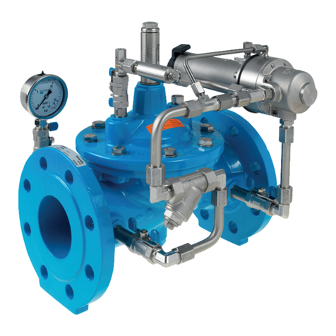
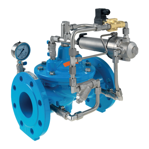
The valve maintains a constant pre-set inlet pressure (p1) and opens and closes to keep a minimal water
level in a basin. Depending on the settings it can work as a pressure relief valve. Then any excess of the
system pressure is relieved by fast opening of the valve.
The closing procedure is slow in order to avoid shock pressure loads. Flow rates have no effect on the
maintained pressure which is regulated by the control valve. The overpressure or maintained pressure of the
standard version can be set within the range of 1.5 bar to 12 bar.
Technical features:
Medium: Drinking water
Pressure stages: PN 10 (Standard DN 200 and upwards)
PN 16 (Standard up to and including DN 150)
PN 25
Flanges: Connection dimensions acc. DIN EN 1092 –2
Manometer: EN 837-1, accuracy class 1.6
Main valve material: GGG 40
Temperature range: 2 to 40º C
2. General safety guidelines
The Hawle HAWIDO regulating valve is designed for use in drinking water supply systems. Please consult
the manufacturer before using it with other media.
Material damage or injury to persons can occur if the HAWIDO is not installed, commissioned, operated or
maintained according to these instructions or to codes of practice.
As a precondition, it is assumed that all technical regulations (e.g. SVGW, ÖVGW, DVGW...), codes of
practice (e.g. VDE, VDI ...), laws and standards are understood, and will be adhered to and applied.
Work on electrical installations (e.g. installation of magnetic position switches, solenoid valves, etc.) may only
be carried out by personnel authorised to carry out this work.
The responsibility for layout, installation position and commissioning of the fittings in the pipe work lies with
the designer, installer and/or user. Design or installation errors can adversely affect the operation of the
regulating valve and can create a significant risk. If in doubt, please consult us.


