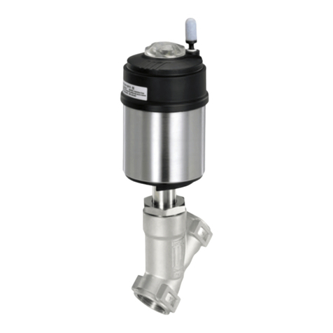
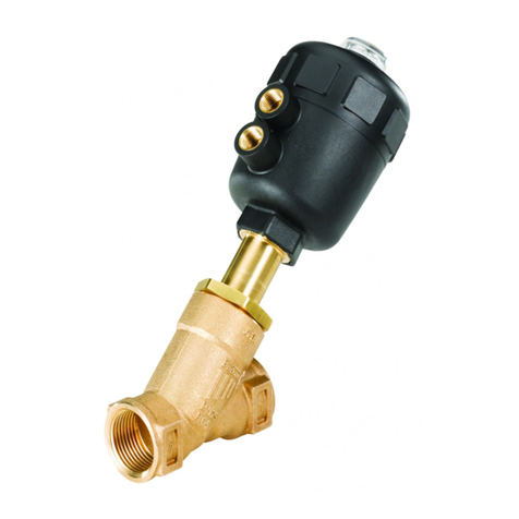
Burkert 3360 User manual

Service Manual
Type 3360, 3361, AE3360, AE3361
Electromotive control valve

We reserve the right to make technical changes without notice.
Technische Änderungen vorbehalten.
Sous réserve de modifications techniques.
© Bürkert Werke GmbH & Co. KG, 2015 - 2019
Service Manual 1903/02_EU-EN_00810485 / Original DE

3
Content
1 THE SERVICE INSTRUCTIONS ....................................................................................................................................................6
1.1 Symbols ......................................................................................................................................................................................6
1.2 Definitions of terms ..............................................................................................................................................................6
2 BASIC SAFETY INSTRUCTIONS .................................................................................................................................................7
3 GENERAL INFORMATION ................................................................................................................................................................9
3.1 Contact addresses ................................................................................................................................................................9
3.2 Warranty ......................................................................................................................................................................................9
3.3 Information on the Internet ...............................................................................................................................................9
3.4 Auxiliary materials .................................................................................................................................................................9
4 OVERVIEW OF SPARE PARTS ...................................................................................................................................................10
4.1 Replacement part sets for Type 3360 ......................................................................................................................10
4.2 Replacement part sets for Type 3361 ......................................................................................................................11
4.3 Spare parts for Types 3360 and 3361 .....................................................................................................................12
5 REPLACING THE CONTROL CONE ........................................................................................................................................13
5.1 Required work steps .........................................................................................................................................................13
5.2 Required tools and equipment ....................................................................................................................................13
5.3 Replace control cone ........................................................................................................................................................14
6 REPLACING THE SEAL SET .......................................................................................................................................................16
6.1 Required work steps .........................................................................................................................................................16
6.2 Required tools and equipment ....................................................................................................................................16
6.3 Remove control cone ........................................................................................................................................................17
6.4 Replace packing gland, sizes DN 10 – DN 15, seat sizes 3 – 10 or vacuum version ...................18
6.5 Replace packing gland, sizes DN 20 – DN 50, seat sizes 20 – 50 ..........................................................20
6.6 Mount control cone ............................................................................................................................................................22
7 REPLACING THE VALVE SEAT ..................................................................................................................................................23
7.1 Required work steps .........................................................................................................................................................23
7.2 Required tools and equipment ....................................................................................................................................23
7.3 Replace valve seat .............................................................................................................................................................24
Type 3360, 3361
english

4
Type 3360, 3361
8 SETTING OPERATING STATE ....................................................................................................................................................26
8.1 Setting operating state for devices without display module ......................................................................26
8.2 Setting operating state for devices with display module ..............................................................................27
9 MANUAL ACTUATION OF THE VALVE ..................................................................................................................................28
9.1 Electrically actuating valve for devices without display module ...............................................................28
9.2 Electrically actuating valve for devices without display module ...............................................................29
9.3 Mechanical actuation of the valve .............................................................................................................................30
9.3.1 Required work steps ..........................................................................................................................30
9.3.2 Required tool .......................................................................................................................................30
9.3.3 Removing dummy cover or display module ..................................................................................31
9.3.4 Removing the fieldbus gateway from the actuator .....................................................................31
9.3.5 Actuating valve mechanically ...........................................................................................................32
9.3.6 Mounting the fieldbus gateway on the actuator ..........................................................................33
9.3.7 Closing the dummy cover or display module ...............................................................................34
10 REMOVING OF THE ACTUATOR ..............................................................................................................................................35
10.1 Required work steps .........................................................................................................................................................35
10.2 Required tools ......................................................................................................................................................................35
10.3 Remove actuator from valve body .............................................................................................................................35
11 MOUNTING ACTUATOR ON VALVE BODY ..........................................................................................................................37
12 ADJUSTING THE POSITION CONTROL – RUNNING X.TUNE..................................................................................39
12.1 Adjustment the position control using the buttons in the device ............................................................39
12.2 Adjustment position control on the PC or display of the device ..............................................................40
13 REPLACEMENT OF THE ENERGY PACK .............................................................................................................................41
13.1 Required work steps .........................................................................................................................................................41
13.2 Required tools and equipment ....................................................................................................................................41
13.3 Opening the actuator housing for device without fieldbus gateway ......................................................42
13.4 Opening the actuator housing for device with fieldbus gateway .............................................................44
13.5 Replacing the SAFEPOS energy-pack ....................................................................................................................46
13.6 Closing the actuator housing for device without fieldbus gateway ........................................................47
13.7 Closing the actuator housing for device with fieldbus gateway ...............................................................49
english

5
Type 3360, 3361
14 ACCESSORIES, SPARE PARTS ................................................................................................................................................51
14.1 Communications software .............................................................................................................................................52
14.1.1 USB interface ......................................................................................................................................52
14.2 Spare parts .............................................................................................................................................................................53
14.2.1 Spare parts for control valves of Types 3360 and 3361 ..........................................................53
14.2.2 Spare parts for angle seat control valve of Type 3360..............................................................53
14.2.3 Spare parts for globe control valve of Type 3361 ......................................................................53
14.3 Installation tools ..................................................................................................................................................................55
14.3.1 Installation tools for control valves of Types 3360 and 3361 ..................................................55
14.3.2 Installation tools for control valves of Type 3361 ........................................................................55
15 PACKAGING, TRANSPORT ..........................................................................................................................................................56
16 STORAGE ..............................................................................................................................................................................................56
17 DISPOSAL ............................................................................................................................................................................................56
english

6
The service instructions
Type 3360, 3361
1 THE SERVICE INSTRUCTIONS
The service instructions describe the procedure for replacing spare parts of the process valves of Types 3360 and
3361.
Keep these instructions in a location which is easily accessible to every user and make these instructions available
to every new owner of the device.
The service instructions contain important safety information.
Failure to observe these instructions may result in hazardous situations.
▶The service instructions must be read and understood.
1.1 Symbols
DANGER!
Warns of an immediate danger!
▶Failure to observe the warning will result in fatal or serious injuries.
WARNING!
Warns of a potentially dangerous situation!
▶Failure to observe the warning may result in serious injuries or death.
CAUTION!
Warns of a possible danger!
▶Failure to observe this warning may result in a moderate or minor injury.
ATTENTION!
Warns of damage to property!
• Failure to observe the warning may result in damage to the device or other equipment.
Indicates important additional information, tips and recommendations.
Refers to information in these operating instructions or in other documentation.
▶designates an instruction which you must follow to prevent a hazard.
→designates a procedure which you must carry out.
1.2 Definitions of terms
• The term "device" used in these instructions applies to all valve types described in these instructions:
Type 3360, electromotive angle seat control valve
Type 3361, electromotive globe control valve
english

7
Basic safety instructions
Type 3360, 3361
2 BASIC SAFETY INSTRUCTIONS
These safety instructions do not make allowance for any
• contingencies and events which may arise during the assembly, operation, and maintenance.
• local safety regulations – the operator is responsible for observing these regulations, also in relation to the instal-
lation personnel.
Risk of injury from high pressure.
▶Before working on the system or device, switch off the pressure and vent or drain lines.
Danger of burns and risk of fire.
Following an extended duty cycle or as a result of a hot medium, the surface of the device may become hot.
▶Only touch the device when wearing protective gloves.
▶Keep the device away from highly flammable substances and media.
Danger due to loud noises.
▶Depending on the operating conditions, the device may generate loud noises. More detailed information on the likeli-
hood of loud noises is available from the relevant sales office.
▶Wear hearing protection when in the vicinity of the device.
Leaking medium when the packing gland is worn.
▶Regularly check relief bore for leaking medium.
▶If medium is leaking out of the relief bore, replace the packing gland.
▶If the media is hazardous, protect the area surrounding the discharge point against dangers.
Risk of crushing due to mechanically moving parts.
▶Perform installation and maintenance work only in the isolated state.
Devices with SAFEPOS energy-pack: Completely drain SAFEPOS energy-pack. Wait until LED illuminated ring
goes out; the LED status must not be in LED off mode.
▶Keep clear of the openings in the valve body.
Danger due to an uncontrolled process in the event of a power failure.
If devices do not have the optional SAFEPOS energy-pack, the valve remains in an undefined position in the event of
a power failure.
▶If the valve position is relevant as regards safety in the event of a power failure: Use only those devices which have
the SAFEPOS energy-pack (optional energy pack).
▶In the SAFEPOS select a valve position which is safe for the process.
english

8
Basic safety instructions
Type 3360, 3361
General hazardous situations.
To prevent injuries:
▶Transport, install and dismantle a heavy device with the help of another person and with appropriate tools.
▶Only trained technicians may perform installation and maintenance work.
▶Secure to prevent unintentional actuation.
▶Do not make any internal or external changes on the device and do not subject it to mechanical stress.
▶Only feed media specified in the data sheet into the media connections.
▶The valves must be installed in accordance with the regulations applicable in the country.
▶After an interruption in the power supply, ensure that the process is restarted in a controlled manner. Observe
sequence!
1. Apply supply voltage.
2. Charge the device with medium.
▶Observe the general rules of technology.
▶Install the valves must in accordance with the regulations applicable in the country.
NOTE!
Electrostatically sensitive components and modules.
The device contains electronic components which react sensitively to electrostatic discharge (ESD). Contact with
electrostatically charged persons or objects are hazardous to these components. In the worst case scenario, they
will be destroyed immediately or will fail after start-up.
• Observe the requirements in accordance with EN 61340-5-1 to minimize or avoid the possibility of damage
caused by a sudden electrostatic discharge.
• Do not touch electronic components while the supply voltage is switched on.
english

9
General information
Type 3360, 3361
3 GENERAL INFORMATION
3.1 Contact addresses
Germany
Bürkert Fluid Control Systems
Sales Center
Christian-Bürkert-Str. 13-17
D-74653 Ingelfingen
Tel. + 49 (0) 7940 - 10 91 111
Fax + 49 (0) 7940 - 10 91 448
Email: [email protected]
International
Contact addresses can be found on the final pages of the printed operating instructions.
And also on the Internet at:
www.burkert.com
3.2 Warranty
The warranty is only valid if the device is used as intended in accordance with the specified application conditions.
3.3 Information on the Internet
Operating instructions and data sheets for Types 3360 and 3361 can be found on the Internet at:
www.burkert.com
3.4 Auxiliary materials
The following auxiliary materials are recommended in these instructions for carrying out repairs:
Type of auxiliary material Auxiliary material Manufacturer's specifications
Sealer and anti-seize agents Silicone grease OKS 1110-3 OKS Schmierstoffe GmbH
www.oks-germany.com
Lubricant Klüberpaste UH1 96-402 Klüber Lubrication München
www.klueber.de
english

10
Overview of spare parts
Type 3360, 3361
4 OVERVIEW OF SPARE PARTS
4.1 Replacement part sets for Type 3360
The following replacement part sets are available for Type 3360:
• Control cone set
consisting of: Control cone, dowel pin, graphite seal and lubricant
• Seal set for the packing gland
consisting of: Individual parts of the packing gland, graphite seal and lubricant
• Spindle guide for the packing gland
consisting of: Spindle guide, graphite seal and lubricant
5
2
1
4
Item Description
1 Packing gland
2 Control cone with dowel pin
4 Spindle guide
5 Graphite seal
Table 1: Spare parts Type 3360
english

11
Overview of spare parts
Type 3360, 3361
4.2 Replacement part sets for Type 3361
The following replacement part sets are available for Type 3361:
• Control cone set
consisting of: Control cone, dowel pin, graphite seal and lubricant
• Valve seat set
consisting of: Valve seat and graphite seal and (with O-ring from seat size 25)
• Seal set for the packing gland
consisting of: Individual parts of the packing gland, graphite seal and lubricant
• Spindle guide for the packing gland
consisting of: Spindle guide, graphite seal and lubricant
5
2
3
4
1
Item Description
1 Packing gland
2 Control cone with dowel pin
3 Valve seat (with O-ring from seat size 25)
4 Spindle guide
5 Graphite seal
Table 2: Spare parts Type 3361
english

12
Overview of spare parts
Type 3360, 3361
4.3 Spare parts for Types 3360 and 3361
• SAFEPOS energy-pack.
Optionally there is an energy pack for the device. If the supply voltage fails, the energy pack supplies the
actuator with the required energy to move the valve into the required position which can be adjusted via the
menu.
SAFEPOS
energy-pack
english

13
Replacing the control cone
Type 3360, 3361
5 REPLACING THE CONTROL CONE
DANGER!
Risk of injury from high pressure.
▶Before working on the system or device, switch off the pressure and vent or drain lines.
WARNING!
Risk of injury due to improper replacement of spare parts.
▶Spare parts may be replaced only by trained technicians and with the appropriate tools.
Risk of crushing
If electrically connected devices are not installed in the pipeline, there is a risk of crushing by mechanically
moving parts.
▶Do not reach into the openings of the valve body.
5.1 Required work steps
The following steps are required to change the control cone.
1. Set operating state MANUAL, chapter "8" on page 26.
2. Move valve into open position., chapter "9" on page 28.
3. Switch off the supply voltage. Wait until LED illuminated ring goes out.
4. Remove actuator from valve body, chapter "10" on page 35.
5. Replace control cone, chapter "5.3" on page 14.
6. Mount actuator on valve body, chapter "11" on page 37.
7. Apply supply voltage.
8. Adjusting the position control – running X.TUNE, chapter "12" on page 39.
9. Set operting state AUTOMATIK, chapter "8" on page 26.
5.2 Required tools and equipment
• Allen key, width across flats 3 mm
Only required when no supply voltage is applied to the device in order to move the valve into the open position.
• Open-end wrench
• Holding device to clamp the valve body
• Pin punch
• Hammer
• Prism to support the control cone
• Suitable lubricant, e.g. Klüberpaste UH1 96-402 of the company Klüber.
english

14
Replacing the control cone
Type 3360, 3361
WARNING!
Risk of injury if the wrong tools are used.
It is dangerous to use unsuitable tools for installation work as the device may be damaged.
▶Work on the device only with tools which are specified for the particular activity.
5.3 Replace control cone
Preconditions: MANUAL operating state, valve position at least 1/3 open, supply voltage switched off,
actuator removed from the valve body.
Control cone
Graphite seal
Dowel pin
Spindle
Sectional view:
Figure 1: Replace control cone
Remove control cone:
→Knock out dowel pin using a suitable pin punch (see table).
Spindle diameter
[mm]
Pin punch Orifice connection
(valve body) [DN]
10 4 10/15 and 20
14 5 25 to 50
Table 3: Spindle diameter with reference to DN
→Remove control cone.
Mount new control cone:
NOTE!
Important information for the problem-free and safe functioning of the device: The sealing surface and cone
contour of the control cone must not be damaged.
→Attach new control cone to the spindle.
→Align bores of the control cone and spindle.
english

15
Replacing the control cone
Type 3360, 3361
→Support control cone on the cylindrical part with the help of a prism.
→Put on dowel pin and carefully knock in with a hammer.
→Position the dowel pin in the center of the spindle axis.
Next steps:
• Mount actuator on valve body, chapter "11" on page 37.
• Apply supply voltage.
• Adjusting the position control – running X.TUNE, chapter "12" on page 39.
• Set operting state AUTOMATIK, chapter "8" on page 26.
english
16
Replacing the seal set
Type 3360, 3361
6 REPLACING THE SEAL SET
DANGER!
Risk of injury from high pressure.
▶Before working on the system or device, switch off the pressure and vent or drain lines.
WARNING!
Risk of injury due to improper replacement of spare parts.
▶Spare parts may be replaced only by trained technicians and with the appropriate tools.
6.1 Required work steps
1. Set operating state MANUAL, chapter "8" on page 26.
2. Move valve into open position., chapter "9" on page 28.
3. Switch off the supply voltage. Wait until LED illuminated ring goes out.
4. Remove actuator from valve body, chapter "10" on page 35.
5. Remove control cone, chapter "6.3" on page 17.
6. Replace packing gland,
for sizes DN 10 – 15, seat size 3 – 10 or vacuum version, chapter "6.4" on page 18,
for sizes DN 20 – 50, seat size 20 – 50, chapter "6.5" on page 20
7. Mount control cone, chapter "6.6" on page 22.
8. Mount actuator on valve body, chapter "11" on page 37.
9. Apply supply voltage.
10. Adjusting the position control – running X.TUNE, chapter "12" on page 39.
11. Set operting state AUTOMATIK, chapter "8" on page 26.
6.2 Required tools and equipment
• Allen key, width across flats 3 mm
Only required when no supply voltage is applied to the device in order to move the valve into the open position.
• Open-end wrench
• Holding device to clamp the valve body
• Prism to support the control cone
• Pin punch
• Hammer
• Modified socket wrench. For valves from size DN 20, seat size 20 is required.
Order number see chapter "14.3.1 Installation tools for control valves of Types 3360 and 3361".
• Compressed air for removing the packing gland from DN 20 - 50, seat sizes 20 - 50.
• Suitable lubricant, e.g. Klüberpaste UH1 96-402 of the company Klüber.
english

17
Replacing the seal set
Type 3360, 3361
WARNING!
Risk of injury if the wrong tools are used.
It is dangerous to use unsuitable tools for installation work as the device may be damaged.
▶Work on the device only with tools which are specified for the particular activity.
6.3 Remove control cone
Preconditions: MANUAL operating state, valve position at least 1/3 open, supply voltage switched off,
actuator removed from the valve body.
Control cone
assembled
Dowel pin
Spindle
Sectional view:
Control cone
disassembled
Dowel pin
Figure 2: Remove control cone
→Knock out dowel pin using a suitable pin punch (see table).
Spindle diameter
[mm]
Pin punch Orifice connection
(valve body) [DN]
10 4 10/15 and 20
14 5 25 to 50
Table 4: Spindle diameter with reference to DN
→Remove control cone.
NOTE!
Important information for the problem-free and safe functioning of the device: The sealing surface and cone
contour of the control cone must not be damaged.
english

18
Replacing the seal set
Type 3360, 3361
6.4 Replace packing gland, sizes DN 10 – DN 15, seat
sizes 3 – 10 or vacuum version
Preconditions:
MANUAL operating state, valve position at least 1/3 open, supply voltage switched off, actuator removed
from the valve body, control cone removed.
Actuator base
Actuator housing
Screws (4)
Body connection
Figure 3: Dismantle actuator base
Dismantle actuator base:
→Clamp the body connection in a holding device.
→Loosen 4 screws on the actuator base.
→Remove actuator housing from the actuator base.
Remove packing gland:
Tool for pressing out the packing gland
package (example)
Packing gland
Upper spindle guide
Upper chevron seals
Upper thrust collar
Compression spring
Lower thrust collar
Lower chevron seals
Seal set for packing
gland:
Lower
spindle guide
Figure 4: Remove packing gland: Sizes DN 10 – DN 15, seat size 3 – 10 or vacuum version
english

19
Replacing the seal set
Type 3360, 3361
→Clamp the actuator base in a holding device.
→Unscrew lower spindle guide.
→Using a suitable tool (e.g. screwdriver), carefully press out the packing gland package.
Do not damage the upper spindle guide.
Mount new packing gland:
WARNING!
Danger if unsuitable lubricants are used.
Unsuitable lubricant may contaminate the medium. In oxygen applications there is a risk of an explosion.
▶Only use approved lubricants for specific applications, such as oxygen applications or analytical applications.
→Grease chevron seals of the new packing gland with the supplied lubricant.
Upper chevron seals
Pushing direction for
packing gland parts
Lower chevron seals
Upper thrust collar
Lower thrust collar
Compression spring
Figure 5: Construction of the packing gland
→Insert the parts of the new packing gland individually in the correct sequence (see "Figure 5").
→Grease spindle guide thread. Screw in spindle guide.
Observe tightening torque (see table).
Spindle diameter [mm]Orifice connection (valve body)
[DN] Tightening torques [Nm]
10 10/15 15
20 25
14 25 25
32 to 50 60
Table 5: Spindle guide tightening torques
→Place actuator base on the actuator housing.
→Tighten 4 screws crosswise.
Observe tightening torque of 5 Nm.
Next step:
• Mount control cone, chapter "6.6" on page 22.
english

20
Replacing the seal set
Type 3360, 3361
6.5 Replace packing gland, sizes DN 20 – DN 50,
seat sizes 20 – 50
Preconditions:
MANUAL operating state, valve position at least 1/3 open, supply voltage switched off, actuator removed
from the valve body, control cone removed.
Remove packing gland:
→Place the open-end wrench on the body connection. Unscrew spindle guide with the aid of a modified socket
wrench.
Modified socket wrench is not included in the spare part sets. The modified socket wrench can be
ordered separately. Order number see chapter "14 Accessories, spare parts". If you have any questions,
please contact your Bürkert sales office.
Spindle guide
Relief bore
Seal set for packing
gland:
Upper chevron
seals
Upper thrust collar
Compression
spring
Lower thrust collar
Lower chevron
seals
Packing gland
Figure 6: Replace packing gland: Sizes DN 20 – DN 50, seat sizes 20 – 50
WARNING!
Risk of injury from ejected parts.
When the spindle opening is exposed, the individual parts of the packing gland are pressed out at an undefined
speed when the relief bore is pressurized.
▶Before pressurizing with compressed air, safeguard the ambient area of the discharge opening (e.g. place
spindle on a firm base).
→Place spindle on a firm base.
→Pressurize relief bore with approx. 6 bar compressed air.
Caution!
Not all individual parts of the packing gland are pressed out by pressurizing with compressed air. Usually
the upper chevron seals remain in the packing gland tube. Replace the pressed out individual parts only.
english
Other manuals for 3360
5
This manual suits for next models
3
Table of contents
Other Burkert Control Unit manuals

Burkert
Burkert 6650 User manual

Burkert
Burkert 8791 REV.2 User manual

Burkert
Burkert 2060 User manual

Burkert
Burkert 2030 User manual

Burkert
Burkert 6144 User manual

Burkert
Burkert 8681 User manual

Burkert
Burkert 6213 User manual

Burkert
Burkert 0641 User manual

Burkert
Burkert 6518 User manual

Burkert
Burkert 7011 User manual

Burkert
Burkert 8681 User manual

Burkert
Burkert 6510 User manual

Burkert
Burkert 2035 User manual

Burkert
Burkert 8697 User manual

Burkert
Burkert 6518 User manual

Burkert
Burkert 2101 User manual

Burkert
Burkert 0127 User manual

Burkert
Burkert 8640 User manual

Burkert
Burkert 2103 Series User manual

Burkert
Burkert 2006 User manual