HAYASHI-REPIC LA-HDF5010RL User manual

Thank you for purchasing our product.
Prior to using it, please read the instruction manual thoroughly for
safe and correct operation.
Be sure to keep the instruction manual carefully at hand.
LED Light Source
Instruction Manual
LUMINAR ACE
Model LA-HDF5010RL
LA-HDF7010RL
HAYASHI-REPIC CO.,LTD.
0
2
4 6
8
LED ON REMOTE
LED OFF MANUAL
FINE
POWER
LED
TEMP.
ALARM
LIGHT CONTROL
10
E-1
Please use the light guide specifically provided for the product by manufacturer.
It may cause malfunction or insufficient performance of the product in case you use no light
guide or non-specified light guide.
CAUTION
Please use the AC power supply included.
When using something other than the included AC power supply,
please use the high-performance products more than accessory.
AC power supply cable must be properly grounded.
It may lead an accident or malfunction of the product if you do not make the proper ground.
CAUTION
Do not move while it is being illuminated.
Do not drop, or give a shock to the light source apparatus. (A trouble may result)
Do not disassemble or modify the light source apparatus. (A trouble may result.)
1. Accessories
CAUTION
Please carefully follow the instruction as misuse of the product may lead an accident of fire,
electric shock or malfunction of the product.
CAUTION
This LED light source is used for the illumination of image processing, microscope,
science observation.
Accessories
Options
Instruction Manual, Ethernet installation instructions,
Command manual, AC power supply(AC100V)
AC power supply:
US type (AC120V), UK type (AC240V), European type (AC230V)
Caution labels and statements provided in this manual are the description of potentially
hazardous situation which if not avoided could result in moderate or minor injury.
It could also advise safety precautions against unsafe practices.
CAUTION
CAUTION
E-2

Front Panel
Indicator
* LED ramp light is turn off.
Rear Panel
Power Switch (POWER)
This is a socket to introduce a light from the LED lamp built
in this apparatus to the light guide.
* Please Using Hayashi standard light guide.
・RS232C connector
2. Part Names
Control function change switch
・LAN port
This is a connector for external control. Please connect with a
function to be used.
Front switch [UP:REMOTE / DOWN:MANUAL]
* Regarding the switching of control function, please see to
[ 3. Operation method ].
Light quantity control knob (LIGHT CONTROL)
This knob is used when controlling brightness of the LED lamp
manually. A light quantity is increased by turning the knob in the
clockwise direction.
Light Guide Socket
POWER(Green):When the power ON, the light up.
・INPUT connector (REMOTE IN)
LED(Orange):When an abnormality occurs for LED ramp, the light up.
TEMP.(Red):When an abnormal temprature rise by inside the light box,
the light up.
Current adjustment volume (FINE)
For maintenance, so usually do not touch.
* Even LED is switched off, the cooling fan still remains to work as the main power supply is
active yet.
LED ON/LED OFF change switch
This function is enabled when the control function change switch is "MANUAL".
LED ON : LED ramp light is light up.
LED OFF : LED ramp light is turn off.
This switch is used to turn ON/OFF the power.
Control function change switch
・Rear switch 1 UP:SERIAL DOWN:STANDARD
・Rear switch 2 UP:LAN DOWN:RS232C
* Regarding the switching of control function, please see to
[ 3. Operation method ].
AC inlet
It is an AC power cord socket.
*When the input voltage is other than AC100V, please use another
power supply cord provided as an option.
0
2
4 6
8
LED ON REMOTE
LED OFF MANUAL
FINE
POWER
LED
TEMP.
ALARM
LIGHT CONTROL
10
SERIAL
L A NR S 2 3 2 C
STANDARD
L A N
AC100‑240V
R E M O T E I N
POWER
RS232C
21
ON
E-3
1) Insert the light guide in to the light guide socket of the apparatus.
2) Please insert the power supply into the AC inlet.
3) Switch the control function selector switch to the desired control function.
4) Insert the plug of the AC cord in the outlet. (Please take the ground)
5) Turn on the power switch.
6) Control the light quantity to your desired level to operate the lighting apparatus.
7) To finish, turn off the power switch.
* LED lamp may slightly light on during minimum light volume operation.
* LED lamp may be un- stable during minimum light volume operation.
・ MANUAL : Manual light quantity control (using light control knob at Front panel).
・ REMOTE : Remote light quantity control (Input the 8 bit parallel signal)
・ LAN : Remote light quantity control (256 gradation command input from 0 to 255)
* Be sure to turn off the power supply switch before switching the control switch.
3. How to use
・ RS232C : Remote light quantity control (256 gradation command input from 0 to 255)
LAN
CAUTION
Avoid looking irradiation light through light guide or light source.
It may cause the pain of eyes or the sight injury.
MANUAL REMOTE RS232C LAN
STANDARD
-
-
SERIAL
RS232C
-
SERIAL
Front switch
Rear switch 1
Rear switch 2
MANUAL
STANDARD
-
REMOTE
Control
function
Switch
E-4

Pin No. Pin No. Pin No.
1 12 23
2 13 24
3 14 25
4 15
5 16
6 17
7 18
8 19
9 20
10 21
11 22
Temperature error output
Light quantity control 1
Light quantity control 2
PIN ASSIGNMENT PIN ASSIGNMENT
* Use as shorter shielded cable(2m max) as possible for the external control. Long cable may result in a
noise interfusion, and a noise may hinder the product from working properly as the cable is placed near
the source of noise.
Light quantity control 3
Light quantity control 4
Light quantity control 7
4. External Control
The interface (INPUT) allows an external control that turns on and off the product and adjust the light
volume as the SELECTOR SWITCH is set REMOTE.
PIN ASSIGNMENT
LED abnormal output
No conect
No conect
Light quantity control 6
COM
COM
PIN ASSIGNMENT for the interface(INPUT)
Interface: Dsub female(socket), 25pins
* An external control I/O interface is not provided.
4.1 REMOTE(parallel communication )
Light quantity control 8
No conect Supply power supply *1
No conect
LED lamp on/off
Supply power supply
*1
*1. 18,19,20,21,23 are common
※ Example of the recommendation for the external control I/O connector
Connector : Japan Aviation Electronics Industry model Co., Ltd. : DB-25PF-N
Resin hood : Japan Aviation Electronics Industry DB-C8-J10-F1-1R us Co., Ltd.
These items are also available from us. Please contact with your sales representative.
COM
No conect
SET signal
Light quantity control 5
CAUTION
The 2nd pin, the 3rd pin, the13th pin, the 17th pin and the 24th pin are pins for services work.
Never connect those pins by yourselves. It will cause malfunction.
E-5

1) LED lamp on/off function
It is a function to turn on / off the LED lamp.
It is valid during the control function selector switch is set to "REMOTE setting".
It is turned on by shorting the No.25(REMOTE IN) and No.23(GND(-)) pins at the
INPUT connector.
Examples of connecting
Dsub connector male(Pin)
INPUT c o nnector
Dsub connector female(Socket)
INPUT connector
2 3 2 3
2 5 2 5
sw i t c h
+
−
DC5〜24V
DC power supply
Switch short:light on
Switch open :light off
inside
LED light source
outside
(Ex.1) Use of Switch
resistance
photocoupler
−
+
Ds ub connector male(Pi n)
INPUT conn ec tor IN PUT c onn ect or
Ds ub connec to r fem al e (So cket )
2 3 2 3
2 5 2 5
DC5〜24V
DC power supply
outside
inside
LED light source
(EX.2) Use of transistor
Input signal
H(1) input signal: light on
L(0) input signal: light off
transistor
resistance
resistance
photocoupler
E-6
2)
Note 1.
Note 2.
Note 3.
It is valid during the control function selector switch is set to "REMOTE setting".
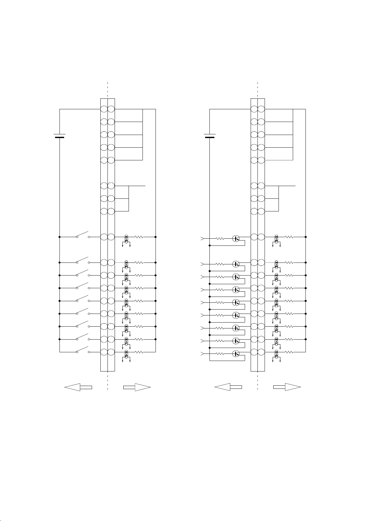
The following table shows a connection example and the light quantity at input.
The light quantity can be changed by entering SET signal(<1ms pulse signal) with a
interval more than 2ms after confirming the light quantity adjustment signal 1-8.
LED light supply may become unstable or be damaged if it is out of the range.
Use the external power supply with the capacity of the output electric current more
than 100 mA.
Light quantity control (REMOTE)
Please observe the polarity of the supply power supply output at the time of the connection.
LED light supply and the power supply may be damaged by the wrong polarity.
The external power supply the range is DC +5V - DC +24V.
2 3 2 3
2 1 2 1
2 0 2 0
1 9 1 9
1 8 1 8
1 6 1 6
1 5 1 5
1 4 1 4
2 2 2 2
1 2 1 2
1 1 1 1
1 0 1 0
9 9
8 8
7 7
6 6
5 5
+
−
DC5 〜24 V
DC power supply
COM(GND)
1
2
3
4
5
6
7
8
s w i tc h
s w i tc h
IN PU T c on n ec t or IN PUT c onnector
Dsub connector male(Pin) Dsub connector female(Socket)
resistance
resistance
photocoupler
photocoupler
inside
LED light source
(Ex.1) Use of Switch
outside
The light quantity adjustment signal SET signal
5 5
6 6
7 7
8 8
9 9
1 0 1 0
1 1 1 1
1 2 1 2
2 2 2 2
1 4 1 4
1 5 1 5
1 6 1 6
1 8 1 8
1 9 1 9
2 02 0
2 12 1
2 3 2 3
−
+
DC power supply
DC5 〜24 V
COM(GND)
1
2
3
4
5
6
7
8
transistor
IN PUT conn e ct o r INP UT co n nector
Dsub connector male(Pin) Dsub connector female(Socket)
transistor
resistance
resistance
resistance
resistance
photocoupler
photocoupler
LED light source
inside
(EX.2) Use of transistor
outside
The light quantity adjustment signal SET signal
E-7

No.5 pin No.6 pin No.7 pin No.8 pin No.9 pin No.10 pin No.11 pin No.12 pin
(Low) (High)
00000000
10000000
01000000
11000000
00100000
10100000
01100000
11100000
00010000
10010000
01010000
11010000
00110000
10110000
01110000
11110000
::::::::
11111111
0 : Short circuit 1 : Open
3)
4)
LED abnormal output
In the case of abnormality such as the opening circuit of a LED, it will internally make a short circuit
between the first pin of the INPUT connector (REMOTE IN) and the 14th pins.
The LED (orange) of the front indicator also turns on.
If the LED abnormality output appears, stop to use it and ask the manufacturer for repair.
Temperature error output
*The Light intensity table at input
Light quantity Max
↓
Light quantity UP
Course
Pin No. Light quantity
Light quantity Min(0)
When the temperature in the device rose abnormally, it will internally make a short circuit between the
4th pin and 15th pin of Input connector (REMOTE IN).
LED lamp will be light off and the indicator TEMP(red) in the front will be also light on.
If the temperature abnormality output appears, Stop the operation and contact the manufacturer.
INPUTconnector
1 6 1 6
1 5 1 5
1 4 1 4
1 1
inside
LED light source
outside
P C C
P C E
LED abnormal signal
*Abnormal:SHORT
*Normal :OPEN
1 6 1 6
1 5 1 5
1 4 1 4
4 4
inside
LED light source
outside
P C E
P C C
Temperature error signal
*Abnormal:SHORT
*Normal :OPEN
E-8

1) Communication specification
2)
1 -
2 RXD
3 TXD
4 -
5 GND
6 -
7 -
8 -
9 -
Pin No.
RS232C
9600bps
Data length
Parity bit
Stop bit
Communications protocol
4.2 RS232C、LAN(Serial communication)
8bit
Baudrate
none
1bit
* All the data for transmission and reception except STX and ETX should be
half-width capital letter. (ASCII code)
Connector specification
・RS232C Connector
* Use a straight cable to connect to a PC.
Signal
content Wiring inside
light source
No connect
To light source reception
To light source transmitter
Short circuit of 4pin - 6pin
Grand
Short circuit of 7pin - 8pin
No connect
15
9 6
PIN ASSIGNMENT for the interface(RS232C)
Interface: Dsub female(socket),25pins
* An external control I/O interface is not provided.
E-9

・LAN port (X-PORT produced by Lantronix)
Left LED
Default value
Port
IP address
Subnet mask At the factory
At the factory
Default gateway At the factory
Set value NoteItem TCP
192.168. 0.101
255.255.255. 0
Please see "command manual" for the commands in detail.
Please see "Ethernet introduction procedure for initial setting"
Right LED
0. 0. 0. 0
Communications protocol TCP/UDP
At the factory
The initial setting of the PC side is necessary to operate with the PC.
* Use a crossing cable to connect to a PC and use a straight cable to connect to the hub.
No light :No connection
Green light :100BASE-T connection state
Orange light:10BASE-T connection state
No light :No communication
Green light :Full duplex communication state
Orange light:Half duplex communication state
10001 At the factory
CONTACT 8 CONTACT 1
E-10
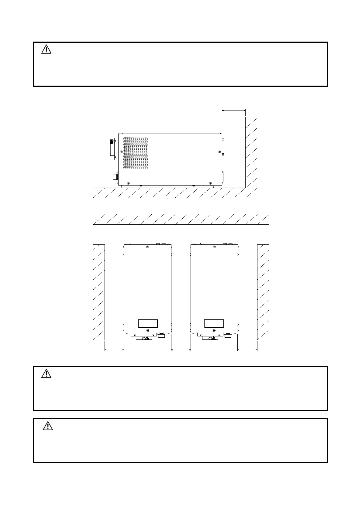
* Make sure an open upper space.
CAUTION
Do not use the product in an enclosed area, where may result in malfunction.
Do not Install to a product upside down.
Make room for ventilation so that the product's vent hole is not blocked off.
CAUTION
The AC power supply plug or AC inlet should be set for quick disconnection for emergency case.
It is customers responsibility to take care of the emergency case if the product assembled in the
customers system.
CAUTION
5. Installation
Do not use in the place exposed to dust, oil, or iron powder, where a liquid or powder is
splashed. It causes the trouble.
Do not install the LED light source near a strong electromagnetic field.
60mm and up
50mm and up 50mm and up 50mm and up
IR emitted from this product.
Do not stare at operating lamp.
Possibly hazardous optical radiation emitted
from this product.Do not stare at operating
lamp.May be harmful to the eyes.
IEC62471
WARNING
CAUTION
RISK GROUP 2
IR emitted from this product.
Do not stare at operating lamp.
Possibly hazardous optical radiation emitted
from this product.Do not stare at operating
lamp.May be harmful to the eyes.
IEC62471
WARNING
CAUTION
RISK GROUP 2
E-11

LED Color
Illuminance
Cooling System
Dimmension
Weight
*1. Illuminance : L=500mm, reference value measured at 50mm distance from the 11Φ optical fiber end.(reference value)
Input rated frequency
Power Consumption
*2. Color temperature. (reference value)
7. Specifications
Environmental
Conditions
Color Temperature(typ.)
LED Lifetime
Light
quantity control
Function
6. Outer dimensions drawing
AC100V-AC240V ±10%
50/60Hz
LA-HDF5010RL: 95W / LA-HDF7010RL: 155W
Input rated Voltage
(Subject to change without prior notice due to product improvement)
1) LED lamp ON / OFF function : External input and Front switch
2) LED abnormal output : External output and Front indicator
3) Temperature error output : External output and Front indicator
Fan
Ambient Temperature : 0℃˜ +40℃
Ambient Humidity : 20%˜ 80%RH (No dew condensation)
Indoor Use, Altitude up to 2,000m
LA-HDF5010RL: 120mm(W)×163mm(H)×265mm(D) (except protrusions)
LA-HDF7010RL: 120mm(W)×163mm(H)×315mm(D) (except protrusions)
MANUAL : Consecutive dimming by adjusting the light quantity control knob.
REMOTE : 8 bit digital light quantity control
RS232C : 256 gradation command input
LAN : 256 gradation command input
White
LA-HDF5010RL: 1,400,000Lx *1
LA-HDF7010RL: 1,800,000Lx *1
6,500K (typ.) *2
30,000H *3
LA-HDF5010RL: 4.0kg / LA-HDF7010RL: 4.6kg
*3. LED Lifetime : The lifetime may differ as you use the product under specific environment and temperature.
0
2
4 6
8
LED ON REMOTE
LED OFF MANUAL
FINE
POWER
LED
TEMP.
ALARM
LIGHT CONTROL
10
SE R IA L
L A NRS232C
STANDARD
L A N
AC100‑240V
REMOTE IN
P O W E R
RS232C
21
ON
IR emittedfrom this product.
Donotstare at operating lamp.
Possiblyhazardousopticalradiation emitted
fromthisproduct.Donotstare atoperating
lamp.May be harmful totheeyes.
IEC62 471
WARNING
CAUTION
RISK GROUP 3
120mm
155mm
109mm
LA‑HDF5010RL:265mm
LA‑HDF7010RL:315mm
※ Bottom surface:LA‑HDF7010RL
E-12

CAUTION
This product contains no replaceable parts. Please send the product to manufacturer in case you
need replacement for such as LED lamp etc.
CAUTION
Malfunctions
The LED cannot be
illuminated even if the power
is turned on.
8. Trouble shooting
Check again before asking for repair.
In case of malfunction, disconnect the power supply immediately.
The repair service should be performed by manufacturer.
The product must be shipped to manufacturer for repair.
The temperature might be
beyond the limit of the
operational temperature range
due to in the closed place etc.
Use it within the operational temperature
range. The device can be reset after
cooling the device by turning off the
power supply.
The light quantity cannot be
controlled by turning the light
quantity control knob.
Phenomenon:
The temperature abnormality
output appeared.
Check
A power supply cord may be
unplugged.
Is the control function selector
switch set to a setting other
than MANUAL?
A light quantity control knob
may be set on zero level.
Handing
Plug in.
Turn the control knob (LIGHT
CONTROL) to adjsut the light volume.
Set the control function change switch to
MANUAL.
E-13

☆
2020.05.08 IM-135-Rev.2
HONG KONG
TEL : (852)-2418-1122 FAX : (852)-2418-1235
HAYASHI TRADING (SHENZHEN) CO.,LTD.
Room 27B07, 27F, Jueshi Building, 4018 Jiabin Road,
Luo Hu District, Shenzhen 518001, CHINA
HAYASHI-REPIC CO.,LTD.
1-28, Kitaohtsuka, Toshima-Ku, Tokyo 170-0004 JAPAN
TEL : (86)-755-3685-6361 FAX : (86)-755-3685-6364
・ Details of trouble : Detailed information such as a period of use, the operating
condition at the time of trouble.
・ Date of purchase : Date of purchasing this product.
・ Your name, your company name, address, phone number and fax number.
Division-1
9. After-sale services
When you ask for a repair, let us know the following:
・ Model Name : LA-HDF5010RL or LA-HDF7010RL
・ Serial Number : Inscribed on the serial number label pasted to this product.
TEL : +81-3-3918-5623 FAX : +81-3-3918-5683
KORIN ELECTRONIC CO.,LTD.
Room 1005, Fook Yip Bldg., 53-57 Kwai Fung Crescent, Kwai Chung,
E-14
This manual suits for next models
1
Popular Lighting Equipment manuals by other brands

SPARKELEC
SPARKELEC SP-3001FE/DA-D40-WH Installation and operating instructions

Leviton
Leviton IED96-130 Guide

CCS
CCS PD2 Series Instruction guide

EuroLite
EuroLite LED PIX-6 HCL user manual

LED World
LED World HH-S2835 120-24V-C Series quick start guide

Hafele
Hafele LOOX 833.74.708 Mounting/Programming Instructions


