Hayes Endeavor 81770 User manual

Electronic Brake Controller
Hayes Brake Controller Company P/N 81770
INSTALLATION MANUAL
For trailers with 2-8 electric brakes and vehicles with 12 volt negative ground systems only.
READ AND SAVE THESE INSTRUCTIONS
•Before beginning installation, read and become familiar with these instructions.
•Leave in tow vehicle for future reference.
•IMPROPER INSTALLATION AND OPERATION COULD CAUSE PERSONAL INJURY
AND/OR EQUIPMENT AND PROPERTY DAMAGE.
•Questions on installation, adjustment, trouble shooting, or operation of brake controllers
•Call 800-892-2676 Monday through Friday between 8:00 a.m. and 5 p.m. Eastern Time.
SAFETY INFORMATION
!
!
WARNING: Indicates a potentially hazardous situation that,
if not avoided, could result in death or serious, personal injury.
CAUTION: Indicates a potentially hazardous situation that,
if not avoided, could result in damage to product or property.
TIP: Contains helpful information to facilitate installation.
Installation
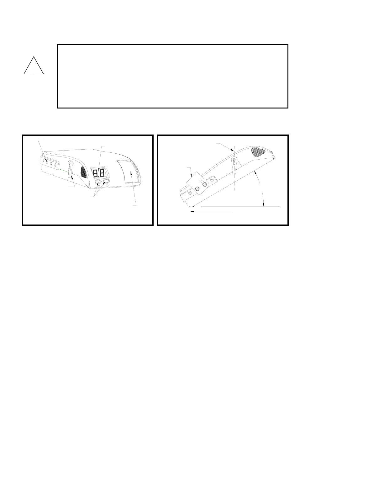
-35° to 90°
MOUNTING
BRACKET
PENDULUM ARM
STRAIGHT DOWN
FRONT OF VEHICLE
Figure 2 –
Acceptable Mounting Angles
SETUP / ADJUSTMENT
BUTTONS MANUAL OVERRIDE
SLIDE LEVER
DIGITAL
DISPLAY
ANCHOR HOLES
FOR MOUNTING
PENDULUM
LEVEL
ADJUSTMENT ARM
Fi
g
ure 1 – Front view of Endeavor
CAUTION:
•In the automatic mode and minimum power setting at 10, noticeable braking
is applied only when the sensor detects deceleration.
•With the vehicle at rest and the brake pedal depressed, there should be only
a slight output to the trailer brakes (when minimum power is set to 10).
•Higher at rest outputs and reverse braking can be obtained by increasing the
minimum power setting.
!

- 3 -
Mounting Angle
Mounting angles between –35 and + 90 degrees can be accommodated by the controller. THE UNIT
MUST, HOWEVER, BE INSTALLED SO THAT IT IS PARALLEL WITH THE TRAVEL OF THE TOW
VEHICLE AND TRAILER.
Controller Mounting & Installation
Controller and Bracket Mounting
•The bracket provided is to be used for mounting the controller to the tow vehicle.
•Use the reversible slotted bracket.
•DO NOT MOUNT CONTROLLER UPSIDE DOWN OR SIDEWAYS.
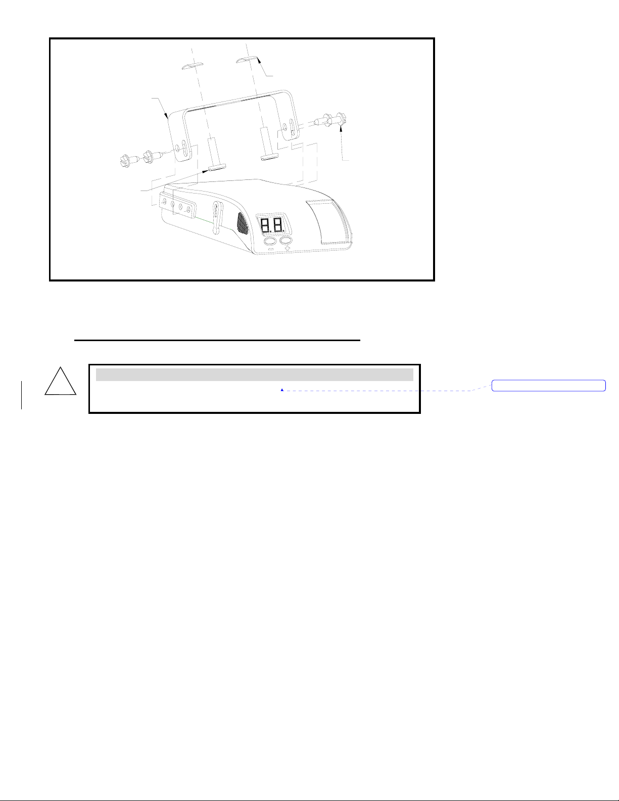
Mounting
Bracket
Pan Head
Machine Screw
Tinnerman
Nut
Self Tapping
Screws
Figure 3 – Attachment of Mounting Bracket
WARNING:
•If the controller is mounted incorrectly, the pendulum cannot operate
correctly and may cause loss of braking.
!Formatted: Font: (Default) Arial
Installation Steps
1. Install the mounting bracket to a solid surface under the tow vehicle dash using the two
machine screws and fasteners provided. Tighten until snug. See Figure 3 – Attachment
of Mounting Bracket.
2. Insert four of the self tapping screws provided through the mounting bracket holes and into
the desired controller anchor holes. Tighten until snug.
3. Mount in a location which allows the driver to easily apply the manual override slide
lever and see the digital display.
WARNING:
•All four controller wires must be connected properly for the controller to
operate correctly.
•Failure to properly connect all four wires can cause loss of trailer braking.
•Improper wiring will destroy the controller and void the manufacturer’s
warranty.
WARNING:
•Use of longer screws than those provided can damage the unit and cause
loss of braking.
CAUTION:
•Care must be taken to ensure that the mounting surface is rigid enough to
prevent excessive vibration.
•Excessive vibration may result in poor performance.
!
!
!
Formatted: Font: (Default) Arial
Formatted: Font: (Default) Arial

Read ALL wiring instructions prior to making electrical connections to the tow
vehicle.
WARNING:
Follow wiring instructions.
•Improper wiring will destroy the controller and void the manufacturer’s warranty.
!
WARNING:
To reduce the risk of injury or damage to property:
•Always connect the white wire first and the black wire second.
•All four controller wires must be connected properly for the controller to operate
correctly.
•Failure to connect the wires correctly can cause loss of trailer braking.
!
WARNING:
•The white wire must be connected to a known good ground (preferably the negative
battery post).
•Improper or no ground will result in poor controller performance or lack of
performance altogether.
•Improper ground connection can destroy the controller and void the manufacturer’s
warranty.
!
WARNING:
•Improper connections may result in no trailer brakes or destroy the controller and
void the manufacturer’s warranty.
•Refer to the vehicle manufacturer or to Hayes Lemmerz (800-892-2676) for the
latest controller red stoplight wire to stop lamp switch connections.
!
CAUTION:
•DO NOT connect the black wire to any vehicle power supply line or fuse panel that
could cause circuit overload or damage to tow vehicle wiring and vehicle
electronics.
•Route the black wire through a grommet hole in the fire wall to prevent wire
grounding and away from the radio antenna to reduce any possible AM radio
interference.
!

Controller Wiring Instructions
The following chart describes the function of each of the controller’s wires:
IMPORTANT: Make all controller wiring connections to the wiring harness before connecting the
harness to the vehicle.
Order Color Function Wire
Size
(AWG)
Connect To
1st White Ground 16 grounded metal part of the firewall or directly to the
negative (-) terminal of the battery. Connect this
wire first.
2nd
Black + connection
to the
vehicle’s
power system
12 positive (+) terminal of the battery. MUST have a
self-resetting Circuit Breaker in-line between the
controller and the battery. See chart for proper size.
Route the black wire through a grommet hole in the
fire wall to prevent wire grounding and away from the
radio antenna to reduce any possible AM radio
interference. Connect this wire second.
3rd Red Stoplight 14 non-powered stop lamp wire (of the stop lamp switch)
or trailer tow wiring harness. It is recommended that
a 20-amp inline fuse be installed between the
controller’s red wire and the stop lamp switch. The
fuse is required in 1999 & later Fords.
4th Blue Output to
trailer brakes 12 the trailer brake wire or tow vehicle / trailer connector.
SELF-RESETTING CIRCUIT BREAKER
SIZE CHART
Number of Trailer Brakes
Number of Brake Light
Bulbs (tow vehicle Plus
trailer) 2 Brakes 4 Brakes 6 Brakes 8 Brakes
4 Bulbs (minimum) 20 AMP 30 AMP 30 AMP 40 AMP
5 Bulbs 20 AMP 30 AMP 30 AMP 40 AMP
6 Bulbs 20 AMP 30 AMP 40 AMP 40 AMP
7 Bulbs 30 AMP 30 AMP 40 AMP 40 AMP
8 Bulbs 30 AMP 30 AMP 40 AMP 50 AMP
9 Bulbs 30 AMP 40 AMP 40 AMP 50 AMP
Note: Each trailer brake magnet is assumed to draw 3 amps of current and
each brake lamp bulb is assumed to draw 2 amps.
TIP:
•Special Dual-Mated “Quik ConnectTM” Wiring Harnesses are available for all Hayes
Brake Controllers fitted with a connector on the wire leads, making connection a
snap. Harnesses are available through all dealer resources. Ask specifically for the
Ha
y
es Brake Controller Com
p
an
y
(
HBC
)
brand harnesses to match
y
our controller.

Special Conditions
For tow vehicles equipped with factory trailer towing package;
•Refer to your vehicle’s owner’s manual or other information provided by the manufacturer in
determining the correct connection points for the controller.
•See Appendix section for partial list of manufacturer wiring harness to controller conversions.
For vehicles without a trailer-towing package: refer to the wiring diagram in Figure 4.
Figure 4 – Wiring Diagram
WARNING:
All 1999 and later Ford vehicles without the trailer wiring package:
•The red controller wire must be connected to the light green wire of the brake
stop lamp through a 20-amp inline fuse.
•Failure to install a 20-amp inline fuse can destroy the controller and void the
manufacturing warranty.
!
WARNING:
1989-1991 Ford Bronco, Econoline, F-Superduty, and F150-350 Series:
•The red stoplight wire MUST splice into the turn signal connector harness and
NOT to the stoplight switch.
•Connecting to the terminal of the stoplight switch will break the switch and result
in no stoplights and no trailer braking.
!

Appendix
OEM TOW VEHICLE WIRING CONVERSION
CHRYSLER (THROUGH 2002) CONTROLLER FUNCTION CHRYSLER (NEW)
RED W/BLACK TRACE BLACK +12 VOLT SUPPLY WHITE WITH RED TRACE
WHITE W/TAN TRACE RED STOPLIGHT BLUE WITH WHITE TRACE
BLUE BLUE TRAILER BRAKES BLUE
BLACK WHITE GROUND GREEN WITH BLACK TRACE
FORD (THROUGH 2002) CONTROLLER FUNCTION FORD (NEW)
RED BLACK +12 VOLT SUPPLY PINK
LIGHT GREEN RED STOPLIGHT RED
BLUE BLUE TRAILER BRAKES BLUE
WHITE WHITE GROUND WHITE
BROWN NOT USED ILLUMINATION BROWN
FORD EXPEDITION CONTROLLER FUNCTION
RED BLACK +12 VOLT SUPPLY
RED/GREEN TRACE RED STOPLIGHT
BLUE BLUE TRAILER BRAKES
BLACK WHITE GROUND
GENERAL MOTORS CONTROLLER FUNCTION
RED BLACK +12 VOLT SUPPLY
LIGHT BLUE RED STOPLIGHT
DARK BLUE BLUE TRAILER BRAKES
BLACK WHITE GROUND
BROWN NOT USED ILLUMINATION
2004 INFINITY CONTROLLER FUNCTION
RED BLACK +12 VOLT SUPPLY
RED/GREEN RED STOPLIGHT
BROWN/WHITE BLUE TRAILER BRAKES
BLACK WHITE GROUND
RED/BLUE NOT USED ILLUMINATION
RANGE ROVER CONTROLLER FUNCTION
REMOVE TAIL LIGHT & BLACK +12 VOLT SUPPLY
CONNECT RED RED STOPLIGHT
CONTROLLER WIRE TO BLUE TRAILER BRAKES
BLACK/BLUE TRACE, NO WHITE GROUND
LIGHT WITH MANUAL NOT USED ILLUMINATION
2004 TITAN/ARMADA CONTROLLER FUNCTION
RED BLACK +12 VOLT SUPPLY
RED/GREEN RED STOPLIGHT
BROWN/WHITE BLUE TRAILER BRAKES
BLACK WHITE GROUND
RED/BLUE NOT USED ILLUMINATION
2004 TOYOTA TUNDRA CONTROLLER FUNCTON
BLACK-RED BLACK +12 VOLT SUPPLY
GREEN-WHITE RED STOPLIGHT
RED BLUE TRAILER BRAKES
BROWN WHITE GROUND
Form7-2170 19083-3@B
Table of contents
Other Hayes Controllers manuals


Popular Controllers manuals by other brands

Kelly
Kelly KLS14801-8080N user manual

Siemens
Siemens LMV51 Series Basic documentation

HP
HP Compaq Presario,Presario 4400 Assembly Replacement Instructions

Smartgen
Smartgen HAT220A operating manual

Power Electronics
Power Electronics VS65 Series Hardware and installation manual

Bosch
Bosch BAT 250 Original instructions

Beckhoff
Beckhoff C6930 Installation and operating instructions

CKD
CKD AX1R Series instruction manual

Resol
Resol DeltaSol MX Manual for the specialised craftsman

Johnson Controls
Johnson Controls M9316-A Z Series installation instructions

Intiel
Intiel Dynamic Boiler Controller user manual

FUJIDENZO
FUJIDENZO FVR-2000SC Operation manual


