HAYWARD FLOW CONTROL
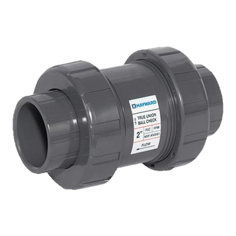
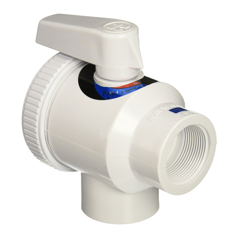
TB SERIES TRUE UNION BALL VALVE
INSTALLATION, OPERATION AND MAINTENANCE INSTRUCTIONS
PLEASE READ THE FOLLOWING INFORMATION PRIOR TO INSTALLING AND USING ANY HAYWARD PRODUCT. FAILURE
TO FOLLOW THESE INSTRUCTIONS MAY RESULT IN PRODUCT DAMAGE, PROPERTY DAMAGE, PERSONAL INJURY, OR
EVEN DEATH.
1. Hayward Flow Control (Hayward), a division of Hayward Industries, guarantees its products against defective material and workmanship only.
Hayward assumes no responsibility for property damage or personal injury resulting from improper installation, misapplication, or abuse of any
product.
2. Hayward assumes no responsibility for property damage or personal injury resulting from chemical incompatibility between its products and the
process fluids to which they are exposed. Determining whether a particular PVC, CPVC, or PP product is suitable for an application is the
responsibility of the user. Chemical compatibility charts provided in Hayward literature are based on ambient temperatures of 70°F and are for
reference only.
3. Hayward products are designed for use with non-compressible liquids.
WARNING
Hayward PVC and CPVC products should NEVER be used or tested with compressible fluids such as compressed air or
nitrogen. Use of PVC and CPVC products in compressible fluid applications may result in product damage, property damage,
personal injury, or even death.
4. The maximum recommended fluid velocity through any Hayward product is eight feet per second (8 ft/s). Higher fluid velocity can result in
damage due to the water hammer effect.
5. Piping systems must be designed and supported to prevent excess mechanical loading on Hayward products due to system misalignment, weight,
shock, vibration, and the effects of thermal expansion and contraction.
6. The effect of temperature on plastic piping systems must be considered when the systems are initially designed. The pressure rating of plastic
systems must be reduced with increasing temperature. Maximum operating pressure is dependent upon material selection as well as operating
temperature. Before installing any Hayward product, consult Hayward product literature for pressure vs. temperature curves to determine any
operating pressure or temperature limitations.
7. PVC and CPVC plastic products become brittle below 40°F. Use caution in their installation and operation below this temperature.
WARNING
Hayward PVC and CPVC products should not be used in services with operating temperature below 34°F.
8. Due to differential thermal expansion rates between metal and plastic, transmittal of pipe vibration and pipe loading forces, DIRECT
INSTALLATION OF HAYWARD FLOW CONTROL PRODUCTS INTO METAL PIPING SYSTEMS IS NOT RECOMMENDED. Wherever
installation of Hayward product into metal piping systems is necessary, it is recommended that at least 10 pipe diameters in length of plastic pipe
be installed upstream and downstream of the product to compensate for the factors mentioned above.
9. Published operating requirements are based on testing of new products using clean water at 70°F. Performance is affected by many factors
including fluid chemistry, viscosity, specific gravity, flow rate, and temperature. These should be considered when sizing Hayward products.
10. Systems should always be depressurized and drained prior to installing or maintaining any Hayward product.
WARNING
Failure to depressurize and drain system prior to installing or maintaining any Hayward product may result in product damage,
property damage, personal injury, or even death.
SOCKET CONNECTION:
Socket end connections are manufactured to ASTM D2467-94. Solvent cementing of socket end connections to pipe should be performed per ASTM
specifications D2855-87. Cut pipe square. Chamfer and deburr pipe. Surfaces must be cleaned and free of dirt, moisture, oil and other foreign
material. Remove assembly nuts and end connectors from valve body. Slide assembly nuts, with threads facing valve, onto pipe to which the end
connector is to be cemented. Apply primer to inside socket surface of end connector. Never allow primer or cement to contact valve ball or end
connector o-ring sealing surfaces, as leaking may result. Use a scrubbing motion. Repeat applications may be necessary to soften the surface of the
socket. Next, liberally apply primer to the male end of the pipe to the length of the socket depth. Again apply to the socket, without delay apply cement
to the pipe while the surface is still wet with primer. Next apply cement lightly, but uniformly to the inside of the socket. Apply a second coat of cement
to the pipe, and assemble the end connector to the pipe, rotating the end connector 1/4 turn in one direction as it is slipped to full depth on to the pipe.
The end connector should be held in position for approx. 30 seconds to allow the connection to “set”. After assembly wipe off excess cement. Full set
time is a minimum of 30 minutes at 60 to 100 F. Full cure time should be based on the chart below.
JOINT CURE SCHEDULE:
The cure schedules are suggested as guides. They are based on laboratory test data, and should not be taken to be the recommendations of all
cement manufacturers. Individual manufacturer’s recommendations for their particular cement should be followed.
Test Pressures for Pipe
Sizes ½” to 1-1/4”
Test Pressures for Pipe
Sizes 1-1/2” to 3”
Test Pressures for Pipe
Sizes 4” & 5”
Test Pressures for Pipe
Sizes 6” to 8”
Range During
Cure Period(B)
180 PSI
(1240 kPa)
to 370 PSI
(1240 to
180 PSI
(1240 kPa)
to 315 PSI
(1240 to
180 PSI
(1240 kPa)
315 PSI
(1240 to 2172
180 PSI
(1240 kPa)
to 315 PSI
(1240 to
Colder than 10 (-15) Extreme care should be exercised on all joints made where pipe, fittings or cement is below 10ºF.
A: It is important to note that at temperatures colder than 20ºF on sizes that exceed 3 in., test results indicate that many variables exist in the actual cure rate of the joint. The
data expressed in these categories represent only estimated averages. In some cases, cure will be achieved in less time, but isolated test results indicate that even longer
periods of cure may be required.
B: These cure schedules are based on laboratory test data obtained on Net Fit Joints (NET FIT=in a dry fit the pipe bottoms snugly in the fitting socket without meeting
interference).
