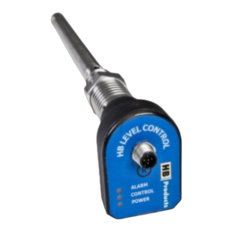
HB Products HBDF-MK2 Use and care manual

WWW.HBPRODUCTS.DK 1 / 12
Installation and calibration manual
HBDF – Mk2 Defrost Sensor
Introduction
The HBDF sensor measures the ice thickness on an evaporator and delivers an analog signal which can be used in a
PLC for controlling the defrost. The sensor is suited for cold rooms, blast freezers and cold stores where temperatures
are below 0°C. If the sensor is used for heat pumps and similar applications where the evaporator get wet special
settings are needed and the installation is more critical to secure success. Please contact HB support before the
installation.
Besides providing input for a PLC, the sensor can also provide other outputs for systems without a classic PLC. The
sensor has these three outputs.
•Simple analog: Provide a simple analog signal 4-20 mA linear to the ice thickness for a PLC.
•Smart analog: Provide an analog signal when the specified ice thickness is reached and when defrost can be
ended.
•Relay output: In this mode the defrost can be controlled by relays based on parameters in the sensor.
The sensor is equipped with a temperature sensor which detects when the ice is melted and the defrost cycle is
complete. This is a smart solution to avoid unnecessary defrost.
The sensor has a M12 interface like other HB-product sensors and is configured by the HB tool. The product consists of
a box, a ground cable, the measuring wire, and a temperature sensor.
The sensor is based on the capacitive measurement principle and reacts on ice and water between the wire and the fins
in the evaporator. This means the wire must be mounted between fins where ice builds up and the fins must be
grounded.

HBDF mk2 instruction manual 15 EN June - 2021 WWW.HBPRODUCTS.DK 2 / 12
Table of Contents
Intoduction .............................................................................................................1
Table of Contents ...................................................................................................1
Safety Instructions..................................................................................................2
Installation..............................................................................................................3
Wiring the sensor....................................................................................................5
Sensor configuration...............................................................................................6
Operating modes.....................................................................................................6
Sensor setup............................................................................................................7
Calibration of sensor.............................................................................................11
Technical data.......................................................................................................12
Sensor Repair .......................................................................................................12
Spare Parts............................................................................................................12
Safety Instructions
CAUTION! Always read the operational guidelines before commencing work! Read all warnings Installation of HBDF
requires technical knowledge of both refrigeration and electronics. Only qualified personnel should work with the
product. The technician must be aware of the consequences of an improperly installed sensor and must be committed to
adhering to the applicable local legislation.
If changes are made to type-approved equipment, this type of approval becomes void. The product's input and output, as
well as its accessories, may only be connected as shown in this guide. HB Products assumes no responsibility for
damages resulting from not adhering to the above.
Explanation of the symbol for safety instructions. In this guide, the symbol below is used to point out important safety
instructions for the user. It will always be found in places in the chapters where the information is relevant. The safety
instructions and the warnings must always be read and adhered to.
CAUTION! Refers to a possible limitation of functionality or risk in usage.
NOTE! Contains important additional information about the product and provides further tips.
The person responsible for operation must commit to adhering to all the legislative requirements,
preventing accidents, and doing everything to avoid damage to people and materials.
Intended use, terms of use. The HBDF defrosting sensor is designed for measuring ice formation on evaporators. If the
HBDF is to be used in a different way and if the operation of the product in this function is determined to be
problematic, prior approval must be obtained from HB Products.
Defrosting with hot gas must be performed in a safe way to ensure that there is no risk for liquid hammering and
leakage of refrigerant.
Preventing collateral damage: Make sure that qualified personnel assess any faults and take necessary precautions
before attempting to make replacements or repairs, to avoid collateral damage. Disposal instructions: HBDF is
constructed so that the modules can easily be removed and sorted for disposal.

HBDF mk2 instruction manual 15 EN June - 2021 WWW.HBPRODUCTS.DK 3 / 12
Installation
How to install the electronic box and temperature sensor
Installation of controller box and temperature sensor if used.
1) The sensor box is installed on the frame of the evaporator.
2) Ground wire should be connected to the frame. We recommend using stainless screw with a star
washer/disc and cover/applying silicone grease/compound around the connection to avoid
corrosion. It is important that the evaporator fins are connected electrically to ground –it will not
work without.
3) Normally installed with a standard unshielded cable. If the EMC is higher than described in
EN 61326, a shielded cable must be used.
4) If possible, look at the evaporator in operation and notice where the ice is formed and where the ice
remains during defrost.
5) The temperature sensor must be mounted between the fins at the bottom of the evaporator section
where the ice remains longest when defrosting. The tip of the temperature element is where the
sensor is located –make sure it is far away from the defrost heating source hot gas/electrical
element.
Where to install the wire
The built up of ice is very different depending on the type of system and the application. The wire must be between the
fins where ice will built-up. It can be on the inlet side, on the outlet side or in the middle of the evaporator.
If you have the overview of where ice is building up, you do not need to wire the complete evaporator if the area wired
is where you get ice. If you don not have any idea of where the ice will built-up this is the general rules:
•For direct expansion systems and brine systems: Ice will be formed close to the liquid inlet/expansion valve
and typically the area close to the liquid outlet will be free from ice due to superheat. The superheated area is
often on the air inlet side, and here the wire should not be installed as no ice built up here.
•For pump circulated system: Most ice will be formed close to the liquid outlet but in general the ice
distribution will better that for DX systems.
The wire can be installed on the air inlet side on the outlet side, or it can pass through the evaporator. Again, it depends
on the design and you should follow the liquid pipes depending on the type of system as described above.
How to install the wire
The wire can be fixed to the evaporator using three methods:
1. Going forth and back the pipes.
2. Using the special clips attached to the pipes.
3. Going through the evaporator
You can choose the method best suited for the evaporator if it is installed
where ice is formed. The most stabile installation method is to go forth and
back the pipes.
1
2
3

HBDF mk2 instruction manual 15 EN June - 2021 WWW.HBPRODUCTS.DK 4 / 12
If ice formation is unknown place the wire all over the inlet side for a flooded evaporator like shown on the drawing.
For a DX evaporator the wire must pass through the evaporator.
The distance between the vertical sections of the wire (windings) can be varied from 100 to
1000mm depending on evaporator size and wire length. When estimating length to be ordered,
consider both the vertical sections of the wire and the connecting, horizontal arches.
Note: when calibrating the HBDF, only consider the active, vertical sections of the wire. The
wire length is measured in mm.
The free end of the wire must end outside the evaporator, and it must be isolated from the
evaporator. Use the terminal connector delivered together with the wire.
HBDF-snap on Clip can be used for securing the wire but passing behind the pipes provide a better and more secure
fastening. The clip requires minimum 5 mm fin spacing.
Installation examples
The wire does not need to cover the entire surface as long as it is installed in an area where ice is formed.
Overfeed evaporator –the wire is mounted on the air inlet side
Sensor PT1000 location (Example)
The active part is the
vertical sections of
the wire placed
between fins.
Not active
PT1000
Piping in mm
Clips
8-10 mm
HBDF-snapONClips8
10-12 mm
HBDF-snapONClips10
12-14 mm
HBDF-snapONClips12
14-16 mm
HBDF-snapONClips14
16-18 mm
HBDF-snapONClips16
19-22 mm
HBDF-snapONClips19
22-25 mm
HBDF-snapONClips22
The temperature sensor should
be placed were ice melt slowly.
Keep away from the hot tubes
or electrical elements used for
defrosting.

HBDF mk2 instruction manual 15 EN June - 2021 WWW.HBPRODUCTS.DK 5 / 12
Direct expansion evaporator
On DX evaporators, the first evaporator tubes are often placed in the air-inlet to ensure superheating, which means that
there is not enough cooling power to form ice build-up. If possible, observe where ice is formed and place both wires
and temperature sensor there.
Sensor wire is passed in/out through the evaporator from the inlet side to the outlet side as shown.
The second picture show ice on the air outlet side of a DX evaporator where there is limited ice formation on the inlet
side.
Air inlet side with limited ice due to superheat.
Air outlet side on the same evaporator covered
blocked with ice
Here is the correct wiring
shown on a direct expansion
evaporator. The wire is going
through the evaporator.

HBDF mk2 instruction manual 15 EN June - 2021 WWW.HBPRODUCTS.DK 6 / 12
Wiring the sensor
The HBDF Mk2 use screw terminals and a M12 plug for communication and setup. The sensor needs power
connection to be setup and to have the correct function of the relays.
Wiring the HBDF Mk2
When the wire, ground cable and temperature sensor is mounted on the evaporator it is connected in the box. The
picture show the inside of the box and it should be straight forward.

HBDF mk2 instruction manual 15 EN June - 2021 WWW.HBPRODUCTS.DK 7 / 12
Simple defrost with electric heater.

HBDF mk2 instruction manual 15 EN June - 2021 WWW.HBPRODUCTS.DK 8 / 12
Sensor configuration
All HB-product sensors can be configured using a laptop and a “M12-USB”cable. The software can be downloaded
freely on the HB products web page. The configuration data can be stored in the sensor and will be there until erased
even without power connection—just like you store data on a memory stick. When you change a value/setting there will
be put a check mark next to it and that indicates you have changed something and need to store the data in the sensor.
The sensor has three different operation modes.
The sensor mode is selected in the basic settings.
Simple analog
In this mode the sensor provides an analog signal 4-20 mA linear to the
ice thickness. The temperature sensor is only used to eliminate
measurements when the sensor is wet. The only additional data
processing done is an averaging of the output based on the filtering
constant.
Parameters used for controlling the output:
•Filter time constant - averaging time in sec
•Disable temp –above this temperature the output will be 4 mA because the measurement is invalid
due to water.

HBDF mk2 instruction manual 15 EN June - 2021 WWW.HBPRODUCTS.DK 9 / 12
Smart analog
In this mode the sensor provides an analog signal 4-18 mA linear to the ice thickness until the ice thickness
is reached. Then the sensor has a constant output of 18 mA until the temperature reach the specified value
indicating that the defrosting is done. At this point the output is 19 mA for a period defined by a
parameter. When the time has passed the evaporator should be dry and free from ice –ready for a new
cycle.
Parameters used for controlling the output:
•Filter time constant - averaging time in sec
•Disable temp –above this temperature the output will be 4 mA, because the measurement is
invalid due to water.
•Defrost start in % - defines the ice thickness when defrost should start.
•Defrost stop temp °C - defines the temperature in °C at which the defrosting has ended.
•Sensor delay in min - defines the time in minutes where the sensor is wet and output is 4 mA

HBDF mk2 instruction manual 15 EN June - 2021 WWW.HBPRODUCTS.DK 10 / 12
Relay
In this mode the sensor provides both an analog signal 4-20 mA linear to the ice thickness and keep the
relays inactive until the ice layer is reached. When the specified ice layer is reached relay1 is activated and
it can be used for controlling the defrost/heating and switching of the compressor. Relay1 is activated until
the temperature sensor measures the elevated temperature indicating that the defrosting is done. When
this temperature is reached Relay1 is deactivated and Relay2 is activated for a period (sensor delay time).
This Relay2 can be used for initiating the fan to blow the water out of the evaporator or to prevent the fan
from blowing the water out.
During the defrost time and sensor delay time the analog signal is fixed to the mA output determined by
the set point (defrost start in %). When the time has passed the evaporator should be dry and free from ice
–ready for a new cycle.
Parameters used for controlling the output:
•Filter time constant - averaging time in sec
•Disable temp –above this temperature the output will be 4 mA.
•Defrost start in % - defines the ice thickness when defrost should start.
•Defrost stop temp °C - defines the temperature in °C at which the defrosting has ended.
•Sensor delay in min - defines the time in minutes where the sensor is wet and output is 4 mA

HBDF mk2 instruction manual 15 EN June - 2021 WWW.HBPRODUCTS.DK 11 / 12
Calibration of the sensor
The sensor can be calibrated using three different methods:
When typing in the active wire length and the distance between the fins the basic calibration is calculated, and the
sensor is working, but the accuracy can be improved by making a zero calibration. The calibration is always done when
the evaporator is dry and without significant ice
Using the green button in the box
Press the green button until the red LED turn off
Press the green button once and the calibration is done
Using the HB-tool
Connect power supply to the box
Connect the HB-tool to the box
Open basic settings tab
Click on the zero-calibration button.
Calibration - when using the thin wire
When the sensor is installed and the evaporator is dry
and without ice, connect the sensor to the HB-tool
using a USB cable.
•Open basic settings tab
•Click on the zero-calibration button.
•Click on the small box at the bottom of the
page
•Type in the same value as the zero calibration
into the field called “SPAN calibration in pF”
•Click on “Send Zero/Span values”

HBDF mk2 instruction manual 15 EN June - 2021 WWW.HBPRODUCTS.DK 12 / 12
LED indication
1) Green LED, flash indicates power supply, And DI external start signal is ON.
2) Red LED indicates Defrost mode or sensor error (Outside measuring range).
LED signal
ON/OFF/Frequency
Functionality
Green
On or flash
Supply voltage connected
Flash (Run-In mode)
Run-in start signal / operation.
OFF
No supply voltage
Red
Flash
Defrost mode “ start”
Flash quickly
Defrost mode “stop”
OFF
Defrost fan/sensor delay (timer end)
Fault Detection
Fault
Reason
Correction of fault
No LED is on / no function
No supply to the sensor or defective
cable.
Check for fault in the power supply
or replace the supply cable.
Sensor does not provide a useable
mA signal and relays does not work
The “Enable start/stop”is set to on
and no digital signal is provided
Set the Enable start/stop is set to off
if you don’t like to use this function.
Red LED is flashing
Power supply is too small.
Install a power supply with a
capacity of at least 30 W.
Very high actual measurement
(above 5000 pF)
The wire is shorted to the evaporator
fins
Make sure the end of the wire is
outside the evaporator and use the
terminal connector.
If that doesn’t solve the problem the
wire has to be replaced.
No analog output or Relay contact
activation
There may be bad ground
connection to the frame.
Clean the metal surface and protect it
with special compound/grease.
Practical measurement of output signals: 4-20 mA signal: Function and stability of the 4-20 mA signal can be checked
by connecting a hand-held multimeter. If the supply is connected and the power LED flashes and there is no output
signal, the electronics may be defective.
Sensor Repair
In case of defects with the sensor, it will typically only be necessary to replace the electronical part.
Complaints are processed by HB Products’ dealers/distributors.
Please consider their complaint procedures before returning the sensor.
Spareparts
Position
Designation
Specification
Product number
1
Mechanical part
10 m wire
HBDF-MEK-10M
Mechanical part
20 m wire
HBDF-MEK-20M
Mechanical part
30 m wire
HBDF-MEK-30M
2
Electronic part
PCB
HBDF-MK2-EL
3
Temp. sensor
Pt1000-Cable type
HBPT-Pt1000 cable
4
Communication cable
HB USB cable
HBxC-USB
Note! All terminals are protected against improper termination for a supply voltage up to 40 V. If
the supply voltage is higher than 40 V, the electronics will be damaged.
Other manuals for HBDF-MK2
1
Table of contents
Other HB Products Measuring Instrument manuals
Popular Measuring Instrument manuals by other brands

Heathkit
Heathkit HM-2140 manual

Small HD
Small HD 503 quick start guide

Mianyang Weibo Electronic
Mianyang Weibo Electronic DJS5179 instruction manual

RDS Technology
RDS Technology Master Driers MMM 100 Software update guide

janitza
janitza RCM 202-AB User manual and technical data

Crowcon
Crowcon APM 145 operating instructions