Bin Master 3DLevelScanner-MVL User manual

www.binmaster.com
3DLevelScanner
S-M-MV
&
HE Models
Operating Instructions
>Non-contact
>Dust-penetrating
>Multiple-point
measurement
>Optional 3D
visualization

3DLevelScanner Operating Instructions © 2012 BinMaster all rights reserved 1
Contents
1ABOUT THIS DOCUMENT........................................................................................ 3
1.1 SYMBOLS IN USE ........................................................................................................ 3
1.2 FOR YOUR SAFETY ...................................................................................................... 3
1.3 STORAGE AND TRANSPORT........................................................................................... 4
23DLEVELSCANNERᵀᴹ OVERVIEW ............................................................................ 5
2.1 THEORY OF OPERATION .............................................................................................. 5
2.2 WIDE APPLICATION RANGE ......................................................................................... 5
2.3 ADVANTAGES............................................................................................................ 5
2.4 MODELS .................................................................................................................. 6
3PHYSICAL INSTALLATION ........................................................................................ 7
3.1 LOCATION AND POSITIONING GUIDELINES ....................................................................... 7
3.2 SCANNER ORIENTATION .............................................................................................. 9
3.3 SITE PREPARATIONS ................................................................................................. 10
3.4 ASSEMBLY AND MOUNTING....................................................................................... 11
3.5 WIRING ................................................................................................................. 14
4FIRST-TIME ACTIVATION ...................................................................................... 18
4.1 LOCAL USER INTERFACE ............................................................................................ 18
4.2 SWITCHING ON THE SCANNER..................................................................................... 19
4.3 FIRST-TIME ACTIVATION STEPS SUMMARY .................................................................... 20
4.4 INITIAL SETUP PROCEDURE......................................................................................... 20
5DIFFERENT CONNECTION METHODS .................................................................... 21
5.1 4-20MACONNECTION ............................................................................................. 21
5.2 HART COMMUNICATION.......................................................................................... 21
5.3 RS-485 COMMUNICATION ....................................................................................... 22
5.4 COMMUNICATION USING THE 3DLINKPRO ................................................................... 22
5.5 TCP/IP COMMUNICATION ........................................................................................ 22
APPENDIX A: ONBOARD CONFIGURATION .................................................................. 23

2 3DLevelScanner Operating Instructions © 2012 BinMaster all rights reserved
OUTPUT SETTINGS.............................................................................................................. 23
DISPLAY SETTINGS .............................................................................................................. 25
DEVICE INFO...................................................................................................................... 26
DEVICE RESET .................................................................................................................... 27
APPENDIX B: MAINTENANCE ....................................................................................... 28
APPENDIX C:RECOMMENDED TOOLS ......................................................................... 29
APPENDIX D:SPECIFICATIONS...................................................................................... 30
TECHNICAL DATA ................................................................................................................ 30
DIMENSIONS ..................................................................................................................... 33
APPENDIX E:STANDARDS & APPROVALS .................................................................... 35

3DLevelScanner Operating Instructions © 2012 BinMaster all rights reserved 3
1About this Document
This operation manual provides detailed product related information, installation, setup and
operation instructions for 3DLevelScanner models S, M and MV. The manual is designed
for trained personnel. Please read it entirely and carefully before unpacking and
installation of the products.
1.1 Symbols in use
The following symbols indicate different sections of additional information as
follows:
IMPORTANT: An indication for additional information, tips, hints or an indication
of helpful additional knowledge.
WARNING: Indication of a potentially dangerous situation, which could result in
serious injury to persons and/or damage to the 3DLevelScanner.
EX APPLICATION:An indication of special instructions relevant to installations in
hazardous locations.
1.2 For your safety
Authorized personnel
All operations described in this manual must be carried out by authorized, trained
personnel only. For safety and warranty reasons, any internal work on the scanners must
be carried out by manufacturer-authorized personnel only.
Warning about misuse
Inappropriate or incorrect use of the scanner may result in hazards and application-specific
malfunctioning such as vessels overfilling or damage to system components through
incorrect mounting or adjustments.
If the 3DLevelScanner is used in a manner not specified in this manual, the protection
provided by the 3DLevelScanner will be impaired.
About this Document ● Storage and transport
4 3DLevelScanner Operating Instructions © 2012 BinMaster all rights reserved
General safety instructions
The 3DLevelScanner is a high-tech device requiring strict observance of standard
regulations and guidelines. The user must strictly follow the safety instructions in this
operating manual. Local and national electrical codes and all common safety regulations
and accident prevention rules should be considered during installation as well.
CE conformity
The 3DLevelScanner conforms to CE's EMC and NSR standards. CE conformity is as
follows:
EMC
EN 61326-1: 2006
CISPR 11: 2003 Class A
IEC 61000-4-2: 2001 Air Discharge, 8kV
IEC 61000-4-3: 2002 80-1000MHz, 1V/m; 1.4-
2GHz, 1V.m;
2.0-2.7GHz, 1V/m
IEC 61000-4-4: 2004 Power Lines: 1kV; Signal Lines: 0.5kV
IEC 61000-4-6: 2004 0.15-
80MHz 1VRMS, 80% A.M. by
1kHz Power & Signal Lines
NSR
(73/23/EWG)
EN 61010-1: 2001
FCC conformity (EMC)
FCC Part 15, Sub-part B, Class A.
Safety information for Ex Areas
EX-AREAS: Please note the Ex-specific safety information for installation and
operation in Ex areas. These safety instructions are part of the operating
instructions manual that comes with Ex-approved scanners.
WARNING: Substitution of components may impair Intrinsic Safety.
WARNING: For preventing ignition of flammable or combustible atmospheres,
read, understand and adhere to the manufacturer’s live maintenance procedures.
1.3 Storage and transport
The scanner is protected by special packaging during transport, and is guaranteed to
handle normal loads during transport.

3DLevelScanner Operating Instructions © 2012 BinMaster all rights reserved 5
23DLevelScannerᵀᴹ Overview
2.1 Theory of Operation
The BinMaster 3DLevelScanner™is the only device available which delivers accurate
measurement of bulk solids and powders –regardless of material type, product
characteristics, storage silo type, size, bin or container, and harshness of the storage
environment. The product incorporates a unique dust-penetrating technology to achieve an
unrivalled degree of process measurement and inventory control.
The 3DLevelScanner™includes an array of three antennas that generate low frequency
acoustic signals and receive echo signals from the contents of the silo, bin, or other
container type. Using these antennas, the unit measures not only the time/distance of
each echoed signal but also its direction.
The built-in Digital Signal Processor digitally samples and analyses the echoed signals
and produces accurate measurements of the level, volume, and mass of the stored
contents, and generates a 3D representation of the position and form of the material within
the container for displaying on remote computer screens.
2.2 Wide Application Range
The 3DLevelScanner™measures virtually any kind of solid material, stored in a variety of
containers, including large open bins, bulk solid storage rooms, stockpiles and
warehouses, mapping loads that randomly form over time inside silos, and many other
challenging applications that were not possible until now.The sensor can measure ranges
of up to 70m (200ft) and generate 3D mapping of the material surface.
2.3 Advantages
Service and maintenance-friendly -Non-contact measuring principles, the
3DLevelScanner™is easy to service and maintain
Ideal for solid volume measurement applications
The only available device that measures minimum and maximum levels
Suitable for measuring all solid materials (including ones with low dielectric constants)
Operates in dusty and moisture environments
Profiles of buildup of materials to vessel walls
Self-cleaning antenna

3DLevelScannerᵀᴹ Overview ● Models
6 3DLevelScanner Operating Instructions © 2012 BinMaster all rights reserved
3-Dimensional mapping visualization tool for filling-point choosing assistance (in
vessels with multiple filling points)
The most reliable sensor available - includes 3 transmitters and 3 receivers
2.4 Models
The 3DLevelScanner™line of products consists of three models: S, Mand MV.
Model S
The S model determines the average level of the stored contents and average distance
from the scanner to the surface of the material. Based on a 30°beam angle, the S model
is ideal for small and narrow vessels of up to 4m (13 ft) in diameter.
Model M
The M model yields highly accurate readings of level and volume. It is appropriate for large
vessels of up to 15m (50ft) in diameter and at least twice as high (30m / 100ft), open bins
and stockpiles. It is based on a 70°beam angle. The M model also presents the minimum
and maximum Level/Distance measurements along with the calculated average.
Model MV
The MV model is identical to the M model, with the additional capability of generating a 3-
dimensional representation of the stored contents on a remote computer. This feature is
highly useful for mapping buildup loads that form randomly over time and other
irregularities.
All three models are available in various modes, such as ATEX approved, FM approved,
and non-ATEX (for more information, see Approvals on page 37) and also available with
neck extension (see Appendix B: Accessories: Neck on page 30).
Each of the models is available in two temperature ranges:
3DLevelScanner II is compatible in applications where the maximal temperature in the
surroundings inside the vessel is up to 85°C (185°F).
3DLevelScanner II HE is compatible in applications where the maximal temperature in the
surroundings inside the vessel is up to 120°C (248°F).
All references in this manual to the 3DLevelScanner can be referred to as
3DLevelScanner or simply the scanner, if nothing else is mentioned it applies to any of the
scanner’s models.

3DLevelScanner Operating Instructions © 2012 BinMaster all rights reserved 7
3Physical Installation
This chapter describes the necessary steps for proper installation of the 3DLevelScanner
beginning with important pre-installation considerations such as environmental conditions,
correct positioning and orientation, through the mounting and configuration process.
3.1 Location and positioning guidelines
Choosing the proper location to the 3DLevelScanner™should consider every aspect of
the vessel and contained materials, including the silo or vessel dimensions, type of
material and angle of repose, locations of filling and emptying points, maximum level of
material, internal construction and moving part and any other consideration which may
possibly affect the scanner performance. BinMaster strongly recommends installing the
3DLevelScanner according to the 3DScanner Locator PC software for properly choosing
installation location and positioning. In case of no satisfying software solution, please
contact BinMaster Customer Support for assistance with the positioning.
Moisture and water condensation
Use the recommended cable gland and tighten the cable connection.For
additional protection against moisture, lead the connection cable downward in
front of the cable entry. Rain and condensation water can thus drain off. This
applies mainly to mounting in areas where moisture is expected (e.g., by cleaning
processes), or on cooled or heated vessels.
Measuring range
The measuring range is set in the scanner and defined by silo dimensions and the full and
empty calibration levels. These levels set the 100% and 0% values relatively.
The scanner measurements are calibrated to the top of the
body. If the scanner is lowered, or mounted with neck
extension or head-body separation, it is important to adjust
all measurements to the top of the body.
NOTE: If the material level reaches the antenna,
buildup could form inside the horn over time and
cause measurement errors or damage to the
membranes.
NOTE: the 3DLevelScanner™has a 500mm (16 ”)
of dead zone (or blanking zone).

Physical Installation ● Location and positioning guidelines
8 3DLevelScanner Operating Instructions © 2012 BinMaster all rights reserved
Pressure
The process fitting must be sealed in the case of a low pressured vessel. Before usage,
verify that the sealing material is resistant to the stored medium. The maximum allowed
pressure (stated in page 35: Appendix E: Specifications) is indicated on the label of the
sensor.
Installation location
Choosing the proper installation location for the 3DLevelScanner is an important part of
the installation process. A wrong location may result in erroneous measurements or loss of
performance.
The usage of the 3DScanner Locator Software is recommended for finding the optimal
location, which is based on various parameters.
The following factors must be taken into consideration while choosing the installation
position: vessel dimensions, filling and emptying point locations, internal structure or
support and other restrictions related to vicinity to noisy devices (such as electrical motor)
and any other element which may affect the proper operation of the scanner.
IMPORTANT: When mounting the 3DLevelScanner, do not install the scanner
near
the vessel wall
. The installation must consider the vessel dimensions.
Installi
ng the scanner near the side wall will result in bad performance.
Installing the 3DLevelscanner at the center of the vessel is not recommended, since the
perfect symmetry from all sides toward the scanner may affect the echoes distinction.
The scanner cannot be mounted at a distance lower than 500mm (16") from the wall.
When choosing the installation location, consider the filling and emptying points.
Use the 3D Scanner Locator PC software for choosing a proper location.

Physical Installation ● Scanner Orientation
3DLevelScanner Operating Instructions © 2012 BinMaster all rights reserved 9
3.2 Scanner Orientation
Mounting direction
Mounting of the 3DLevelScanner at a specific direction is
important. The ridge on the horn body, and the notch on the
top of the thread (representing antenna no.1) should be
directed toward the center of the vessel.
Mounting direction. 00indication toward vessel center
Standpipe mounting
When mounting the scanner using a standpipe part it
should be assembled and positioned at a height that
leaves at least 10mm (0.4") out of the standpipe, for the
antenna end protrudes, as shown in the figure to the
right.
IMPORTANT: Any obstruction as
well as rails, frames or support beams
should never interfere with the
acuostic beam transmitted and
received, as shown in the figure to the
right.
This comment applies to all
3DLevelScanner models including the
S model.
Wrong Correct
The 00label location

Physical Installation ● Site Preparations
10 3DLevelScanner Operating Instructions © 2012 BinMaster all rights reserved
Inflowing material
Do not mount the scanners in or above the filling stream, not too
far from the stream, and not in the direction of the filling stream in
case it is diagonal, to avoid damage to the scanner from the
flowing material. The scanner should be located with a clear line
of sight to the top of the material at high levels, not to be affected
by the filling stream or the noise it creates.
Fitting
The fitting area should be prepared to maintain the
horns/antennas vertically positioned to the ground,
as shown in the figure.
Wrong Correct
3.3 Site Preparations
IMPORTANT: The site preparations described in this section must be complete
and
verified prior to installation. For optimal installa
tion, ensure that the
3DLevelScanner can be positioned and fitted according to the guidelines
described in the beginning of this chapter.
For a list of items recommended to prepare before installing the 3DLevelScanner,
refer to
page 34: Appendix D: Recommended Tools.
Before installing, make sure the following preparations have been completed.
Power
Connecting the 3DLevelScanner chassis to the facility grounding is important for
protection.
A 24VDC (1.5 Watt) power supply must be prepared and ready to use near the
scanner mounting location.
The 3DLevelScanner is a 4-Wire device. The voltage supply and data output (4-
20mA) are carried along two separated two-wire connection cables.

Physical Installation ● Assembly and Mounting
3DLevelScanner Operating Instructions © 2012 BinMaster all rights reserved 11
Communications
Route communication cables in proper conduits and use a proper cable type.
The cable used for RS-485 should be of twisted-pair type, shielded, with 120 Ohm
impedance and approved for RS-485 communications.
The cable used for 4-20mA should be rated for analog signals, twisted-pair, low
resistance and shielded.
3.4 Assembly and Mounting
Package Contents
The supplied package includes:
3DLevelScanner sensor
Documentation
CD with the 3DLevel Manager software and marketing materials
Cable glands accessory kit
Ex-specific safety instructions (with Ex versions)
Certificates if applicable
Included components
The 3DLevelScanner includes the following components:
3DLevelScanner Body 3DLevelScanner Head
3DLevelScanner Body: Includes three antennas, transducers and temperature sensor.
The flange is mounted on the body and tightened to it.
3DLevelScanner Head: Includes the electronic board and all wiring connections. The
Head is mounted on the body.
Physical Installation ● Assembly and Mounting
12 3DLevelScanner Operating Instructions © 2012 BinMaster all rights reserved
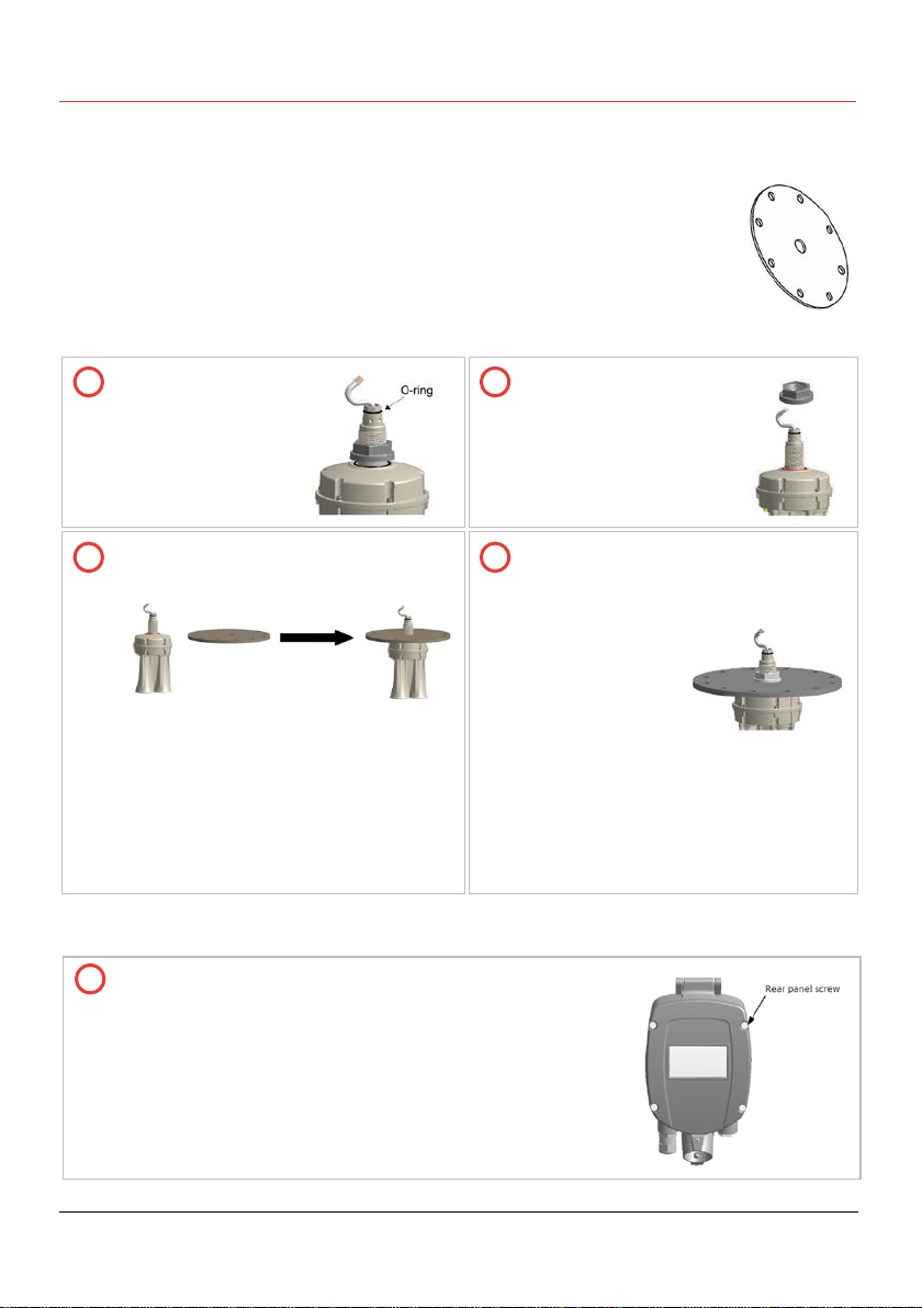
Flange preparation
Prior to the installation of the 3DLevelScanner, an installation flange should
be prepared. The flange must have a 52mm (2.05") hole for the scanner
body thread insertion.
BinMaster provides two types of standard flanges. Please refer to page 28:
Appendix B: Accessories for flange specifications.
Installing the Flange
Verify the O-Ring
on the neck tube
remains in place as
shown:
Use 18 " adjustable
pliers or 24 " wrench
to untighten and
remove the nut from
the neck tube.
Place flange over the neck tube,
insert until placed as shown: Replace the nut and tighten it over
the neck tube to the flange, using
an 18 " adjustable wrench.
Make sure the
scanner is well
tightened to the
flange to
prevent
vibration and for proper sealing.
When mounting the scanner body
and flange to the silo standpipe
make sure the scanner is facing the
center of the silo as described in
Scanner Orientation on page 9.
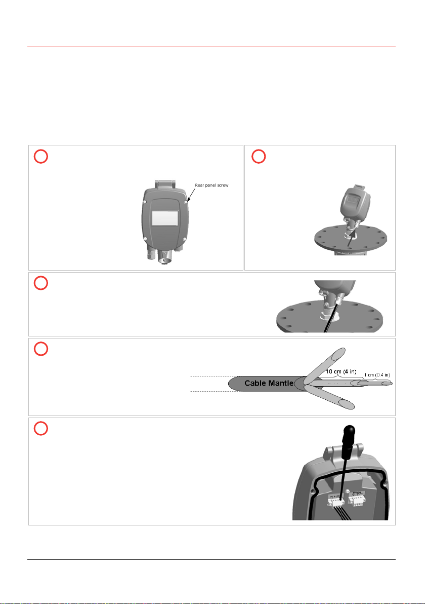
Installing the Scanner Head
Unpack the scanner head.
Untighten the four screws of the housing rear panel
using a 4mm hex key, and remove the rear panel. The
screws are of captive type and will not fall off.
1
2
3
4
1
Physical Installation ● Assembly and Mounting
3DLevelScanner Operating Instructions © 2012 BinMaster all rights reserved 13
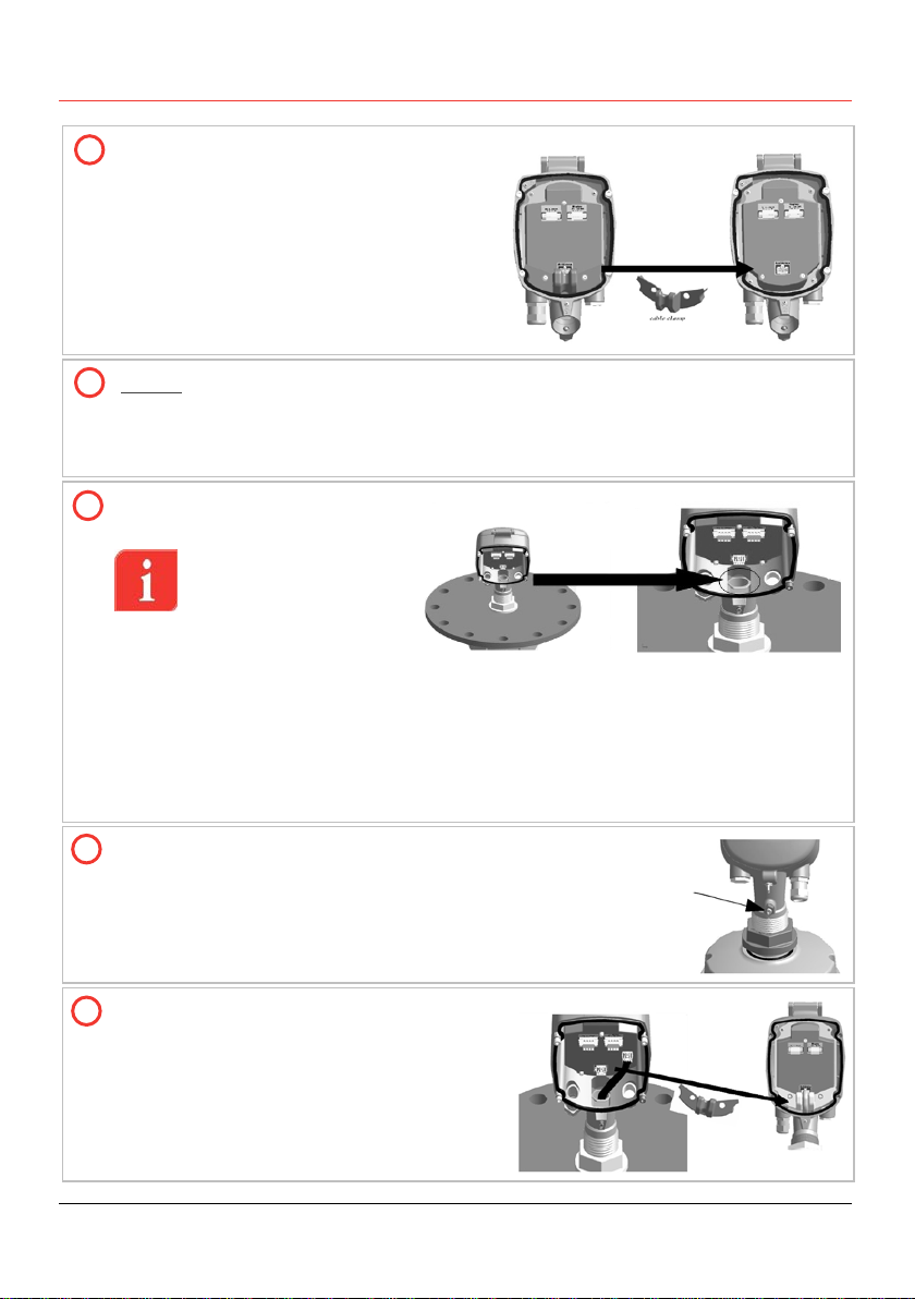
Remove the cable clamp located at the
bottom inside the scanner as shown.
Gently insert the antenna cable through the scanner head. Make sure not to
damage the (white) cable connector. This connector connects the transmission
signal from the electronic board to the transducers. Damage to the connector or to
the wires will result with mulfunctioning operation of the scanner.
Insert the scanner head onto
the neck tube.
IMPORTANT: When
inserting the scanner
head onto the neck
tube, make sure to
push the head all the
way down until it fully contacts the top of the neck tube.
NOTE: It is recommended to lubricate the O-Ring on the neck tube prior to
installing the scanner head. This makes it easier to insert and properly
locate the scanner head over the tube neck.
NOTE: The 3DLevelScanner head may be installed in six different
positions.
Tighten the front screw using a 4mm hex key and a 13mm
wrench.
Replace the cable clamp back to position,
between the antenna cable and the
electronic board.
2
3
4
5
6
Physical Installation ● Wiring
14 3DLevelScanner Operating Instructions © 2012 BinMaster all rights reserved
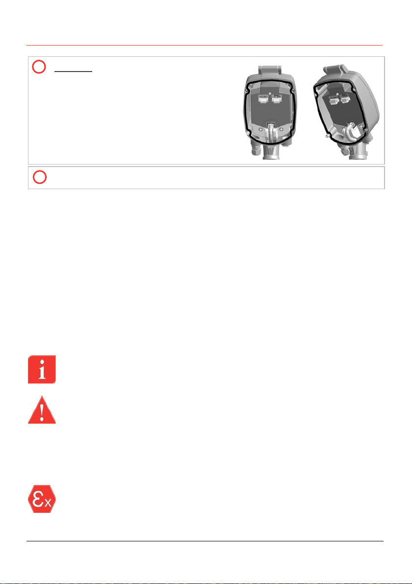
Carefully connect the antenna cable
connector back to the electronic board as
shown.
This connector allows the transmission
signal from the electronic board to the
transducers. Damaged connector or wires
will result with mulfunctioning operation of
the scanner.
Leave the scanner open at this stage in order to complete the wiring.
3.5 Wiring
The 3DLevelScanner can be connected in different modes and configurations for different
external systems such as PLC or DCS and communications on RS-485, ModBus, HART
and also to RS-485 bus converting adapters to communication gateways such as
3DLinkPro for GMS or GPRS data relay and TCP/IP gateway. For in-depth details and
explanations on wiring and communication, refer to page 21: Different Connection
Methods.
Use 8-13mm (20 AWG) diameter cables to ensure proper and effective sealing of the
cable gland entry opening.
Select a cable suitable for application (indoor or outdoor) and safety certified
according to national regulations.
Communications
NOTE: If electromagnetic interference is expected, usage of a screened and
twisted wired cable is recommended for the signal lines, which should be
connected to the ground reference
.
CAUTION: Always observe the following safety instructions:
Connections m
ust be made only in the complete absence of line voltage.
If over
-voltage is expected, overvoltage arresters should be installed.
Use only a safety
-
certified power supply with dual insulation between the primary
and output for powering the unit. The power supply output rating must be limited
to 20
-32VDC, 1A for a single 3DLevelScanner device
, and not to be connected to
a DC distribution network.
In hazardous areas you should take note of the appropriate regulations,
conformity and type of approval certificates of the sensors and power supply
units. Refer to the printed safety manual provided with the ATEX/FM approved
3D
LevelScanner.
7
8
Physical Installation ● Wiring
3DLevelScanner Operating Instructions © 2012 BinMaster all rights reserved 15
Power Supply
For power supply specifications, refer to page 36: Appendix E: Specifications for full
details.
4-20 mA/HART 4-wire: The power supply and signal current inputs must be carried over
two separated pairs.
Connection Procedure
Untighten the four screws of the scanner
housing rear panel and remove the rear
panel. The
screws are of
captive type and
will not fall off.
Loosen the compression nut
of the cable gland entry.
Insert the cable into the scanner through the cable
gland and entry opening.
Remove approximately 10cm
(4 ") of the cable mantle and
strip approximately 1cm (0.4 ")
the edge of each conductor.
Open the terminal block screws located inside the
scanner housing using a thin flat (A3/32") screwdriver.
Insert the wire edges into the terminals according to the
wiring plan detailed next, and fasten the terminal
screws. Gently pull the wires to ensure they are
securely connected.
2
3
4
5
1
Physical Installation ● Wiring
16 3DLevelScanner Operating Instructions © 2012 BinMaster all rights reserved
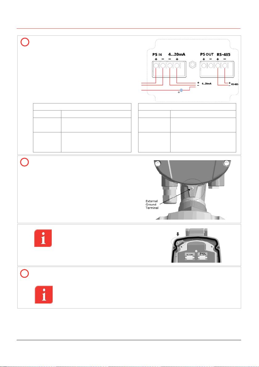
Terminal block wiring plan.
The tables below describes the
connections.
Refer to the following Local Connection
and Multi-Drop Connection drawings for
details.
Left Connector
Right Connector
Ports
Description
Ports
Description
PS IN
⁺ ⁻
Feed in power supply
20 –32DC
PS OUT
⁺ ⁻
No to be used!
4..20mA
⁺ ⁻ 4 - 20 / HART
Communications terminals RS-485
⁺ ⁻
RS-485 / Modbus RTU
Communications
terminals
Connect the external ground terminal with
potential equalization to the external
ground terminal of the scanner, located
as shown.
An internal ground connection is also
possible using the inner connection as
shown.
Tighten the compression nut over the cable gland entry opening. Verify that the
sealing ring completely wraps the cable.
IMPORTANT: Gland compression nut tightening provides good sealing.
It is necessary for the scanner to maintain IP67 requirements, and for
extended scanner lifetime.
6
7
8
Physical Installation ● Wiring
3DLevelScanner Operating Instructions © 2012 BinMaster all rights reserved 17
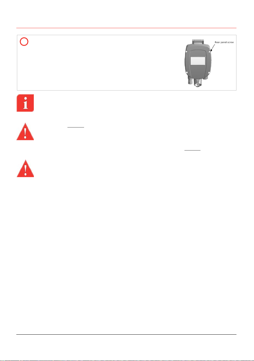
Attach the rear panel back to position at the rear of the
scanner housing and tighten the four screws to secure it in
place, using a 4mm hex key.
The 3DLevelScanner is ready for configuration.
IMPORTANT: Use direct connection between the scanners and the plant
(PLC/SCADA).
IMPORTANT: For a remote connection, use the 3DLinkPro remote connection
module or a local PC/Laptop computer as detailed in the following drawing.
CAUTION: Do not connect the power supply cables to the 4-20mA/HART input,
to the RS-485 ports or to the PS output.
The 3DLevelScanner is not a loop powered device but a 4W device.
The PS ports in the right connector are Power Supply OUT. Do not plug IN power
supply in these ports.
WARNING: The 4-20mA / HART lines should NOT be connected using multidrop.
9
18 3DLevelScanner Operating Instructions © 2012 BinMaster all rights reserved
4First-Time Activation
4.1 Local User Interface
Configuration and adjustment of the 3DLevelScanner must be done using the
3DLevelManager software, with the optional addition of GSM/GPRS communications
using 3DLinkPro. For detailed configuration procedure, refer to the BinMaster
3DLevelManager Software Manual and the 3DLinkPro Manual.
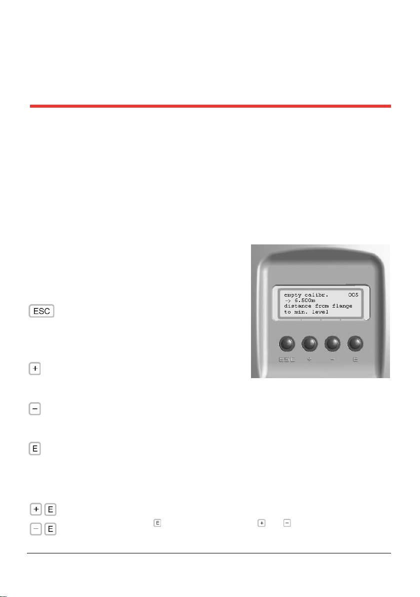
The 3DLevelScanner User Interface
The user interface includes a 4-line LCD display and
the four keys located on the front side of the device,
marked ESC, +, - and E.
Key functions are as follows:
Navigates back within a function menu.
Continous 3 second press exits to the
default screen.
Navigates upwards in the navigation list.
Navigates right within a function.
Navigates downwards in the navigation list.
Navigates left within a function.
Navigates to the right when within a function group.
Stores a value once configured.
The following, simultaneous key-press combinations perform special functions as follows:
Increase/decrease the LCD display intensity.
Press and hold the button, then use the or buttons to increase or
decrease the intensity of the display.
First-Time Activation ● Switching on the scanner
3DLevelScanner Operating Instructions © 2012 BinMaster all rights reserved 19
Operating menu
The operating menu consists of two levels:
Function groups: The scanner functions are organized groups. Available function
groups are: Basic setup, Linearization, Extended Calibration, Output Settings, Display
Settings, Device Info and Device Reset.
Functions: Each function group consists of one or more functions. The functions may
perform different actions or modify scanner setting parameters. Numerical values can
be entered, and parameters can be selected and saved.
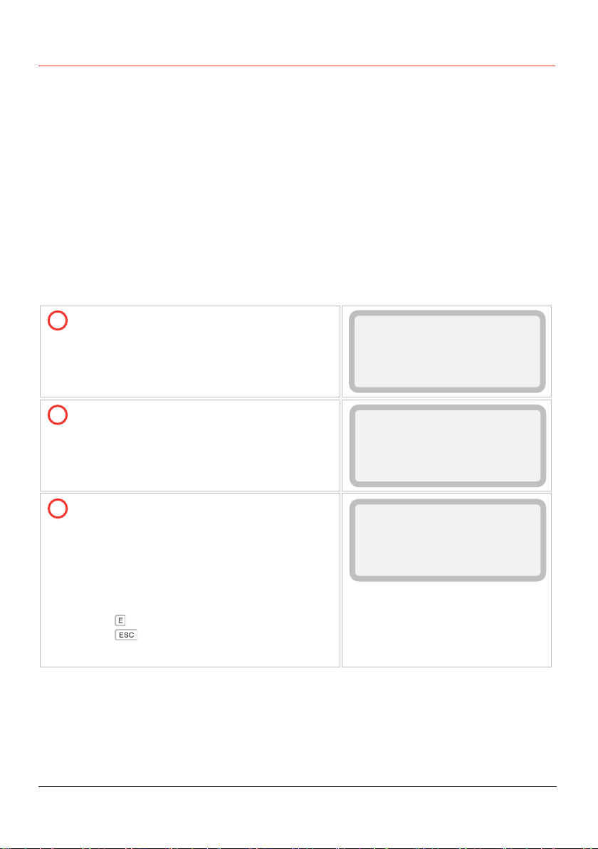
4.2 Switching on the scanner
Once the 3DLevelScanner is connected to the power supply and switched on, it initializes
a self-test which lasts for approximately 30 seconds. When the initialization is complete,
the following content is displayed allowing selecting a language and distance units:
The unit is turned on and is initializing for
about 30 seconds, during which the display
remains blank.
The version screen appears:
The value in <> describes the scanner
model: S, M, MV ot MVL.
FW Ver: firmware version
HW Ver: hardware version
Once the startup process is complete, the
following screen appears showing the
current distance measurement.
The forth line displays the scanner tag
name. By default, when the name has not
been configured yet, this line remains
empty.
Press to return to the Main Menu.
Press for 3 seconds to switch to the
basic measurement screen.
Init. Please wait...
3DLEVELSCANNER <MV>
FW Ver: 03.00.00
HW Ver: 020
Measured Parameter
3.45m Dist.
██████████████████████
test
1
2
3
This manual suits for next models
11
Table of contents
Other Bin Master Measuring Instrument manuals

Bin Master
Bin Master MAXIMA+ Series User manual

Bin Master
Bin Master DPM-400 User manual

Bin Master
Bin Master SMARTBOB TS1 User manual

Bin Master
Bin Master PROCAP I Series User manual

Bin Master
Bin Master 1000 User manual

Bin Master
Bin Master NCR-80 User manual

Bin Master
Bin Master GWR-2000 User manual

Bin Master
Bin Master CNCR-110 User manual

Bin Master
Bin Master DPM-500 User manual

Bin Master
Bin Master BMRX Series User manual


