HB-THERM T24629-X User manual

Temperatur Control Technology
www.hb-therm.ch
M8086-EN 2020-02 1/6
2020-02
Page
Assembly Instructions
M8086-EN
Spare part Sonic transducer (O/ID T24629-X, T26326-X, T25242-X,
T25865-X)
Purpose
Replacement of Sonic transducer (BB 1, BB 2)
Precondition
WARNING!
Danger for unauthorized persons!
Conversion work may only be carried out by
specialist staff who have been trained accordingly.
Therefore:
–Keep unauthorized persons away from the work
area.
NOTE!
Knowledge of the Instruction Manual is a
precondition for carrying out conversion work on
the unit.
Procedure
DANGER!
Danger to life caused by electric current!
Touching conductive parts causes a direct danger
to life.
Therefore:
–For all work on the electrical system, for
maintenance, cleaning or repair work,
disconnect from the mains or disconnect all
phases of the external power supply and secure
them against being switched on again. Check
unit is isolated from power supply.
WARNING!
Danger of crushing due to rolling away or
tipping
With an uneven floor or when the castors are not
locked, there is a danger that the unit tips over or
rolls away causing crushing.
Therefore:
–Only install the unit on an even floor.
–Ensure that the castors are locked.

Assembly Instructions M8086-EN
M8086-EN 2020-02 2/6
1. Proceed as follows in order to cool down the unit and empty
the mould (mould evacuation):
Display menu page Functions.
Select the function Cooling and activate with the key.
If the function Mould evacuation is available, select it and
activate it with the key.
The activated function is indicated with the symbol.
Units HB-100X_4 and HB-100/140/160Z_4 without function
Mould evacuation: Loosen the drain connection (G) slowly until
the unit is depressurized.
2. Main switch off, remove the plug from the mains and empty
the unit.
3. Remove the cover from the unit (see Instruction Manual
Chapter Maintenance).
4. Loosen the screws in the front panel and hinge it down.
Assembly Instructions M8086-EN
M8086-EN 2020-02 3/6
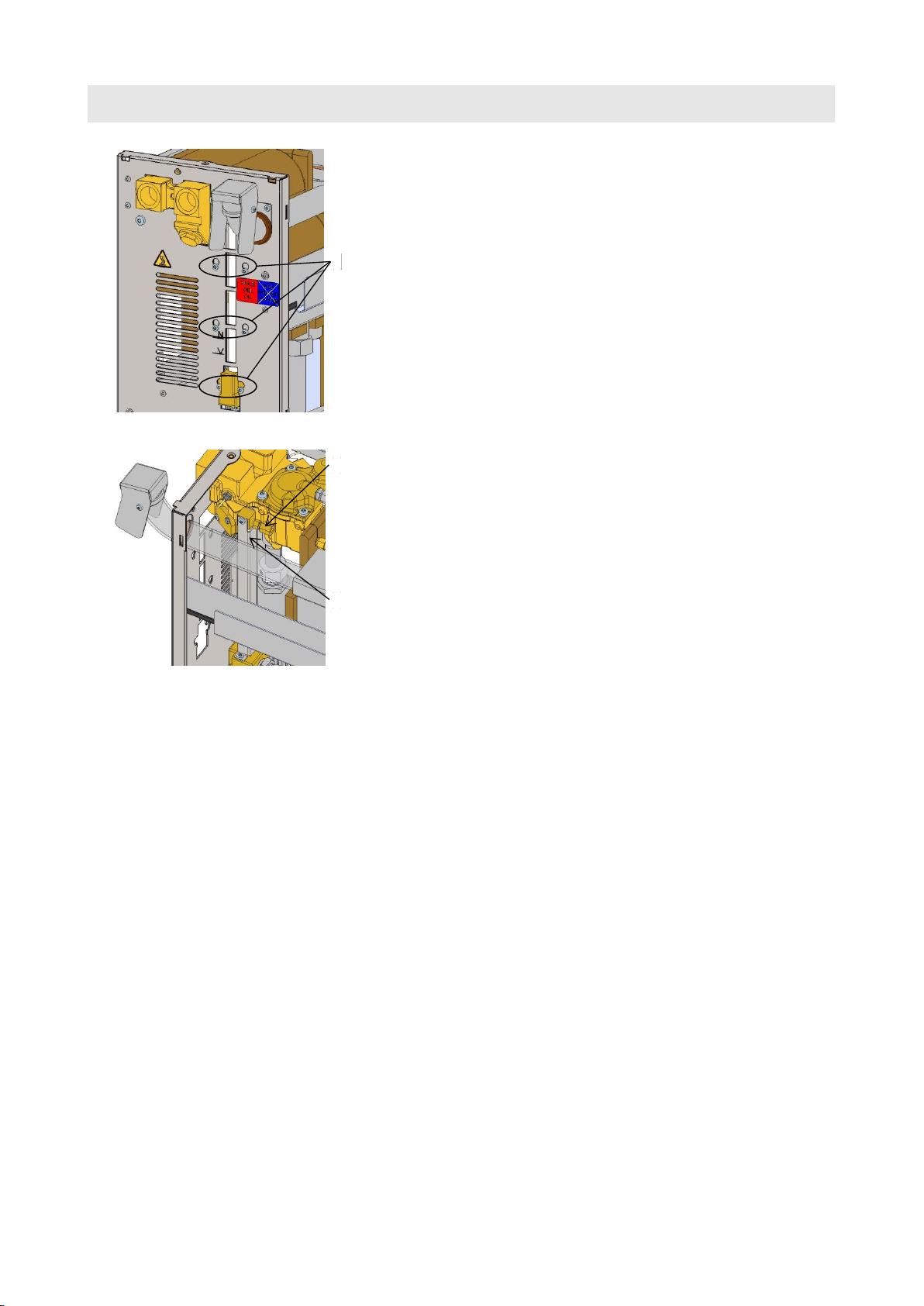
Fig. 1: Removing level indicator
Fig. 2: Pulling out level indicator
Only on T25865-1 and replacement sonic transducer BB 1
5. To enable accessibility to the transducer (BB 1), the level
indicator (10) must be removed. Proceed as follows:
Undo screws on pipe (Label 1 Fig. 2).
Remove 6x screws (Label 2 Fig. 1).
Pull out level indicator (Label 3 Fig. 2) so that accessibility to
the transducer (BB 1) is ensured.
6. Proceed as follows in order to remove the sound transducer
(BB 1, BB 2):
Remove the screws and mounting plate of the sound
transducer.
Remove sound transducer.
Remove O-ring.
Unplug cable of the sound transducer (BB 1, BB 2) on slot
X 53.1 or X 53.2.
7. Proceed as follows to assemble the new sound transducer
(BB 1, BB 2)
Clean installation space of sound transducer, especially groove
for O-ring.
Insert the new O-ring in the groove.
Fit the sound transducer with the mounting plate and screws
carefully.
Transfer the cable labelling of the old sound transducer to the
new sound transducer.
Insert the sound transducer into the corresponding slot at the
X 53.1 or X 53.2.
0
0
2
1
3
Assembly Instructions M8086-EN
M8086-EN 2020-02 4/6
NOTICE!
The 2nd sound transducer should be cleaned, if the
demounted sound transducer is showing dirt on the
side touching the medium.
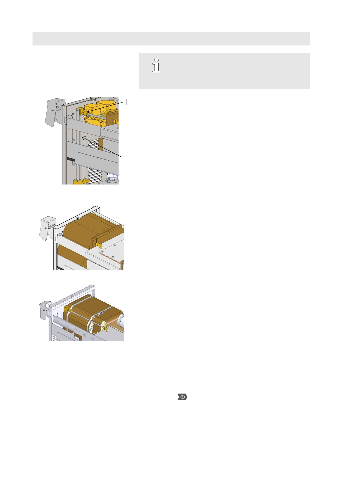
Fig. 3: Mount level indicator
Only on T25865-1 and replacement sonic transducer BB 1
8. To mount the level indicator, proceed as follows:
Push in level indicator (10) (Label 1 Fig. 3).
Mount 6x screws.
Tighten screws on pipe (Label 2 Fig. 3).
Fig. 4: Fitting insulation on 200T2
Fig. 5: Fitting insulation on 250T3
Only on oil units
9. Fit insulation as shown in Fig. 4 or Fig. 5.
10.Close and secure the front panel.
11.Reconnect mains plug and switch on main switch.
12.Press the key to switch on the unit and check it for leaks.
2
1
Assembly Instructions M8086-EN
M8086-EN 2020-02 5/6
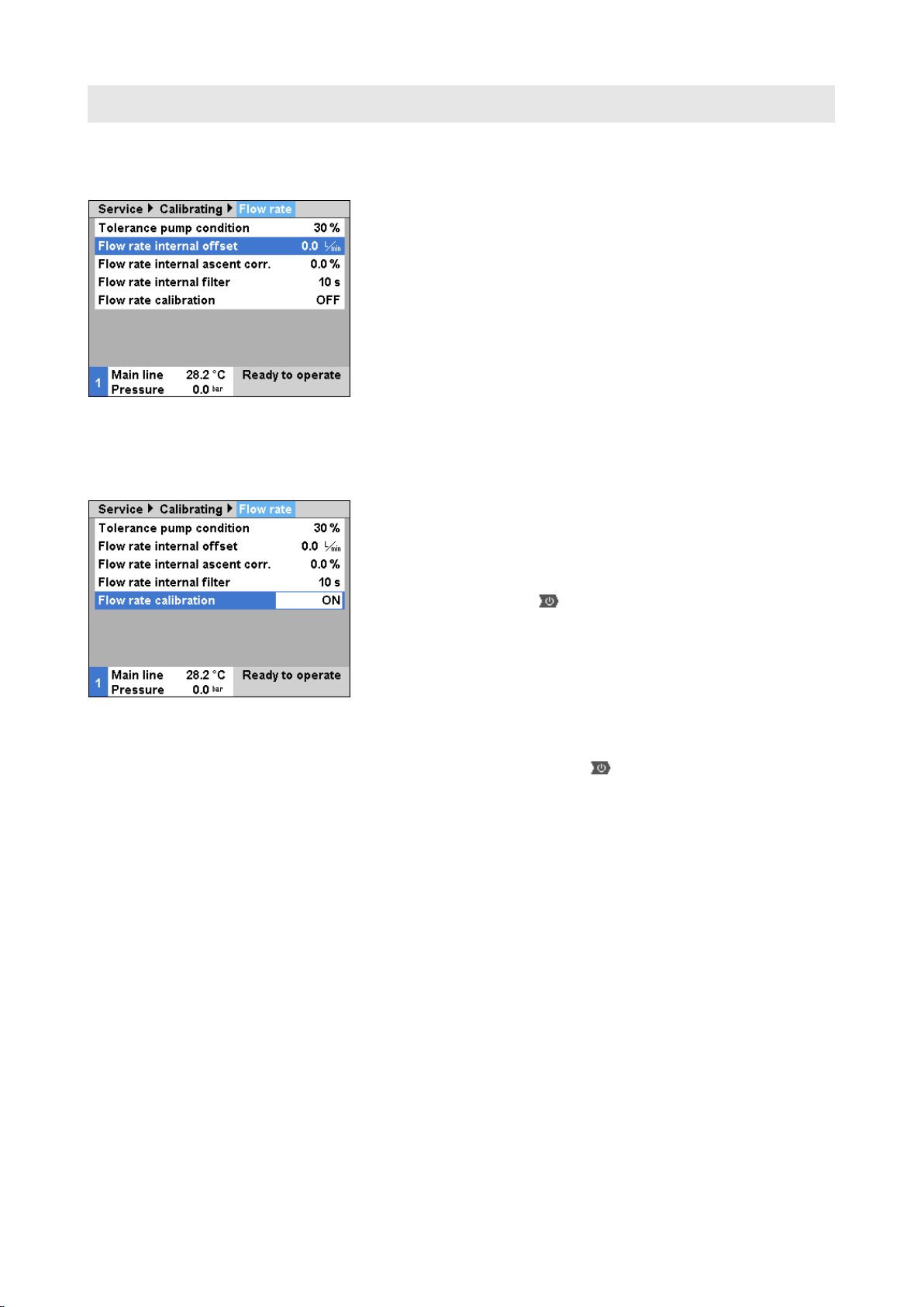
Fig. 6: Calibrating the flow rate
13.Flow rate calibration
(Software versions prior to SW51-1 0849B)
Operate unit in regular mode at 40 °C for at least 10 minutes.
Set Flow rate internal offset parameter in Service \ Calibrating \
Flow rate internally to "5 L/min".
Close shut-off valve between main or return line and wait for
1 minute.
Note current Flow rate.
Set Flow rate internal offset according to the following
calculation:
New Flow rate internal offset = 5 –current Flow rate
Open shut-off valve.
Fig. 7: Calibrating the flow rate
(From software version SW51-1 0849B onwards)
Operate unit in regular mode at 40 °C for at least 10 minutes.
Only for water units:
If available, set Pressure relief with unit OFF parameter in
Setting \ Miscellaneous to "OFF".
Switch off unit using button and wait at least 10 seconds.
Set Flow rate calibration parameter in Service \ Calibrating \
Flow rate internally to "ON".
The flow rate is calibrated automatically.
Only for water units:
If available, set Pressure relief with unit OFF parameter in
Setting \ Miscellaneous to "ON".
Switch on the unit using the key.

Assembly Instructions M8086-EN
M8086-EN 2020-02 6/6
14.Check flow rate calibration:
After calibration, run the unit for at least 5 minutes at 40 °C in
normal mode.
Close shut-off valve between feed and return lines.
Flow rate switches to 0 L/min and alarm indication ‚Flow rate
zero’is given.
NOTE!
The alarm message ‚Flow rate zero’ is delayed in
time.
If this is not the case, repeat the flow rate calibration.
ATTENTION!
Risk of incorrect calibration!
False calibrations can lead to faults witch the unit.
Therefore:
–Check the calibrations.
15.Switch the unit off by press the key.
16.Main switch off.
17.Close the unit correctly again.
Parts list
Pos
Description
O/ID
O/ID
T24629-1
T24629-2
T26326-1
T26326-3
T25242-2
T25865-1
T25865-3
Pcs
Pcs
Pcs
Pcs
Pcs
Pcs
Pcs
01
Sonic transducer water up to 160 °C, 1 m
T27045-1
1
-
-
-
-
-
-
02
Sonic transducer water up to 160 °C, 1,45 m
T27045-3
-
1
-
-
-
-
-
03
Sonic transducer water up to 180 °C, 1 m
T26310-1
-
-
1
-
-
-
-
04
Sonic transducer water up to 180 °C, 1,45 m
T26310-3
-
-
-
1
-
-
-
05
Sonic transducer oil up to 200 °C, 1 m
T26328-1
-
-
-
-
1
-
-
06
Sonic transducer oil up to 200 °C, 1 m
T26082-1
-
-
-
-
-
1
-
07
Sonic transducer oil up to 250 °C, 1,45 m
T26082-3
-
-
-
-
-
-
1
08
Socket 27x14x9 PEEK
T26080
-
-
-
-
-
1
1
09
O-Ring FPM 17x2 mm
T23523
-
-
-
-
1
-
-
10
O-Ring FFKM 17x2 mm
T25429
1
1
1
1
-
2
2
11
Assembly instructions German
M8086-DE
1
1
1
1
1
1
1
12
Assembly instructions English
M8086-EN
1
1
1
1
1
1
1
13
Assembly instructions French
M8086-FR
1
1
1
1
1
1
1
This manual suits for next models
2
Other HB-THERM Transducer manuals


Popular Transducer manuals by other brands

Mianyang Weibo Electronic
Mianyang Weibo Electronic WBI122S01 user manual

APAR
APAR AR553 User instruction

DaytonAudio
DaytonAudio HDN-8 user manual

Licht
Licht MFC-400/I-VAC Technical manual

Camille Bauer
Camille Bauer Gossen MetraWatt SINEAX DME 401 operating instructions

Krell Industries
Krell Industries LAT series owner's manual


