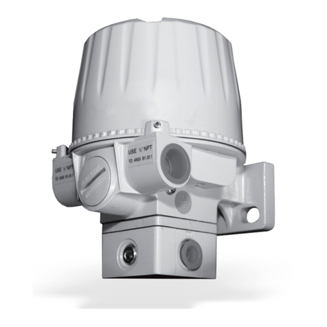
GE T17 User manual

GE
Oil & Gas Flow
916-128 Rev. D
September 2020
Model T17
Ultrasonic Flow Transducer
Installation Guide


www.gemeasurement.com
© Copyright 2020. Baker Hughes Company. This material
contains one or more registered trademark of Baker Hughes
Company and its subsidiaries in one or more countries. All
third-party product and company names are trademarks of
their respective holders.
GE
Oil & Gas
Model T17
Ultrasonic Flow Transducer
Installation Guide
916-128 Rev. D
September 2020

ii
[no content intended for this page]

Model T17 Installation Guide iii
Contents
Chapter 1. Introduction
1.1 Overview. . . . . . . . . . . . . . . . . . . . . . . . . . . . . . . . . . . . . . . . . . . . . . . . . . . . . . . . . . . . . . . . . . . . . . . . . . . . . . . . . . . . . . . . . . . . . . .1
1.2 Transducer Construction. . . . . . . . . . . . . . . . . . . . . . . . . . . . . . . . . . . . . . . . . . . . . . . . . . . . . . . . . . . . . . . . . . . . . . . . . . . . . . . .1
1.3 Certification and Safety Statements . . . . . . . . . . . . . . . . . . . . . . . . . . . . . . . . . . . . . . . . . . . . . . . . . . . . . . . . . . . . . . . . . . . . .2
Chapter 2. Installing the Pipe Nozzles
2.1 Introduction. . . . . . . . . . . . . . . . . . . . . . . . . . . . . . . . . . . . . . . . . . . . . . . . . . . . . . . . . . . . . . . . . . . . . . . . . . . . . . . . . . . . . . . . . . . .3
2.2 Nozzle Installation - Diametrical Path. . . . . . . . . . . . . . . . . . . . . . . . . . . . . . . . . . . . . . . . . . . . . . . . . . . . . . . . . . . . . . . . . . . .4
2.2.1 Identifying the Nozzle Installation Kit Components - Diametrical . . . . . . . . . . . . . . . . . . . . . . . . . . . . . . . . . .5
2.2.2 Selecting and Marking the First Nozzle Location - Diametrical . . . . . . . . . . . . . . . . . . . . . . . . . . . . . . . . . . . . .6
2.2.3 Determining and Marking the Second Nozzle Location - Diametrical . . . . . . . . . . . . . . . . . . . . . . . . . . . . . .8
2.2.4 Installing the First Welding Boss - Diametrical . . . . . . . . . . . . . . . . . . . . . . . . . . . . . . . . . . . . . . . . . . . . . . . . . . .12
2.2.5 Installing the First Nozzle - Diametrical. . . . . . . . . . . . . . . . . . . . . . . . . . . . . . . . . . . . . . . . . . . . . . . . . . . . . . . . . .14
2.2.6 Installing the Second Welding Boss and Nozzle - Diametrical. . . . . . . . . . . . . . . . . . . . . . . . . . . . . . . . . . . . .16
2.2.7 Hot Tapping the Pipe - Diametrical. . . . . . . . . . . . . . . . . . . . . . . . . . . . . . . . . . . . . . . . . . . . . . . . . . . . . . . . . . . . . .17
2.2.8 Cold Tapping the Pipe - Diametrical. . . . . . . . . . . . . . . . . . . . . . . . . . . . . . . . . . . . . . . . . . . . . . . . . . . . . . . . . . . . .17
2.3 Nozzle Installation - MR1 Mid-Radius Path . . . . . . . . . . . . . . . . . . . . . . . . . . . . . . . . . . . . . . . . . . . . . . . . . . . . . . . . . . . . . .18
2.3.1 Identifying the Nozzle Installation Kit Components - MR1 Mid-Radius. . . . . . . . . . . . . . . . . . . . . . . . . . . . .19
2.3.2 Selecting and Marking the First Nozzle Location - MR1 Mid-Radius . . . . . . . . . . . . . . . . . . . . . . . . . . . . . . .20
2.3.3 Determining and Marking the Second Nozzle Location - MR1 Mid-Radius . . . . . . . . . . . . . . . . . . . . . . . . .24
2.3.4 Installing the First Welding Boss - MR1 Mid-Radius . . . . . . . . . . . . . . . . . . . . . . . . . . . . . . . . . . . . . . . . . . . . . .29
2.3.5 Installing the First Nozzle - MR1 Mid-Radius . . . . . . . . . . . . . . . . . . . . . . . . . . . . . . . . . . . . . . . . . . . . . . . . . . . . .32
2.3.6 Installing the Second Welding Boss and Nozzle MR1 Mid-Radius . . . . . . . . . . . . . . . . . . . . . . . . . . . . . . . . .34
2.3.7 Hot Tapping the Pipe - MR1 Mid-Radius . . . . . . . . . . . . . . . . . . . . . . . . . . . . . . . . . . . . . . . . . . . . . . . . . . . . . . . . .35
2.3.8 Cold Tapping the Pipe - MR1 Mid-Radius . . . . . . . . . . . . . . . . . . . . . . . . . . . . . . . . . . . . . . . . . . . . . . . . . . . . . . . .35
2.4 Nozzle Installation - MR2 Mid-Radius Path . . . . . . . . . . . . . . . . . . . . . . . . . . . . . . . . . . . . . . . . . . . . . . . . . . . . . . . . . . . . . .36
2.4.1 Identifying the Nozzle Installation Kit Components - MR2 Mid-Radius. . . . . . . . . . . . . . . . . . . . . . . . . . . . .37
2.4.2 Selecting and Marking the First Nozzle Location - MR2 Mid-Radius . . . . . . . . . . . . . . . . . . . . . . . . . . . . . . .38
2.4.3 Determining and Marking the Second Nozzle Location - MR2 Mid-Radius . . . . . . . . . . . . . . . . . . . . . . . . .42
2.4.4 Installing the First Welding Boss - MR2 Mid-Radius . . . . . . . . . . . . . . . . . . . . . . . . . . . . . . . . . . . . . . . . . . . . . .47
2.4.5 Installing the First Nozzle - MR2 Mid-Radius . . . . . . . . . . . . . . . . . . . . . . . . . . . . . . . . . . . . . . . . . . . . . . . . . . . . .50
2.4.6 Installing the Second Welding Boss and Nozzle MR2 Mid-Radius . . . . . . . . . . . . . . . . . . . . . . . . . . . . . . . . .52
2.4.7 Hot Tapping the Pipe - MR2 Mid-Radius . . . . . . . . . . . . . . . . . . . . . . . . . . . . . . . . . . . . . . . . . . . . . . . . . . . . . . . . .53
2.4.8 Cold Tapping the Pipe - MR2 Mid-Radius . . . . . . . . . . . . . . . . . . . . . . . . . . . . . . . . . . . . . . . . . . . . . . . . . . . . . . . .53
Chapter 3. Installing an Isolation Valve
3.1 Introduction. . . . . . . . . . . . . . . . . . . . . . . . . . . . . . . . . . . . . . . . . . . . . . . . . . . . . . . . . . . . . . . . . . . . . . . . . . . . . . . . . . . . . . . . . . .55
3.2 Valve Installation for 3-inch Flanges . . . . . . . . . . . . . . . . . . . . . . . . . . . . . . . . . . . . . . . . . . . . . . . . . . . . . . . . . . . . . . . . . . . .55

Contents
iv Model T17 Installation Guide
Chapter 4. Inserting T17 Transducers into the Pipe
4.1 Introduction. . . . . . . . . . . . . . . . . . . . . . . . . . . . . . . . . . . . . . . . . . . . . . . . . . . . . . . . . . . . . . . . . . . . . . . . . . . . . . . . . . . . . . . . . . .57
4.2 Inserting Transducers Using the Insertion Mechanism. . . . . . . . . . . . . . . . . . . . . . . . . . . . . . . . . . . . . . . . . . . . . . . . . . .57
4.2.1 Preparing for Installation. . . . . . . . . . . . . . . . . . . . . . . . . . . . . . . . . . . . . . . . . . . . . . . . . . . . . . . . . . . . . . . . . . . . . . .57
4.2.2 Mounting the Insertion Mechanism . . . . . . . . . . . . . . . . . . . . . . . . . . . . . . . . . . . . . . . . . . . . . . . . . . . . . . . . . . . . .58
4.2.3 Aligning the Downstream Transducer for Extended Range Installations . . . . . . . . . . . . . . . . . . . . . . . . . .65
4.3 Connecting an XAMP . . . . . . . . . . . . . . . . . . . . . . . . . . . . . . . . . . . . . . . . . . . . . . . . . . . . . . . . . . . . . . . . . . . . . . . . . . . . . . . . . .69
Chapter 5. Maintaining the T17 Transducers
5.1 Removing Transducers . . . . . . . . . . . . . . . . . . . . . . . . . . . . . . . . . . . . . . . . . . . . . . . . . . . . . . . . . . . . . . . . . . . . . . . . . . . . . . . .75
5.2 Using the Insertion Mechanism . . . . . . . . . . . . . . . . . . . . . . . . . . . . . . . . . . . . . . . . . . . . . . . . . . . . . . . . . . . . . . . . . . . . . . . .75
Chapter 6. Specifications
6.1 T17 Transducer Physical Specifications. . . . . . . . . . . . . . . . . . . . . . . . . . . . . . . . . . . . . . . . . . . . . . . . . . . . . . . . . . . . . . . . .79
6.2 T17 Transducer Certifications . . . . . . . . . . . . . . . . . . . . . . . . . . . . . . . . . . . . . . . . . . . . . . . . . . . . . . . . . . . . . . . . . . . . . . . . . .79

Model T17 Installation Guide v
Preface
Information Paragraphs
Note: These paragraphs provide information that provides a deeper understanding of the situation, but is not
essential to the proper completion of the instructions.
IMPORTANT: These paragraphs provide information that emphasizes instructions that are essential to proper setup of
the equipment. Failure to follow these instructions carefully may cause unreliable performance.
Safety Issues
Auxiliary Equipment
Local Safety Standards
The user must make sure that he operates all auxiliary equipment in accordance with local codes, standards,
regulations, or laws applicable to safety.
Working Area
CAUTION! This symbol indicates a risk of potential minor personal injury and/or severe damage to
the equipment, unless these instructions are followed carefully.
WARNING! This symbol indicates a risk of potential serious personal injury, unless these instructions
are followed carefully.
WARNING! It is the responsibility of the user to make sure all local, county, state and national codes,
regulations, rules and laws related to safety and safe operating conditions are met for each
installation.
WARNING! For installations in potentially hazardous areas, be sure to read the Certification and
Safety Statements document at the end of this manual before beginning the installation.
WARNING! Auxiliary equipment may have both manual and automatic modes of operation. As
equipment can move suddenly and without warning, do not enter the work cell of this equipment
during automatic operation, and do not enter the work envelope of this equipment during manual
operation. If you do, serious injury can result.
WARNING! Make sure that power to the auxiliary equipment is turned OFF and locked out before
you perform maintenance procedures on the equipment.

Preface
vi Model T17 Installation Guide
Qualification of Personnel
Make sure that all personnel have manufacturer-approved training applicable to the auxiliary equipment.
Personal Safety Equipment
Make sure that operators and maintenance personnel have all safety equipment applicable to the auxiliary equipment.
Examples include safety glasses, protective headgear, safety shoes, etc.
Unauthorized Operation
Make sure that unauthorized personnel cannot gain access to the operation of the equipment.
Environmental Compliance
Waste Electrical and Electronic Equipment (WEEE) Directive
GE Measurement & Control is an active participant in Europe’s Waste Electrical and Electronic Equipment (WEEE)
take-back initiative, directive 2012/19/EU.
The equipment that you bought has required the extraction and use of natural resources for its production. It may
contain hazardous substances that could impact health and the environment.
In order to avoid the dissemination of those substances in our environment and to diminish the pressure on the natural
resources, we encourage you to use the appropriate take-back systems. Those systems will reuse or recycle most of the
materials of your end life equipment in a sound way.
The crossed-out wheeled bin symbol invites you to use those systems.
If you need more information on the collection, reuse and recycling systems, please contact your local or regional
waste administration.
Visit https://www.gemeasurement.com/environmental-health-safety-ehs for take-back instructions and more
information about this initiative.
RoHS Compliance
This equipment is fully compliant with the RoHS regulatory requirements.

Model T17 Installation Guide 1
Chapter 1. Introduction
1.1 Overview
The T17 ultrasonic flow transducer is used exclusively with the GE line of ultrasonic flowmeters. These transducers
measure the flow rate of sonically-conductive gases through pipes having diameters between 12 in. (305 mm) and
120 in. (3000 mm). This manual provides details on the following topics:
•Transducer construction
•Nozzle installation
•Transducer installation
•Maintenance
•Specifications
Note: For installation on pipes ranging from 4 to 12 in. (100 to 300 mm), or for using the BIAS 90° configuration,
please see the GE #916-117 Installation Guide.
1.2 Transducer Construction
Each T17 transducer assembly (see Figure 1 below) consists of the following components:
•A fully sealed, welded, all metal body made from grade 2 titanium as standard
•A transducer head that consists of piezoelectric elements wired to the BNC connector
•A BNC style connector for use in connecting the transducer to the flowmeter
The T17 transducer is available in standard lengths of 33 in. (840 mm) to 60 in. (1500 mm) and with either a 180oor
174o angled head.
Figure 1: General T17 Transducer (180oHead)
Transducer Head
Metallic Body
BNC Connector

Chapter 1. Introduction
2Model T17 Installation Guide
1.3 Certification and Safety Statements
To maintain DEKRA certification, the transducer is provided with a ATEX and IECEx certified compression fitting
and/or adapter of either thread M25 X 1.5 (material: brass) or ¾” NPT (material: 316 SS), both with tube size of 0.50”
O.D. For example: Tyco part number 496SSGL34Ex ATEX certified under BASEEFA 08ATEX0327X and IECEx
BAS08.0107X, Peppers adapter part number ARB/NP/075NPT/M20 ATEX certified under SIRA09ATEX1322X or
SIRA09ATEX4323X and IECEx SIR09.0121X and reducer Capri part number 740724 ATEX certified under
LCIO8ATEX6085X and IECEx LC018.0035X or equivalent parts. ATEX/IECEx certified enclosure, Type Ex d IIC.
For example: International Metal Engineering PTE Limited (IME) Type 8080, 8075, 8066 or 7080 certified under
SIRA 07ATEX1331U and IECEx SIR 07.0111U or equivalent that complies with EN 60079-0:2012/IEC 60079-0:2011
and EN 60079-1:2007/IEC 60079-1:2007. For example: Cortem SL-26.1N certified under CESI 03ATEX032U or
equivalent. A certified metric-to-NPT adapter (material: brass) may be used in addition to the compression fitting in
applicable configurations. Both fitting and adapter to comply with EN 60079-0:2012/ IEC 60079-0:2011 and EN
60079-1:2007/ IEC 60079-1:2007 for Ex d IIC. For electrical connection, the transducer must be mounted into a
certified metal enclosure with type of protection flameproof enclosure “D”, complying with EN 60079-1:2007 and IEC
60079-1:2007 Ex d IIC. Measures must be taken to ensure a good electrical contact and to prevent the threads from
self-loosening. The compression fitting is suitable for temperatures –60°C to 250°C.

Model T17 Installation Guide 3
Chapter 2. Installing the Pipe Nozzles
2.1 Introduction
Before the T17 transducers can be installed into the pipe, you will need to install pipe nozzles. Nozzles may be installed
as part of a fabricated spoolpiece, or by using a hot or cold tapping process with a GE Nozzle Installation Kit.
IMPORTANT: These procedures only apply if you are using a Nozzle Installation Kit. If you are tapping the pipe
without using a Nozzle Installation Kit, refer to the supplied drawings in your shipment. This procedure
is written and illustrated for installations on horizontal pipes. However, the procedure is the same for
vertical pipe installations.
This chapter describes how to install pipe nozzles in the two available flow range options:
•Standard flow range operation of 0.1 to 328 f/s (0.03 to 100 m/s):
This configuration uses two 180° head T17 transducers.
•Extended flow range operation of 0.1 to 394 f/s (0.03 to 120 m/s):
This configuration uses one 180° head T17 transducer and one 174° head T17 transducer.
Either of the above flow range options may be used in one of three possible signal path configurations (Figure 2 below
illustrates the mirror-image difference between the nozzles for the two mid-radius configurations):
•“Nozzle Installation - Diametrical Path” on page 4
•“Nozzle Installation - MR1 Mid-Radius Path” on page 18
•“Nozzle Installation - MR2 Mid-Radius Path” on page 36
Figure 2: Top View of Mid-Radius Nozzles (MR1 on Left, MR2 on Right)
CAUTION! The components in your Nozzle Installation Kit have been designed for one specific
signal path configuration only. You must properly identify your kit components and then follow only
those nozzle installation instructions in the appropriate section.

Chapter 2. Installing the Pipe Nozzles
4Model T17 Installation Guide
2.2 Nozzle Installation - Diametrical Path
A diametrical signal path is one in which the ultrasonic signal between the two transducers travels along a diameter of
the pipe (see Figure 3 below). Typically, the transducers are located at the 3 o’clock and 9 o’clock positions, when
viewed from the downstream end of the pipe.
Figure 3: Diametrical Path Configuration
The Diametrical path nozzle installation procedure includes the following steps:
1. “Identifying the Nozzle Installation Kit Components - Diametrical” on page 5
2. “Selecting and Marking the First Nozzle Location - Diametrical” on page 6
3. “Determining and Marking the Second Nozzle Location - Diametrical” on page 8
4. “Installing the First Welding Boss - Diametrical” on page 12
5. “Installing the First Nozzle - Diametrical” on page 14
6. “Installing the Second Welding Boss and Nozzle - Diametrical” on page 16
7. Proceed to one of the following:
•“Hot Tapping the Pipe - Diametrical” on page 17
•“Cold Tapping the Pipe - Diametrical” on page 17
End View - Downstream

Model T17 Installation Guide 5
Chapter 2. Installing the Pipe Nozzles
2.2.1 Identifying the Nozzle Installation Kit Components - Diametrical
The Nozzle Installation Kit includes all of the components required for your diametrical configuration. Before
proceeding, you must identify these parts and verify that they are the correct parts for your installation.
The Nozzle Installation Kit should contain the following items:
•2 Nozzles (if purchased)
•2 Welding Bosses
•1 Jig
•1 Threaded Rod (1 in. diameter), with Washer and Nut
IMPORTANT: You will need to supply eight 5/8” studs with two nuts each (for 3”x 150# flanges), or eight 3/4” studs
with two nuts each (for 3”x 300# flanges).
Use Figure 4 below to help identify each component.
Figure 4: Components in Nozzle Installation Kit
Welding Boss
Nozzle
Jig
Threaded Rod
with Washer and Nut

Chapter 2. Installing the Pipe Nozzles
6Model T17 Installation Guide
2.2.1 Identifying the Nozzle Installation Kit Components - Diametrical (cont.)
Check the etched markings on the welding boss, as illustrated in Figure 5 below. The diametrical path code, the pipe
OD and the mounting angle are engraved on the bosses.
Figure 5: Welding Boss Etching
2.2.2 Selecting and Marking the First Nozzle Location - Diametrical
CAUTION! Before proceeding, be certain that these values match your intended installation and
that the etched markings are the same on both bosses
CAUTION! Correct nozzle alignment is critical to the accurate operation of the Flowmeter. Therefore,
all marking, positioning and welding operations must be carried out with the utmost attention to
accuracy. The centerline of each nozzle must form an angle of 45° ±1° with the centerline of the pipe.
The centerlines of the two nozzles must form an angle of 180° ±1° with each other, and the points
where the two nozzle centerlines intersect the pipe centerline must be within ±1/16” (±1.6 mm) of
each other. When the nozzle installation is complete, the raised faces of the two flanges must be
parallel to each other.
WARNING! All hole cutting in live process piping must be performed using hot tapping equipment
(see “Hot Tapping the Pipe - Diametrical” on page 17).
Code for Diametrical Path Pipe O.D.
Mounting
Angle

Model T17 Installation Guide 7
Chapter 2. Installing the Pipe Nozzles
2.2.2 Selecting and Marking the First Nozzle Location - Diametrical (cont.)
To mark the first nozzle location, complete the following steps:
1. For optimum performance, you should select a location that has at least 20 pipe diameters of straight,
undisturbed flow upstream and 10 pipe diameters of straight, undisturbed flow downstream from the
measurement point (see Figure 6 below). Undisturbed flow means avoiding sources of turbulence such as
valves, flanges, elbows, swirl and disturbed flow profiles.
Figure 6: Diametrical Nozzle Locations
2. We recommend that you install the nozzles on a diameter as near as possible to the horizontal plane
(i.e., 3 o’clock and 9 o’clock positions) for a horizontal pipe.
Note: If you cannot find a proper location, please consult with GE Flow Application engineering.
3. At the 3 o’clock position, center punch the pipe to mark the position for the center of the first nozzle, as shown
in Figure 7 below.
Figure 7: Mark First Nozzle Location
FLOW
NOZZLE
2 PLACES
10D
20D
D
45°
TOP VIEW
END VIEW
TOP
Side View

Chapter 2. Installing the Pipe Nozzles
8Model T17 Installation Guide
2.2.2 Selecting and Marking the First Nozzle Location - Diametrical (cont.)
4. Spray the area around the first nozzle location mark with a marking dye product. Using a metal straight edge,
scribe 6” long vertical and a horizontal lines that intersect at the center punch mark (see Figure 8 below).
Figure 8: First Nozzle Scribe Lines
2.2.3 Determining and Marking the Second Nozzle Location - Diametrical
To mark the second nozzle location, complete the following steps:
1. The location for the second nozzle is typically a distance equal to one pipe outside diameter along the pipe
from the first nozzle location and on the opposite side of the pipe (i.e., 180°
around). Spray this area with a
marking dye product.
Note: For angles other than 45°, the distance is equal to the pipe OD times the tangent of the installation angle.
2. Due to the possible variation in OD of the pipe, measure the outside diameter of the pipe at four locations
between the nozzle centers (see Figure 9 below). Then, calculate the average OD from these measurements.
Figure 9: Multiple OD Measurements
Side View
D1 D2 D3 D4
Side View

Model T17 Installation Guide 9
Chapter 2. Installing the Pipe Nozzles
2.2.3 Determining and Marking the Second Nozzle Location - Diametrical (cont.)
3. Using a roll of polyester film (or equivalent), cut a strip of film with the following width and length:
IMPORTANT: Ensure that the sides of the film are cut parallel to each other.
•Width: equal to the average outside diameter calculated in Step 2 on the previous page.
•Length: equal to 4 times the average outside diameter of the pipe.
Figure 10: Polyester Film Dimensions
4. Wrap the strip of film around the pipe with one edge running along the vertical scribe line at the first nozzle
location. Make sure the strip overlaps squarely around the pipe and mark the overlap position of the strip, as
shown in Figure 11 below. This equals the circumference of the pipe.
Figure 11: Polyester Film Overlap Mark
Average
O.D.
4 x O.D.
Side View
Overlap Mark

Chapter 2. Installing the Pipe Nozzles
10 Model T17 Installation Guide
2.2.3 Determining and Marking the Second Nozzle Location - Diametrical (cont.)
5. Remove the strip of film and fold it as shown in Figure 12 below to determine the position which is
diametrically opposite the overlap position when the film is reapplied to the pipe.
Figure 12: Folding the Film
6. Mark the outside of the fold for reference, as shown in Figure 13 below.
Figure 13: Marking the Film
7. Place the strip of film back on the pipe. This time, line up the overlap mark with the horizontal and vertical
scribe lines (see Figure 14 below). Again, make sure you wrap the strip of film squarely around the pipe.
Figure 14: Placing the Film on the Pipe
Overlap Mark Fold to Here
Mark the Edge
Overlap Mark
First Edge
Side View

Model T17 Installation Guide 11
Chapter 2. Installing the Pipe Nozzles
2.2.3 Determining and Marking the Second Nozzle Location - Diametrical (cont.)
8. The new position of the center of the second nozzle is now identified as the intersection of the fold line and the
second edge of the strip of film (see Figure 15 below). Center punch this location prior to removing the film.
Figure 15: Center Punch the Second Nozzle Location
9. Remove the film from the pipe.
10. Scribe 6” long vertical and horizontal lines that intersect at the center-punch mark (see Figure 16 below).
Figure 16: Making Scribe Lines
Fold Mark
Side View
Punch Here
Second Edge
Scribe Lines
Side View

Chapter 2. Installing the Pipe Nozzles
12 Model T17 Installation Guide
2.2.4 Installing the First Welding Boss - Diametrical
To install the first welding boss, complete the following steps:
1. Before welding the first boss, you must add another scribe line to the pipe, known as the oblique center line.
The oblique center line compensates for the slope or oblique angle of the boss. The oblique center line is offset
from the true vertical center scribe line marked earlier by a distance X, which is dependent on the pipe outside
diameter and the welding boss diameter as follows:
where, D = pipe outside diameter
d = welding boss outside diameter (1.660 in.)
Using the above equation, values of Xfor some common pipe sizes were calculated and are listed in Table 1 below.
2. Scribe the oblique center line on your pipe at the calculated distance from the true center line for your pipe
size. The oblique center line should be marked on the side of the true center line that is closer to the second
nozzle location, as shown in Figure 17 below.
Figure 17: Scribing the Oblique Center Line
Table 1: X Values for Common Pipe Sizes
Pipe OD X Dimension
NPS (inches) DN (mm) inches mm
12 300 0.058 1.37
14 350 0.049 1.24
16 400 0.043 1.09
18 450 0.038 0.97
20 500 0.035 0.89
22 600 0.031 0.81
24 650 0.029 0.74
26 700 0.027 0.68
XD2⁄d2⁄
sin-1 dD⁄()[]tan
-----------------------------------------
–=
True Center Line Oblique Center Line
Side View
Table of contents
Other GE Transducer manuals
Popular Transducer manuals by other brands

Balluff
Balluff BTL5-C/E1 Series Condensed guide

Camille Bauer
Camille Bauer 542-41210 operating instructions

Simrad
Simrad ES38-12 - REV C datasheet

Humminbird
Humminbird transducer manual

Honeywell
Honeywell PX2 Series installation instructions

Airmar
Airmar P58 Owner's guide & installation instructions

Humminbird
Humminbird 531392-1 B installation manual

S+S Regeltechnik
S+S Regeltechnik PREMASGARD SHD operating instructions

ITR
ITR SEM SC11 User manual and technical documentation

S+S Regeltechnik
S+S Regeltechnik PREMASGARD ALD Operating Instructions, Mounting & Installation

Ametek
Ametek 742R Operation, maintenance, and installation instructions

CARLO GAVAZZI
CARLO GAVAZZI DCT1 user manual