HBM VKK2R-8 DIGITAL User manual
A1144-3.0 en/de
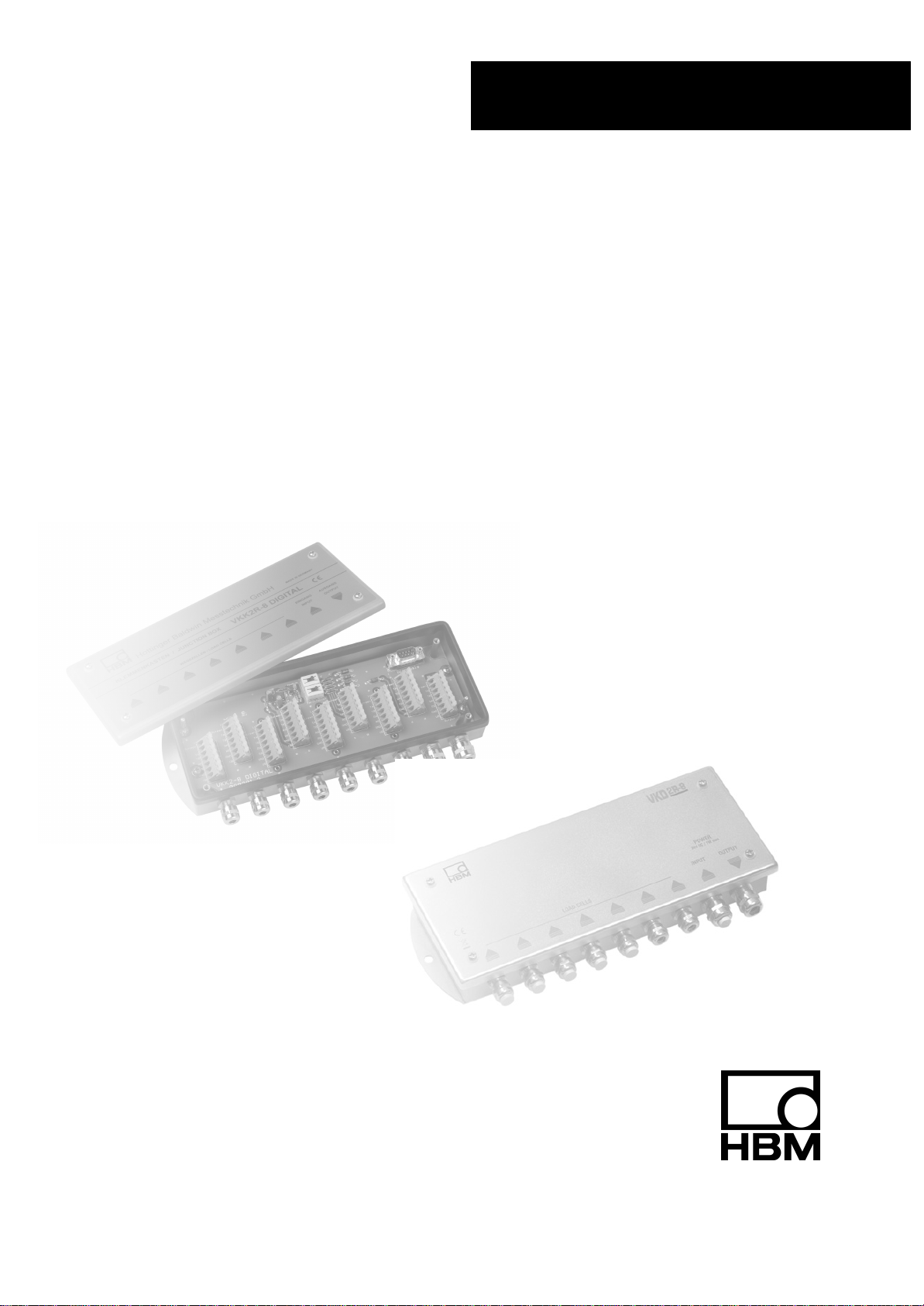
Junction box
Klemmenkasten
VKK2R-8 DIGITAL,
VKD2R-8
Mounting instructions
Montageanleitung
VKK2R-8 DIGITAL
VKD2R-8

2VKK2R-8 DIGITAL, VKD2R-8
HBM A1144-3.0 en/de/fr
Contents Page
Safety instructions 3. . . . . . . . . . . . . . . . . . . . . . . . . . . . . . . . . . . . . . . . . . . . . . . .
1 Introduction and appropriate use 6. . . . . . . . . . . . . . . . . . . . . . . . .
2 Mechanical construction 7. . . . . . . . . . . . . . . . . . . . . . . . . . . . . . . . .
2.1 Mounting 8. . . . . . . . . . . . . . . . . . . . . . . . . . . . . . . . . . . . . . . . .
3 Electrical connection 9. . . . . . . . . . . . . . . . . . . . . . . . . . . . . . . . . . . .
3.1 Cable connection 9. . . . . . . . . . . . . . . . . . . . . . . . . . . . . . . . .
3.2 Clamp connection 10. . . . . . . . . . . . . . . . . . . . . . . . . . . . . . . . .
3.3 Power supply 11. . . . . . . . . . . . . . . . . . . . . . . . . . . . . . . . . . . . .
3.4 Connection to a computer 11. . . . . . . . . . . . . . . . . . . . . . . . . .
3.5 RS-485 4-wire bus 13. . . . . . . . . . . . . . . . . . . . . . . . . . . . . . . .
3.6 RS-485 2-wire bus 14. . . . . . . . . . . . . . . . . . . . . . . . . . . . . . . .
3.7 Connecting VKD2R-8 with DIS2116 16. . . . . . . . . . . . . . . . . .
4 VK... Specifications 17. . . . . . . . . . . . . . . . . . . . . . . . . . . . . . . . . . . .
3
VKK2R-8 DIGITAL, VKD2R-8
HBMA1144-3.0 en/de/fr
NOTE
These mounting instructions describe VKK2R−8 and VKD2R−8 junction
boxes. The design and handling of both devices is absolutely identical. The
type designation is abbreviated to VK... in this document.
Safety instructions
Appropriate use
The junction box is to be used exclusively for interconnecting the interfaces,
the power supply and the bus termination. Use for any purpose other than the
above shall be deemed to be not in accordance with the regulations.
In the interests of safety, the junction box should only be used as described in
the Mounting Instructions. It is also essential to comply with the legal and
safety requirements for the application concerned during use. The same
applies to the use of accessories.
The junction box is not a safety element as defined under Appropriate use.
For safe and trouble-free operation, this junction box must not only be
correctly transported, stored, sited and installed, but must also be carefully
operated and maintained.
General dangers of failing to follow the safety instructions
The junction box is a state of the art unit and as such is fail-safe. The junction
box may give rise to further dangers if it is inappropriately installed and
operated by untrained personnel.
Any person instructed to carry out installation, commissioning, maintenance or
repair of a junction box must have read and understood the Mounting
Instructions and in particular the technical safety instructions.
Symbol:
Meaning: CE mark
The CE mark enables the manufacturer to guarantee that the product
complies with the requirements of the relevant EC guidelines. Please find the
Declaration of Conformity under www.hbm.com.
4VKK2R-8 DIGITAL, VKD2R-8
HBM A1144-3.0 en/de/fr
Remaining dangers
The scope of supply and list of components provided with the junction box
cover only part of the scope of connection technique. In addition, equipment
planners, installers and operators should plan, implement and respond to the
safety engineering considerations of connection technique in such a way as to
minimize remaining dangers. Prevailing regulations must be complied with at
all times. There must be reference to the remaining dangers connected with
connection technique.
Symbol: NOTE
Refers to the fact that important information is being given about the product
or its use.
Unauthorized conversions and modifications are prohibited
The junction box must not be modified from the design or safety engineering
point of view except with our express agreement. Any modification shall
exclude all liability on our part for any resulting damage.
Qualified personnel
The junction box is only to be installed by qualified personnel strictly in
accordance with the technical data and with the rules and safety regulations
which follow. It is also essential to comply with the legal and safety
requirements for the application concerned. The same applies to the use of
accessories.
Qualified personnel means persons entrusted with the installation, assembly,
commissioning and operation of the product who possess the appropriate
qualifications for their function.
Conditions on site
Do not allow the junction box to become dirty or damp.
Maintenance
The junction box is designed to provide degree of protection IP65 (dust
protection, protection against water jets). You must make regular checks to
ensure that the rubber seal in the cover and the screw connections is not
leaking.
Accident prevention
The relevant accident prevention regulations must be taken into
consideration.
5
VKK2R-8 DIGITAL, VKD2R-8
HBMA1144-3.0 en/de/fr
NOTE
Neither the design of the device nor any technical safety aspects may be
modified without the express permission of Hottinger Baldwin Messtechnik
GmbH. Any modification excludes Hottinger Baldwin Messtechnik GmbH from
any and all liability for any damage resulting therefrom.
It is strictly forbidden to carry out any repairs and soldering work on the
motherboards or to replace any components. Repairs may only be carried out
by persons authorized thereto by Hottinger Baldwin Messtechnik GmbH.
•During installation and when connecting the cables, take action to prevent
electrostatic discharge as this may damage the electronics.
•The required power supply is an extra-low voltage (6...30 V) with safe
disconnection from the mains.
•When connecting additional devices, comply with the safety requirements
for electrical measurement, control, regulatory and laboratory equipment
(EN61010).
•All the interconnecting cables must be screened cables. The screen must
be connected extensively to ground on both sides.
This manual suits for next models
1
Table of contents
Languages:


