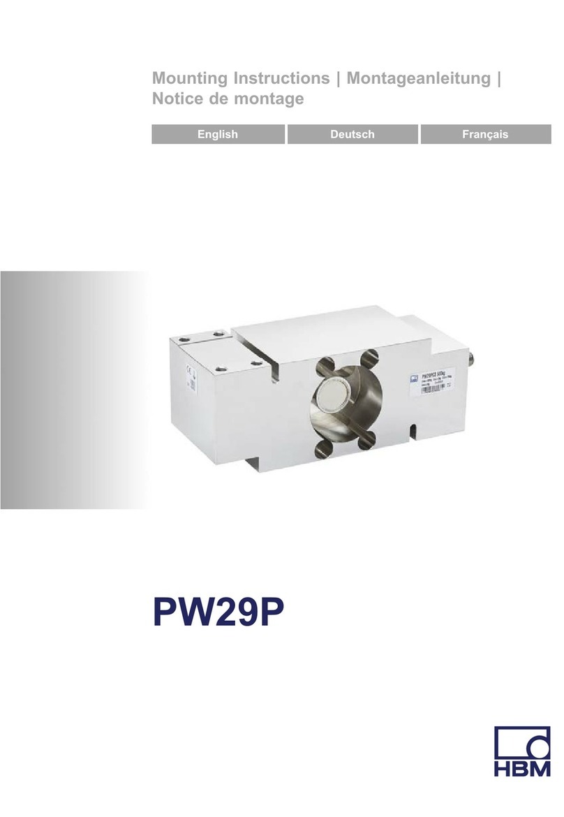
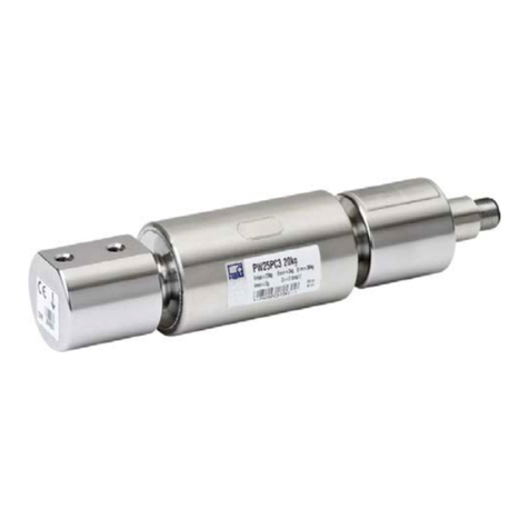
HBM PWSE User manual

A3361-1.0 en/de/fr
Single point load cells
Plattformwägezellen
Pesons plateforme
PWSE
Mounting Instructions
Montageanleitung
Notice de montage

English Page 3 ... 13................................................
Deutsch Seite 14 ... 24..............................................
Français Page 25 ... 32..............................................

3
PWSE
A3361-1.0 en/de/fr HBM
Contents Page
English
Safety instructions 4..............................................
1 Markings used 7...............................................
1.1 Symbols on the load cell 7..................................
1.2 The markings used in this document 7........................
2 Conditions on site 8...........................................
2.1 Protection against corrosion 8...............................
2.2 Deposits 8................................................
3 Mechanical installation 9.......................................
3.1 Important precautions during installation 9....................
3.2 Mounting 9...............................................
4 Electrical connection 11.........................................
4.1 Connection with six‐wire configuration 11......................
4.2 Connection with four‐wire configuration 11.....................
4.3 Shortening the cable 12.....................................
4.4 Cable extension 12.........................................
4.5 EMC protection 12..........................................
5 Specifications 14...............................................
6 Dimensions 15.................................................

PWSE
4
A3361-1.0 en/de/frHBM
Safety instructions
Proper use
Load cells of the PWSE type series are designed for technical weighing
applications within the load limits detailed in the specifications. Any other use
is not the designated use.
The load cells may only be installed by qualified personnel in compliance with
the specifications and with the safety requirements and regulations of these
mounting instructions. It is also essential to observe the applicable legal and
safety regulations for the application concerned. The same applies to the use
of accessories.
Load cells are not intended for use as safety components. Please also refer to
the section: “Additional safety precautions". Proper and safe operation of the
load cells requires proper transportation, correct storage, siting and mounting,
and careful operation.
Loading capacity limits
The data in the technical data sheet must be complied with when using the
load cells. In particular, the respective maximum loads specified must never
be exceeded. The following limits set out in the specifications must not be
exceeded, e.g.:
Limit load
Limit load at max. eccentricity
Limit lateral loading
Breaking loads
Temperature limits
Limits of electrical loading capacity
Note that, when several load cells are installed in a scale, there is not always
an even distribution of load on the individual load cells.
Use as a machine element
The load cells can be used as machine elements. When used in this manner,
it must be noted that, to favor greater sensitivity, the load cell is not designed
with the safety factors usual in mechanical engineering. Please refer here to
the section “Loading capacity limits" and to the specifications.
Accident prevention
The prevailing accident prevention regulations must be taken into account,
even though the maximum capacity values in the destructive range are well in
excess of the full scale value.

5
PWSE
A3361-1.0 en/de/fr HBM
Additional safety precautions
Load cells cannot (as passive transducers) implement any (safety‐relevant)
cutoffs. This requires additional components and constructive measures for
which the installer and operator of the plant is responsible.
In cases where a breakage or malfunction of the load cells would cause injury
to persons or damage to equipment, the user must take appropriate additional
safety measures that meet at least the requirements of applicable safety and
accident prevention regulations (e.g. automatic emergency shutdown, over
load protection, catch straps or chains, or other fall protection).
The layout of the electronics conditioning the measurement signal should be
such that measurement signal failure does not cause damage.
General dangers of failing to follow the safety instructions
Load cells are state‐of‐the‐art and reliable. Transducers can give rise to resid
ual dangers if they are incorrectly operated or inappropriately mounted,
installed and operated by untrained personnel. Everyone involved with siting,
starting up, operating or repairing a load cell must have read and understood
the Mounting Instructions and in particular the technical safety instructions.
The load cells can be damaged or destroyed by non‐designated use of the
load cells or by non‐compliance with the mounting and operating instructions,
these safety instructions or any other applicable safety regulations (BG safety
and accident prevention regulations) when using the load cells. Load cells can
break, particularly in the case of overloading. The breakage of a load cell can
also cause damage to property or injury to persons in the vicinity of the load
cell.
If load cells are not used according to their designated use, or if the safety
instructions or specifications in the mounting and operating instructions are
ignored, it is also possible that the load cells may fail or malfunction, with the
result that persons or property may be affected (due to the loads acting on or
being monitored by the load cells).
The scope of supply and performance of the transducer covers only a small
area of weighing technology, as measurements with (resistive) strain gauge
sensors presuppose the use of electronic signal processing. In addition,
equipment planners, installers and operators should plan, implement and
respond to the safety engineering considerations of the weighing technology
in such a way as to minimize residual dangers. Pertinent national and local
regulations must be complied with.
Conversions and modifications
The transducer must not be modified from the design or safety engineering
point of view except with our express agreement. Any modification shall
exclude all liability on our part for any damage resulting therefrom.

PWSE
6
A3361-1.0 en/de/frHBM
Maintenance
The PWSE load cells are maintenance free.
Selling on
If the load cell is sold on, these mounting instructions must be included with
the load cell.
Environmental protection, disposal
In accordance with national and local environmental protection and material
recovery and recycling regulations, old transducers that can no longer be
used must be disposed of separately and not with normal household waste.
If you need more information about waste disposal, please contact your local
authorities or the dealer from whom you purchased the product.
Qualified personnel
Qualified personnel means persons entrusted with siting, mounting, starting
up and operating the product, who possess the appropriate qualifications for
their function.
This includes people who meet at least one of the three following require
ments:
- Knowledge of the safety concepts of automation technology is a require
ment and as project personnel, you must be familiar with these concepts.
- As automation plant operating personnel, you have been instructed how to
handle the machinery. You are familiar with the operation of the equipment
and technologies described in this documentation.
- As commissioning engineers or service engineers, you have successfully
completed the training to qualify you to repair the automation systems. You
are also authorized to activate, ground and label circuits and equipment in
accordance with safety engineering standards.

7
PWSE
A3361-1.0 en/de/fr HBM
1 Markings used
1.1 Symbols on the load cell
Symbol:
Meaning: CE mark
The CE mark enables the manufacturer to guarantee that the product com
plies with the requirements of the relevant EC directives (the Declaration of
Conformity can be found on the HBM website at www.hbm.com under
Support -> HBMdoc).
1.2 The markings used in this document
The marking below warns of a potentially dangerous situation in which failure
to comply with safety requirements can result in death or serious physical
injury.
WARNING
Description of a potentially dangerous situation
Measures to avoid/prevent the danger
The marking below warns of a situation in which failure to comply with safety
requirements could lead to damage to property.
NOTE
Description of a situation that could lead to damage to property
The marking below draws your attention to important information about the
product or about handling the product.
Important
Important information

PWSE
8
A3361-1.0 en/de/frHBM
2 Conditions on site
The PWSE series load cells reach the protection class IP67.
2.1 Protection against corrosion
The load cells must be protected against chemicals that could attack the
transducer body (stainless) steel or the cable.
NOTE
Acids and all substances that release ions also attack stainless steels and
their welded seams.
Should there be any corrosion, this could cause the transducer to fail. In this
case, appropriate protective measures should be implemented.
2.2 Deposits
Dust, dirt and other foreign matter must not be allowed to accumulate suffi
ciently to divert some of the measuring force onto the housing, thus invalidat
ing the measured value (force shunt).

9
PWSE
A3361-1.0 en/de/fr HBM
3 Mechanical installation
3.1 Important precautions during installation
Handle the transducer with care.
Welding currents must not be allowed to flow over the transducer. If there is
a risk that this might happen, you must use a suitable low‐ohm connection
to electrically bypass the transducer. HBM, for example, provides the highly
flexible EEK ground cable, which can be screwed on above and below the
transducer.
Make sure that the transducer cannot be overloaded.
WARNING
There is a danger of the transducer breaking if it is overloaded. This can
cause danger for the operating personnel of the system in which the
transducer is installed.
Implement appropriate safety measures to avoid overloads or to protect
against resulting dangers.
NOTE
Load cells are precision measuring elements and need to be handled care
fully. Dropping or knocking the transducer may cause permanent damage.
Make sure that the transducer cannot be overloaded, even while it is being
mounted.
3.2 Mounting
Attach the load cells at the mounting holes and apply the load to the other
end. The screws and tightening torques to be used are given in the following
table:
Maximum capacity Thread Min. property class Tightening torque*)
100 300kg M10 10.9 66Nm
500 750kg M12 10.9 115Nm
*) Recommended value for the specified property class. Please comply with the screw manufacturer's
instructions with regard to screw dimensions.

PWSE
10
A3361-1.0 en/de/frHBM
= =
= =
Platform center
Load application
Connection cable
Mounting
Spacing disc
Fig.3.1: Load application and installation
Important
Load must not be applied to the side where the cable connection is located,
as this would cause a force shunt.

11
PWSE
A3361-1.0 en/de/fr HBM
4 Electrical connection
The following can be connected for measurement signal conditioning:
Carrier‐frequency amplifier
DC amplifier
designed for strain gauge measurement systems.
The transducers are supplied in the standard version with a 3m cable and
6‐pin Pancon connector in a six‐wire configuration.
4.1 Connection with six‐wire configuration
4
Plug‐in contact 1 (white) = measurement signal (+)
Plug‐in contact 3 (black) = excitation voltage (-)
Plug‐in contact 6 (gray) = sense lead (-)
Plug‐in contact 4 (blue) = excitation voltage (+)
Plug‐in contact 5 (green) = sense lead (+)
Plug‐in contact 2 (red) = measurement signal (-)
Schematic diagram of a Pancon connector (CE100F26‐6), 6‐pin
1
23
56
blue marking
Shield (yellow) = cable shield connected to
load cell body
Fig. 4.1: Connection with a 6‐wire cable (choice of lengths: 3m, 6m or 12m)
With this cable assignment, the output voltage at the measuring amplifier is
positive when the transducer is loaded (see Fig.3.1).
4.2 Connection with four‐wire configuration
When transducers with a six‐wire configuration are connected to amplifiers
with a four‐wire configuration, the sense leads of the transducer must be con
nected to the corresponding supply leads: Identification (+) with (+) and identi
fication (-) with (-), see Fig. 4.1. This measure also reduces the cable resist
ance of the excitation voltage leads.

PWSE
12
A3361-1.0 en/de/frHBM
Important
However, there will be a voltage loss on the supply leads due to the cable res
istance that is still present and not compensated for by the six‐wire configura
tion, even after connecting the sense leads to the excitation voltage circuit. A
large part of this loss can be eliminated by a calibration, however, the temper
ature‐dependent part remains.
The TKcvalue given in the specifications for the transducer therefore does not
apply for the cable and transducer combination when connection is with
four‐wire configuration, the cable percentage must be added.
4.3 Shortening the cable
If the transducer is connected to an amplifier with a six‐wire configuration, the
transducer cable can be shortened as required, without adversely affecting
the measurement accuracy.
4.4 Cable extension
Only use shielded, low‐capacitance measurement cables for extension.
Ensure that connection is perfect, with a low contact resistance.
The cable of a six‐wire transducer can be extended with a cable of the same
type.
4.5 EMC protection
Important
The load cells with shielded, round cables are EMC‐tested in accordance with
EC directives and identified by CE certification. However, you must connect
the shield of the connection cable on the shielding electronics enclosure in
order to achieve EMC protection for the measuring chain.
Electrical and magnetic fields often induce interference voltages in the meas
uring circuit. Therefore:
Use shielded, low‐capacitance measurement cables only (HBM cables
fulfill both conditions).
Do not route the measurement cables parallel to power lines and control
circuits. If this is not possible, protect the measurement cable with e.g. steel
conduit.

13
PWSE
A3361-1.0 en/de/fr HBM
Avoid stray fields from transformers, motors and contact switches.
Do not ground the transducer, amplifier and indicator more than once.
Connect all devices in the measurement chain to the same grounded
conductor.
The best EMC protection is ensured with an arrangement where the load cell,
together with the connection cable and the downstream electronics, is placed
in a shielded housing.

PWSE
14
A3361-1.0 en/de/frHBM
5 Specifications
Type PWSE
Accuracy class 1) C3MR
Number of scale intervals nLC 3000
Maximum capacity 1) (Emax)Emax kg 100 200 300 500 750
Minimum scale division (vmin)vmin g 10 20 50 50 100
Temperature coefficient of zero
signal per 10K 3) TK0% of
Cn
"0.0140
"0.0140
"0.0093
"0.0140
"0.0093
Nominal platform dimensions mm 600 x 800
Maximum platform size mm 800 x 800
Nominal (rated) sensitivity (Cn)CnmV/
V
2.0 "0.2
Zero signal error "0.1
Temperature coefficient of the
sensitivity per 10K 2) 3) in the
temperature range
+20 ... +40 C
-10 ... +20 C
TKC
% of
Cn
"0.0170
"0.0117
Relative reversibility error 2) 3) dhy "0.0166
Linearity deviation 2) 3) dlin "0.0166
Relative creep over 30min dcr "0.0166
Off‐center load error 3) "0.0166
Input resistance RLC 390 "15
Output resistance R0359 "10
Reference excitation voltage Uref
V
5
Nominal (rated) range of the
excitation voltage BU0 ... 12
Maximum excitation voltage 15
Insulation resistance at 100 V DC Ris G> 2
Nominal (rated) temperature range BT
C
-10 ... +40
Operating temperature range Btu -10 ... +50
Storage temperature range Btl -25 ... +70
Limit load at maximum 100mm
eccentricity EL%
ofEm
ax
150
Limit lateral loading, static Elq 300
Breaking load Ed300
Nominal displacement 4) snom mm < 0.5
Weight, approx. Gkg 0.9 0.9 1.1 1.2 1.2
1) As per OIML R60, with PLC = 0.7.
2) The values for non‐linearity (dlin), relative reversibility error (dhy) and temperature coefficient of sensitivity (TKC) are recommended
values. The sum of these values is within the cumulative error limits laid down by OIML R60.
3) As per OIML R76.
4) Loading with Emax and center of gravity in center of load cell.

15
PWSE
A3361-1.0 en/de/fr HBM
Specifications, continued
Degree of protection per DIN
EN60529 (IEC529) IP67
Cable length (standard) m 3
Material
Measuring body
Cable sheath
Stainless steel 1.4545
PVC
6 Dimensions
Dimensions (in mm; 1 mm = 0.03937 inch)
H
38.1
G
T
W
7.8 22.40.1 79.30.1 22.40.1
139.7
Load direction / platform center
Maximum capacity H W G T
100 200kg 30.2 30.5 M10 15
300kg 36.5 36.5 M10 19
500 750kg 36.5 36.5 M12 19

PWSE
16
A3361-1.0 en/de/frHBM

17
PWSE
A3361-1.0 en/de/fr HBM
Inhalt Seite
Deutsch
Sicherheitshinweise 18.............................................
1 Verwendete Kennzeichnungen 21................................
1.1 Auf der Wägezelle angebrachte Symbole 21...................
1.2 In dieser Anleitung verwendete Kennzeichnungen 21............
2 Bedingungen am Einbauort 22...................................
2.1 Korrosionsschutz 22........................................
2.2 Ablagerungen 22...........................................
3 Mechanischer Einbau 23........................................
3.1 Wichtige Vorkehrungen beim Einbau 23.......................
3.2 Montage 23................................................
4 Elektrischer Anschluss 25.......................................
4.1 Anschluss in Sechsleiter‐Technik 25..........................
4.2 Anschluss in Vierleiter‐Technik 25............................
4.3 Kabelkürzung 26...........................................
4.4 Kabelverlängerung 26.......................................
4.5 EMV‐Schutz 26............................................
5 Technische Daten 28............................................
6 Abmessungen 29...............................................

PWSE
18
A3361-1.0 en/de/frHBM
Sicherheitshinweise
Bestimmungsgemäße Verwendung
Die Wägezellen der Typenreihe PWSE sind für wägetechnische Anwendun
gen im Rahmen der durch die technischen Daten spezifizierten Belastungs
grenzen konzipiert. Jeder andere Gebrauch ist nicht bestimmungsgemäß.
Die Wägezellen dürfen nur von qualifiziertem Personal ausschließlich ent
sprechend der technischen Daten unter Beachtung der Sicherheitsbestim
mungen und Vorschriften dieser Montageanleitung eingesetzt werden. Zusätz
lich sind die für den jeweiligen Anwendungsfall geltenden Rechts‐ und
Sicherheitsvorschriften zu beachten. Sinngemäß gilt dies auch bei Verwen
dung von Zubehör.
Die Wägezellen sind nicht zum Einsatz als Sicherheitsbauteile bestimmt. Bitte
beachten Sie hierzu den Abschnitt „Zusätzliche Sicherheitsvorkehrungen“.
Der einwandfreie und sichere Betrieb der Wägezellen setzt sachgemäßen
Transport, fachgerechte Lagerung, Aufstellung und Montage sowie sorgfältige
Bedienung voraus.
Belastbarkeitsgrenzen
Beim Einsatz der Wägezellen sind die Angaben in den technischen Datenblät
tern unbedingt zu beachten. Insbesondere dürfen die jeweils angegebenen
Maximalbelastungen keinesfalls überschritten werden. Nicht überschritten
werden dürfen z.B. die in den technischen Datenblättern angegebenen Werte
für
Grenzlast
Grenzlast bei max. Exzentrizität
Grenzquerbelastung
Bruchlasten
Temperaturgrenzen
Grenzen der elektrischen Belastbarkeit
Beachten Sie, dass beim Einbau mehrerer Wägezellen in eine Waage die
Lastverteilung auf die einzelnen Wägezellen nicht immer gleichmäßig ist.
Einsatz als Maschinenelemente
Die Wägezellen können als Maschinenelemente eingesetzt werden. Bei
dieser Verwendung ist zu beachten, dass die Wägezellen zu Gunsten einer
hohen Messempfindlichkeit nicht mit den im Maschinenbau üblichen
Sicherheitsfaktoren konstruiert wurden. Beachten Sie hierzu den Abschnitt
„Belastbarkeitsgrenzen“ und die technischen Daten.

19
PWSE
A3361-1.0 en/de/fr HBM
Unfallverhütung
Obwohl die angegebene Nennlast im Zerstörungsbereich ein Mehrfaches vom
Messbereichsendwert beträgt, müssen die einschlägigen Unfallverhütungs
vorschriften der Berufsgenossenschaften berücksichtigt werden.
Zusätzliche Sicherheitsvorkehrungen
Die Wägezellen können (als passive Aufnehmer) keine (sicherheitsrele
vanten) Abschaltungen vornehmen. Dafür bedarf es weiterer Komponenten
und konstruktiver Vorkehrungen, für die der Errichter und Betreiber der Anlage
Sorge zu tragen hat.
Wo bei Bruch oder Fehlfunktion der Wägezellen Menschen oder Sachen zu
Schaden kommen können, müssen vom Anwender geeignete zusätzliche
Sicherheitsvorkehrungen getroffen werden, die zumindest den Anforderungen
der einschlägigen Unfallverhütungsvorschriften genügen (z.B. automatische
Notabschaltungen, Überlastsicherungen, Fanglaschen oder ‐ketten oder
andere Absturzsicherungen).
Die das Messsignal verarbeitende Elektronik ist so zu gestalten, dass bei
Ausfall des Messsignals keine Folgeschäden auftreten können.
Allgemeine Gefahren bei Nichtbeachten der Sicherheitshinweise
Die Wägezellen entsprechen dem Stand der Technik und sind betriebssicher.
Von den Aufnehmern können Gefahren ausgehen, wenn sie von unge
schultem Personal oder unsachgemäß montiert, aufgestellt, eingesetzt und
bedient werden. Jede Person, die mit Aufstellung, Inbetriebnahme, Betrieb
oder Reparatur einer Wägezelle beauftragt ist, muss die Montageanleitung
und insbesondere die sicherheitstechnischen Hinweise gelesen und
verstanden haben. Bei nicht bestimmungsgemäßem Gebrauch der Wäge
zellen, bei Nichtbeachtung der Montage‐ und Bedienungsanleitung, dieser
Sicherheitshinweise oder sonstiger einschlägiger Sicherheitsvorschriften
(Unfallverhütungsvorschriften der BG) beim Umgang mit den Wägezellen,
können die Wägezellen beschädigt oder zerstört werden. Insbesondere bei
Überlastungen kann es zum Bruch von Wägezellen kommen. Durch den
Bruch einer Wägezelle können darüber hinaus Sachen oder Personen in der
Umgebung der Wägezelle zu Schaden kommen.
Werden Wägezellen nicht ihrer Bestimmung gemäß eingesetzt oder werden
die Sicherheitshinweise oder die Vorgaben der Montage‐ oder Bedienungs
anleitung außer Acht gelassen, kann es ferner zum Ausfall oder zu Fehl
funktionen der Wägezellen kommen, mit der Folge, dass (durch auf die Wä
gezellen einwirkende oder durch diese überwachte Lasten) Menschen oder
Sachen zu Schaden kommen können.
Der Leistungs‐ und Lieferumfang des Aufnehmers deckt nur einen Teilbereich
der Wägetechnik ab, da Messungen mit (resistiven) DMS‐Sensoren eine

PWSE
20
A3361-1.0 en/de/frHBM
elektronische Signalverarbeitung voraussetzen. Sicherheitstechnische
Belange der Wägetechnik sind zusätzlich vom Anlagenplaner/Ausrüster/
Betreiber so zu planen, zu realisieren und zu verantworten, dass Rest
gefahren minimiert werden. Die jeweils existierenden nationalen und örtlichen
Vorschriften sind zu beachten.
Umbauten und Veränderungen
Der Aufnehmer darf ohne unsere ausdrückliche Zustimmung weder kon
struktiv noch sicherheitstechnisch verändert werden. Jede Veränderung
schließt eine Haftung unsererseits für daraus resultierende Schäden aus.
Wartung
Die Wägezellen PWSE sind wartungsfrei.
Veräußerung
Bei einer Veräußerung der Wägezelle ist diese Montageanleitung der Wäge
zelle beizulegen.
Umweltschutz, Entsorgung
Nicht mehr gebrauchsfähige Aufnehmer sind gemäß den nationalen und örtli
chen Vorschriften für Umweltschutz und Rohstoffrückgewinnung getrennt von
regulärem Hausmüll zu entsorgen.
Falls Sie weitere Informationen zur Entsorgung benötigen, wenden Sie sich
bitte an die örtlichen Behörden oder an den Händler, bei dem Sie das Produkt
erworben haben.
Qualifiziertes Personal
Qualifiziertes Personal sind Personen, die mit Aufstellung, Montage, Inbe
triebsetzung und Betrieb des Produktes vertraut sind und die über die ihrer
Tätigkeit entsprechende Qualifikationen verfügen.
Dazu zählen Personen, die mindestens eine der drei folgenden Voraus
setzungen erfüllen:
- Ihnen sind die Sicherheitskonzepte der Automatisierungstechnik bekannt
und Sie sind als Projektpersonal damit vertraut.
- Sie sind Bedienungspersonal der Automatisierungsanlagen und im
Umgang mit den Anlagen unterwiesen. Sie sind mit der Bedienung der in
dieser Dokumentation beschriebenen Geräten und Technologien vertraut.
- Sie sind Inbetriebnehmer oder für den Service eingesetzt und haben eine
Ausbildung absolviert, die Sie zur Reparatur der Automatisierungsanlagen
befähigt. Außerdem haben Sie eine Berechtigung, Stromkreise und Geräte
gemäß den Normen der Sicherheitstechnik in Betrieb zu nehmen, zu erden
und zu kennzeichnen.
Table of contents
Languages:
Other HBM Industrial Electrical manuals
Popular Industrial Electrical manuals by other brands

Murata
Murata GRM1555C1E4R4CA01 Series Reference sheet

Murata
Murata GQM1555C2D1R0BB01 Series Reference sheet

Festo
Festo SPC11 ASI Series quick reference

Gossen MetraWatt
Gossen MetraWatt Sineax TI 816 operating instructions

Murata
Murata GJM0335C1E4R1BB01 Series Reference sheet

Bredenoord
Bredenoord ESaver III Complete Operation Manual

Festo
Festo CP-FB-TBOX-SUBD9 Brief description

Murata
Murata GRM1885C2A6R0CA01 Series Reference sheet

Murata
Murata GRM1885C1H100GA01 Series Reference sheet

Murata
Murata GRM155R60J225ME95 Series Reference sheet

Murata
Murata GRM0335C2A3R3CA01 Series Reference sheet

Murata
Murata GRM1555C2A4R4CA01 Series Reference sheet