HBM TTS User manual

Mounting Instructions | Montageanleitung |
Notice de montage
English Deutsch Français
TTS

Hottinger Baldwin Messtechnik GmbH
Im Tiefen See 45
D-64239 Darmstadt
Tel. +49 6151 803-0
Fax +49 6151 803-9100
www.hbm.com
Mat.: 7-2001.1571
DVS: A1571-3.0 HBM: public
06.2016
EHottinger Baldwin Messtechnik GmbH.
Subject to modifications.
All product descriptions are for general information only.
They are not to be understood as a guarantee of quality or
durability.
Änderungen vorbehalten.
Alle Angaben beschreiben unsere Produkte in allgemeiner
Form. Sie stellen keine Beschaffenheits- oder Haltbarkeits
garantie dar.
Sous réserve de modifications.
Les caractéristiques indiquées ne décrivent nos produits
que sous une forme générale. Elles n'impliquent aucune
garantie de qualité ou de durablilité.

Mounting Instructions | Montageanleitung |
Notice de montage
English Deutsch Français
TTS

2A1571-3.0 HBM: public TTS
English
1 Safety instructions 3........................................
2 Scope of supply 6..........................................
3 Application 7...............................................
4 Structure and mode of operation 8...........................
4.1 Mechanical construction 8....................................
4.2 Installation position 9.........................................
4.3 Conditions at the usage site 9.................................
5 Assembling the torque wrench 10............................
5.1 Fitting the square adapter on the measuring head 10..............
5.2 Fitting the lever 12............................................
5.2.1 One‐piece lever (nominal (rated) torque 100 N@m) 12..............
5.2.2 Two‐piece lever (nominal (rated) torque 200 N@m) 13..............
5.2.3 Three‐piece lever (nominal (rated) torque 500 N@m, 1 kN@m) 14....
5.2.4 Three‐piece lever (nominal (rated) torque 3 kN@m) 14.............
6 Electrical connection 16......................................
6.1 General instructions 16........................................
6.2 Connector pin assignment 17...................................
7 Maintenance 18..............................................
8 Dimensions 19..............................................
9 Accessories 21..............................................
10 Specifications 22............................................

Safety instructions
TTS A1571-3.0 HBM: public 3
1 Safety instructions
Use in accordance with the regulations
The TTS Transfer torque wrench may be used for torque
measurement and calibration tasks only. Use for any
additional purpose shall be deemed to be not in
accordance with the regulations.
In the interests of safety, the transducer should only be
operated as described in the Mounting Instructions. It is
also essential to observe the appropriate legal and safety
regulations for the application concerned during use. The
same applies to the use of accessories.
The transducer is not a safety element within the mean
ing of its use as intended. Proper and safe operation of
this transducer requires proper transportation, correct
storage, assembly and mounting and careful operation.
General dangers of failing to follow the safety
instructions
The transducer corresponds to the state of the art and is
fail‐safe. The transducer can give rise to remaining
dangers if it is inappropriately installed and operated by
untrained personnel.
Everyone involved with the installation, commissioning,
maintenance or repair of the transducer must have read
and understood the mounting instructions and in particu
lar the technical safety instructions.
Remaining dangers
The scope of supply and performance of the transducer
covers only a small area of torque measurement
technology. In addition, equipment planners, installers
and operators should plan, implement and respond to the

Safety instructions
4A1571-3.0 HBM: public TTS
safety engineering considerations of torque
measurement technology in such a way as to minimize
remaining dangers. Prevailing regulations must be
complied with at all times. Reference must be made to
remaining dangers connected with torque measurement
technology.
In these mounting instructions, remaining dangers are
pointed out using the following symbols:
Symbol Significance
CAUTION This marking warns of a potentially dangerous situa
tion in which failure to comply with safety require
ments can result in slight or moderate physical injury.
Notice This marking draws your attention to a situation in
which failure to comply with safety requirements can
lead to damage to property.
CE mark
The CE mark enables the manufacturer to guarantee that
the product complies with the requirements of the rele
vant EC directives (the declaration of conformity is avail
able at http://www.hbm.com/HBMdoc).
Statutory marking requirements for waste disposal
National and local regulations regarding the protection of
the environment and recycling of raw materials require
old equipment to be separated from regular domestic
waste for disposal.
For more detailed information on disposal, please contact
the local authorities or the dealer from whom you pur
chased the product.

Safety instructions
TTS A1571-3.0 HBM: public 5
Conversions and modifications
The transducer must not be modified from the design or
safety engineering point of view except with our express
agreement. Any modification shall exclude all liability on
our part for any damage resulting therefrom.
Qualified personnel
The transducer must only to be installed and used by
qualified personnel, strictly in accordance with the
specifications and with safety requirements and
regulations. It is also essential to observe the appropriate
legal and safety regulations for the application concerned
during use. The same applies to the use of accessories.
Qualified personnel means persons entrusted with the
installation, fitting, commissioning and operation of the
product who possess the appropriate qualifications for
their function.

Scope of supply
6A1571-3.0 HBM: public TTS
2 Scope of supply
STransfer torque wrench (measuring head, lever, con
necting elements) in aluminum case
SSquare adapter with external square shaft for test
object (square size see specifications for the respec
tive nominal (rated) torque)
SConnecting cable, with Lemo® connector on trans
ducer side, 15‐pin Sub D connector on amplifier side,
length 3 m
SMounting Instructions

Application
TTS A1571-3.0 HBM: public 7
3 Application
The transfer torque wrench is used as a transfer stan
dard for calibrating torque wrench calibrating devices.
Generally, when a torque wrench calibrating device is
used, torque is generated by exerting force on the lever
of the torque wrench to be calibrated (e.g. the triggering
torque wrench to be used in the workshop). When cali
brating the torque wrench calibrating device, on the other
hand, a transfer torque wrench (the indicating torque
wrench) is inserted into the calibrating device instead of a
torque wrench in need of calibration. The torque is gener
ated in the same way as for normal use, so that the mea
surement conditions for the calibrating device are identi
cal. This is of particular importance with respect to the
parasitic loads acting at the same time as the actual cali
bration torque, namely lateral force and bending moment.
The design of the TTS transfer torque wrench is adapted
to German Calibration Service guideline DKD‐R 3‐8 1),
which regulates the calibration of torque wrench calibrat
ing devices.
To conform to the strict requirements regarding the trace
ability of a transfer standard, a transfer torque wrench
must be calibrated in an accredited calibration laboratory
(in Germany, this is a DKD laboratory). The DKD calibra
tion certificate in accordance with guideline DKD‐R 3‐7 2)
has to be ordered separately.
1) Guideline DKD‐R 3‐8 “Statische Kalibrierung von Kalibriereinrichtungen für Drehmoment
schraubwerkzeuge" (Static calibration of calibrating devices for torque tightening tools), pub
lished by the German Calibration Service.
2) Guideline DKD‐R 3‐7 “Statische Kalibrierung von anzeigenden Drehmomentschlüsseln“ (Static
calibration of indicating torque wrenches), published by the German Calibration Service.
Structure and mode of operation
8A1571-3.0 HBM: public TTS
4 Structure and mode of operation
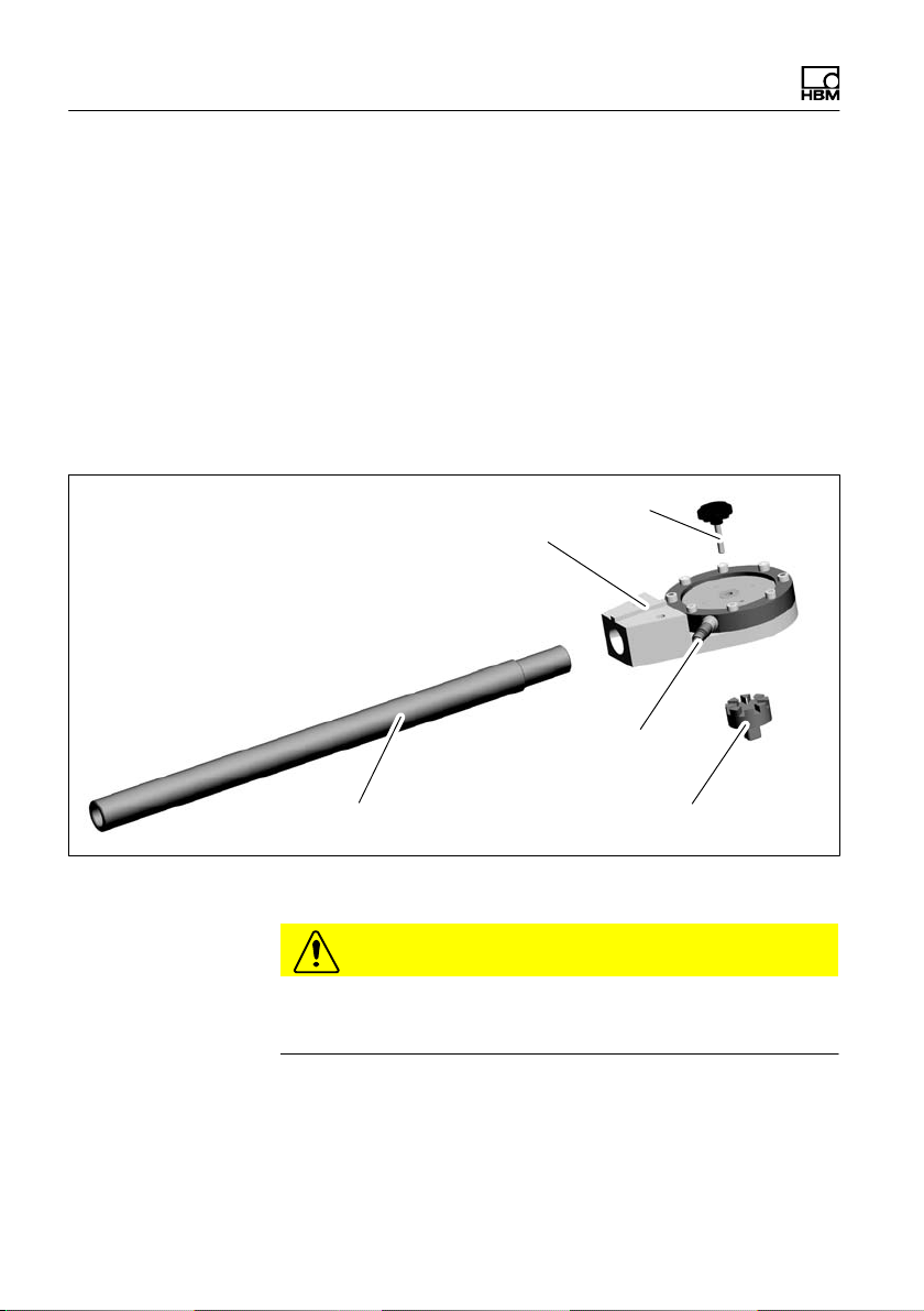
4.1 Mechanical construction
The transfer torque wrench comprises a measuring head
and a lever. A measuring body and an interchangeable
square adapter are integrated in the measuring head.
The supplied connecting cable is connected with the
transducer via a six‐pin Lemo®socket.
Measuring head
Lever
Lemo®socket
Knurled screw
Square adapter
Fig. 4.1 Mechanical construction
CAUTION
The hexagon‐socket screws on the measuring head are
marked with a locking varnish and must not be loosened!

Structure and mode of operation
TTS A1571-3.0 HBM: public 9
4.2 Installation position
The transfer torque wrench can be mounted in any
position. With a clockwise torque, a positive output signal
is produced in conjunction with HBM measuring
amplifiers.
4.3 Conditions at the usage site
The transfer torque wrench is protected to IP22
according to EN 60529.
Transducers must be protected against coarse dirt parti
cles, dust, oil, solvents and humidity.
During operation, the prevailing safety regulations for the
security of personnel must be observed.

Assembling the torque wrench
10 A1571-3.0 HBM: public TTS
5 Assembling the torque wrench
The transfer torque wrench is taken apart and delivered
in a carrying case. The measuring head, the square
adapter, the knurled screw, the lever and the connecting
cable are all separate. Depending on the nominal (rated)
torque, there are one, two or three parts to the lever.
CAUTION
If you want to use a different square adapter from the
accessories program, instead of the one supplied, you
must keep to its maximum permissible torque (see Sec
tion 9, Page 21).
5.1 Fitting the square adapter on the
measuring head
Notice
We recommend that the square adapter is always
installed in the same angular position. The later transfer
torque wrenches have arrows on the measuring head
and on the square adapter for ease of positioning (see
Fig. 5.1). The points of the arrows should point to one
another.
Assembling the torque wrench
TTS A1571-3.0 HBM: public 11
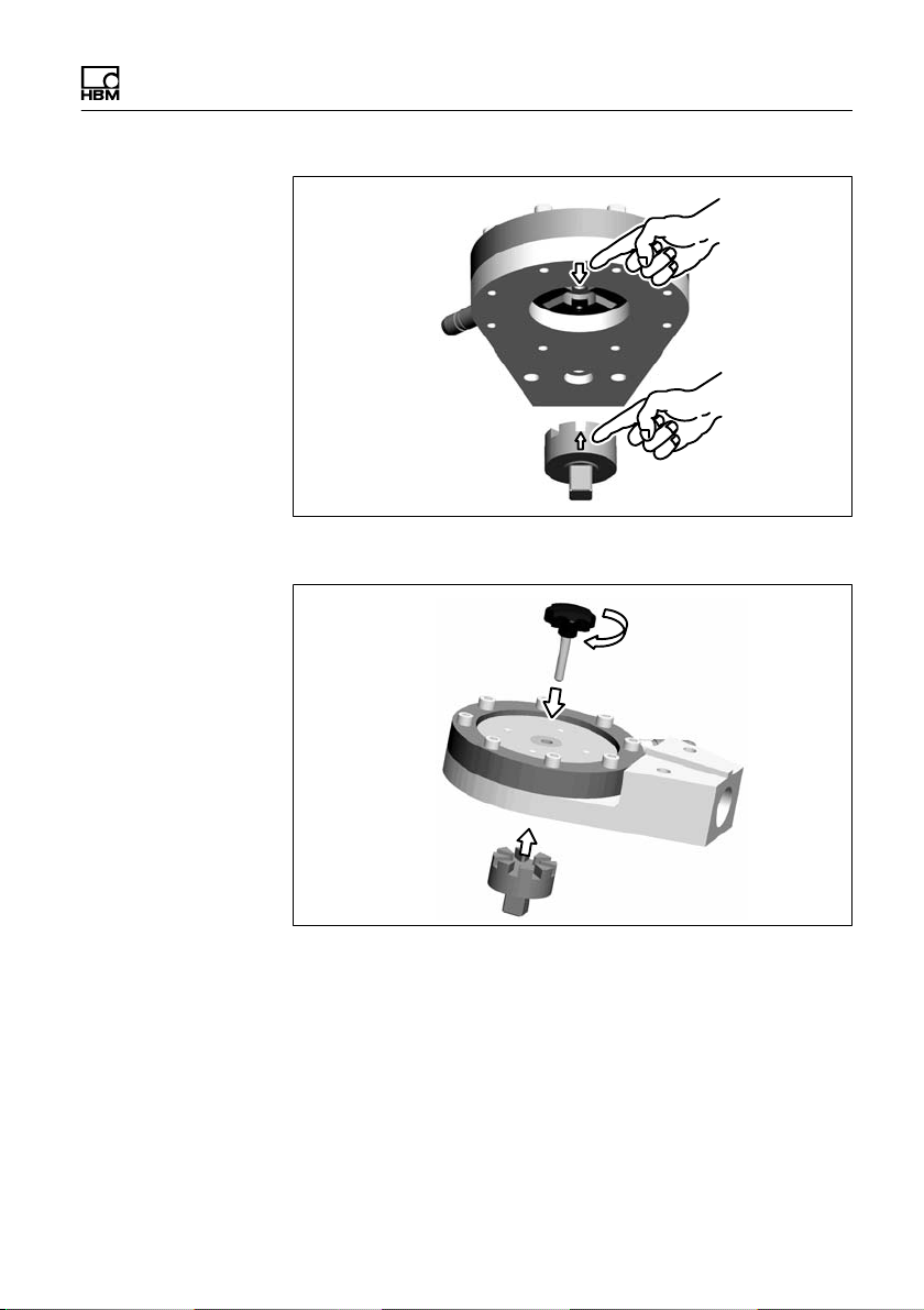
Fig. 5.1 Positional markings
Knurled screw
Measuring
head
Square adapter
Fig. 5.2 Fitting the square adapter on the measuring head
Position the square adapter in accordance with the arrow
markings (see Fig. 5.1) on the measuring head; insert the
knurled screw into the central hole in the measuring head
and screw the square adapter in tight.

Assembling the torque wrench
12 A1571-3.0 HBM: public TTS
Information
By keeping to the same angular position, any symmetry
deviation will not affect the reproducibility of the mea
surement results.
5.2 Fitting the lever
Depending on the nominal (rated) torque, there are one,
two or three parts to the lever. To make assembly easier,
apply a little oil to the mating surfaces of the individual
components.
5.2.1 One‐piece lever (nominal (rated) torque
100 N@m)
SPress down the spring bolts of the lever.
SPush the lever as far as it will go into the receiving
hole in the measuring head.
STurn the lever from side to side until you hear the
spring bolts engage.
Spring bolt
Measuring head
Fig. 5.3 One‐piece lever

Assembling the torque wrench
TTS A1571-3.0 HBM: public 13
5.2.2 Two‐piece lever (nominal (rated) torque
200 N@m)
SFirst join the parts of the lever together by pushing the
longer piece into the shorter one.
SFit the lever and the measuring head, as described in
sub‐section 5.2.1.
Spring bolt
Spring bolt
Fig. 5.4 Two‐piece lever

Assembling the torque wrench
14 A1571-3.0 HBM: public TTS
5.2.3 Three‐piece lever (nominal (rated) torque
500 N@m, 1 kN@m)
SFirst attach the connection bolt of the lever with the
two supplied hexagon‐socket screws (a./f. 5) in the
measuring head.
SPush the center piece over the connection bolt and
tighten the knurled screw.
SNow push the end piece into the center piece and turn
the knurled screw tight.
Connection bolt
Center piece
End piece
Fig. 5.5 Three‐piece lever (500 N@m, 1 kN@m)
5.2.4 Three‐piece lever (nominal (rated) torque
3 kN@m)
SFirst attach the connection bolt of the lever with two of
the supplied hexagon‐socket screws (a./f. 5) in the
measuring head. Make sure you get the right end, as
shown in Fig. 5.7.
SPush the center piece over the connection bolt and
tighten the fastening screws.

Assembling the torque wrench
TTS A1571-3.0 HBM: public 15
SNow push the end piece into the center piece and turn
the fastening screws tight.
Center piece
End piece
Connection
bolt
Fig. 5.6 Three‐piece lever (3 kN@m)
Measuring
head end
20 mm
Lever end
70 mm
Fig. 5.7 Detailed view of end orientation on the connection
bolt

Electrical connection
16 A1571-3.0 HBM: public TTS
6 Electrical connection
6.1 General instructions
Electric and magnetic fields often cause interference
voltages in the measuring circuit. This interference
comes primarily from power lines lying parallel to the
measuring leads, but it can also come from nearby
contactors or electric motors. Interference voltage can
also be coupled galvanically, especially by grounding the
measurement chain at a number of points.
Please follow the below instructions:
SUse only shielded and low‐capacitance measurement
cables for six wire circuit from HBM.
SDo not position the measurement cables parallel to
power lines or control circuits. If this is not possible
(e.g. in cable shafts), protect the measurement cable
with armoured steel tubing, for example and keep it a
minimum distance of 50cm away from the other
cables. Power lines or control circuits should be
twisted together (15 twists per meter).
SGuard against stray fields from transformers, motors
and contactors.
SDo not ground the transducer, the amplifier and the
indicator more than once. All the measurement chain
devices must be connected to the same grounded
conductor.
Grounding concept (Greenline)
The cable shield of the connection cable is connected to
the measuring head of the transducer. This encloses the
measurement system in a Faraday cage. Any electro

Electrical connection
TTS A1571-3.0 HBM: public 17
magnetic interference active here does not affect the
measurement signal.
In the event of interference due to potential differences
(equalization currents) the zero operating voltage and the
housing ground should be isolated from one another at
the amplifier and a potential equalization line should be
run between the housing and the amplifier housing
(flexible stranded wire, 10 mm2conductor cross‐section).
6.2 Connector pin assignment
The transfer torque wrench comes supplied with a
ready‐made 6‐wire connection cable (six‐wire circuit).
The pin assignment for the HBM amplifier can be found
in the following table:
Top view
1
8
9
15
Pin Wire color Connection
1 yellow Shielding connected to enclosure
ground
5 black Excitation voltage (-UB)
6 blue Excitation voltage (+UB)
8 white Measurement signal (+UA)
12 gray Sensor circuit (-)
13 green Sensor circuit (+)
15 red Measurement signal (-UA)
Extension cables should be of the shielded, low‐capaci
tance type. HBM provides the 1‐KAB254‐10 cable
(ready‐made) and the KAB8/00‐2/2/2 cable (by the
meter, can also be supplied with fitted connecting plug)
specifically for this purpose.

Maintenance
18 A1571-3.0 HBM: public TTS
7 Maintenance
The transfer torque wrench is maintenance free.
Other manuals for TTS
2
Table of contents
Languages:
Other HBM Power Tools manuals

Popular Power Tools manuals by other brands


Pro's Kit
Pro's Kit Pro'sKt SS-621 Series user manual

FLORABEST
FLORABEST FBK 4 C2 instructions

master mechanic
master mechanic 181683 owner's manual

SPX FLOW
SPX FLOW Power Team PTPH-100T operating instructions

Far Tools
Far Tools DPB 16E Original manual translation

Far Tools
Far Tools PM 550T Original manual translation