HD Rehab HD motion Series User manual
User Manual | English

© 2020 HD Rehab AB
This user manual is available in PDF format at hdrehab.com.

3
HD Motion | User Manual
CONTENTS
1. Warranty 4
2. General information 5
2.1 Intended use 5
2.2 General safety aspects 5
2.3 Tests 6
2.4 Wheelchair identication 7
2.5 Wheelchair parts 7
2.6 Delivery inspection 7
2.7 Symbols and markings 7
3. Functions and settings 8
3.1 Included spanner 8
3.2 Brakes 8
3.3 Wheels 9
3.4 Tip protectors 9
3.5 Push bar 10
3.6 Cushions and covers 10
3.7 Seat tilt and Back recline 11
3.8 Backrest height 12
3.9 Setting the Flexi-back 12
3.10 Adjustable seat width 12
3.11 Adjustable seat depth 13
3.12 Positioning of leg rests 13
3.13 Armrests 13
3.14 Leg rests 14
4. Accessories 16
4.1 Headrest 16
4.2 Thoracic support 17
4.3 Tray table 17
4.4 Knee spacer & Leg spacer 18
4.5 Mounts for belts and
harnesses 18
5. Transport 19
5.1 Vehicle transport with user
seated in wheelchair 19
5.2 Weight of removable
components 19
5.3 Folding the wheelchair for
transportation 20
5.4 Transferring in and out of
the wheelchair 20
5.5 Driving technique 21
6. Maintenance and care 22
6.1 Daily functional checks 22
6.2 Long term storage 23
6.3 Recycling and disposal 23
7. Technical data - Measurements 23

4
HD Motion | User Manual
THANK YOU FOR CHOOSING A WHEELCHAIR FROM HD REHAB,
WE HOPE IT WILL SERVE YOU WELL
WE MANUFACTURE QUALITY OF LIFE
HD Rehab helps people achieve an improved quality of life. Our products help make
the lives of users, their families, and caregivers easier, safer, and more comfortable.
HD Rehab oers assistive products for people living with disability. Our primary product is wheelchairs,
which we have been designing, developing, and manufacturing for over 40 years. We accept no
compromises in quality. Precision, safety for user and caregiver, function, and design are our guiding
principles. We are condent that you will feel the dierence compared to any other wheelchair.
GLAD TO BE FLEXIBLE
Whether you are a user, a family member, or a caregiver we welcome your requests and opinions. Our
designers and developers work closely with the production team at our facility on the island of Lidingö
in Stockholm. Our creative employees use their specialist knowledge, experience, and inventiveness to
nd solutions for the unique needs of each individual.
1. WARRANTY
The warranty is only valid if the product is used as directed and the service and cleaning instructions
are followed.
THE WARRANTY COVERS:
Frame 5 years against defects in materials, manufacturing and/or assembly.
Leg-/arm-/headrests Two years against defects in materials, manufacturing and/or assembly.
Upholstery Two years against defects in materials and faults in manufacture.
Gas springs Two years against defects in materials and faults in manufacture.
WARRANTY & LIMITATION OF LIABILITY
HD Rehab assumes no liability for damages arising out of the following:
- That the instructions in the manual were not followed.
- Incorrect installation or setup by a third party other than HD Rehab.
- Unauthorized modications or adaptations.
- Use of spare parts from other manufacturers than HD Rehab
- Use by persons weighing more than the maximum user weight stated on the wheelchair.
- That the wheelchair is adjusted to an inappropriate position or setting for the user.

5
HD Motion | User Manual
2. GENERAL INFORMATION
HD Motion is a class 1 CE labelled medical device.
2.1 Intended use
The HD Motion wheelchair is a manual wheelchair designed for youth who can propel themselves to
a certain extent. It can also be used if the user does not propel themself. HD Motion can also in some
cases be used by small adults. See Prescriber information (doc.nr. 96715-1) for more information.
HD Motion is intended for users in need of much comfort and support when seated. The seat and back
on both models can be tilted in various positions to give the user a varied position during activity and
rest. A varied seat position is very important. Note that prolonged sitting without a position change
can lead to discomfort and harmful pressure.
Prescription by a medical professional is required before beginning to use a HD Motion. This applies
to new wheelchairs as well as when a used chair changes users. Note that a new prescription may
be needed if a user’s disability or body size changes, or if new needs arise. Check this regularly. All
prescription, adjustment, and monitoring of the wheelchair must be carried out by qualied personnel.
Where the wheelchair has several users, each patient’s specic needs must be taken into account. If the
wheelchair is to change users the covers of the back and seat cushions must be washed or replaced.
Washing instructions are found on the cushion covers.
HD Motion in standard conguration is built to withstand the challenges and strains that arise in
everyday situations and environments. In cases where extra durability is required the wheelchair can
be made in a reinforced version. When using a drive motor, when frames are reinforced, and/or with
other special adaptations, and with hard use the lifetime is limited to 5 years. Care and maintenance
should be done more frequently in these cases.
The wheelchair is approved for use as a seat during transportation in vehicles.
2.2. General safety aspects
HD Motion is intended for use both indoors and outdoors. Before using the wheelchair, it is important
that users and carers are familiar with how the chair works and should be used.
Test the driving characteristics and features.
• Read the whole manual and have it available. Note that deviations may occur especially if
the wheelchair is specially equipped or adapted. The wheelchair can also be equipped with
accessories and equipment from other suppliers.
• From a safety perspective, it is important that the maintenance instructions (see Section 6) are
followed. A good rule is to keep the wheelchair clean and periodically test the controls and brakes.
• Be careful with all cables so that they do not get damaged. Particularly, when the chair has been
transported it is good to do a further check to note that no cables have been damaged.
• If damage is detected or any component found to be missing the wheelchair must be taken out of
service until this is xed.
• The wheelchair should be operated and used judiciously to avoid unnecessary risks.
• The wheelchair should not be operated by other children.
• If the wheelchair is exposed to external heat sources such as sunlight, some parts may become
hot. Pay attention to this so that no user is harmed.
• Be aware that certain items of clothing are not suitable as they may get caught in the wheels. Be
especially careful with scarves and similar items that can tighten around the user’s neck if caught.
• Sitting for long periods entails certain risks, e.g. circulation disorders such as thrombosis (blood
clots). This applies primarily to adult users. If such a problem is suspected, gather information
regarding symptoms and contact medical care. A varied seating position is important.
CUSHIONS
• Seat cushions made of foam have a limited lifetime depending on use. Cushions should be checked
regularly and replaced as needed for the safety and comfort of the user. This helps avoid harm such
as pressure sores. If harm is suspected, gather information regarding symptoms and contact medical
care. See also Section 6. Maintenance and care.

6
HD Motion | User Manual
POSITIONING AIDS
• All use of positioning aids such as positioning belts or chest harnesses must be assessed by the
care provider according to healthcare regulations.
• There is a risk of the user sliding forward in the wheelchair and becoming caught in a chest harness.
A harness must always be used in combination with a positioning belt. See also Section 4.5.
• Always read the user manual from the manufacturer of the positioning aid.
RISK OF TIPPING
• Do not hang bags, oxygen bottles, or other items on the seat back.
• Some users have involuntary movements, or are very active, and want to grab hold of solid
objects (e.g. door frames). Use caution with these users and ensure that you are aware when their
behaviour can tip the wheelchair. Avoid parking near xed objects.
RISK OF PINCHING
• As the wheelchair has many dierent conguration options the caregiver must be alert to the user’s
position in the chair, to avoid the possibility that the user could be pinched. The risk of pinching is
small under normal circumstances.
• Keep in mind that the user cannot always communicate that a pinching injury is occurring.
LIFTING
This advice is general since there are many dierent lifting aids available.
• When lifting in and out of the wheelchair be very attentive that the user’s arms and legs do not get
caught. Fold in the footrests or remove them so that they do not get in the way. Follow the lifting aid
instructions carefully.
• Training is often required to operate the lifting aid.
CE MARKED ACCESSORIES, CUSTOMIZING
• HD Rehab has a number of CE-marked accessories that are authorized for use with the wheelchair
while maintaining the CE marking. There are also combination agreements covering accessories
from other manufacturers that are approved for use with HD Motion while maintaining the CE
marking. Accessories that have not been approved may not be used.
• Any change to the wheelchair or use of accessories that are not certied and CE-marked by HD
Rehab is a special adaptation and a transfer of liability occurs. Specially adapated wheelchairs do not
retain CE marking and the warranty is void. Always consult HD Rehab if unsure about what applies.
Help is available for special adaptations for individual users.
DAILY FUNCTIONAL CHECK
To ensure that the wheelchair works as it should, a daily function test should be performed before the
user is positioned in the seat. See section 6.1 Daily functional check.
REPLACEMENT PARTS AND SERVICE
If the wheelchair is in need of replacement parts or service contact the reseller.
SAFETY NOTICES AND PRODUCT RECALLS
Information regarding any safety notices and product recalls can be found at hdrehab.com.
WARNINGS
In addition to these general safety aspects there are warnings and notices contained in each section in
the manual. They are marked with a warning triangle as follows:
- Here is the warning.
2.3 Tests
Wheelchair tests and crash test have been carried out for HD Motion at RISE Research Institutes
of Sweden, Borås, Sweden (ISO 7176-19:2008 and EN 12183:2014, and ISO 7176-19 respectively).
Resistance to ignition tests have been carried out at Swerea IVF, Mölndal, Sweden (ISO 7176-16:2013,
EN 1021-1, and EN 1021-2). More information and certicates are found at hdrehab.com.
7
HD Motion | User Manual
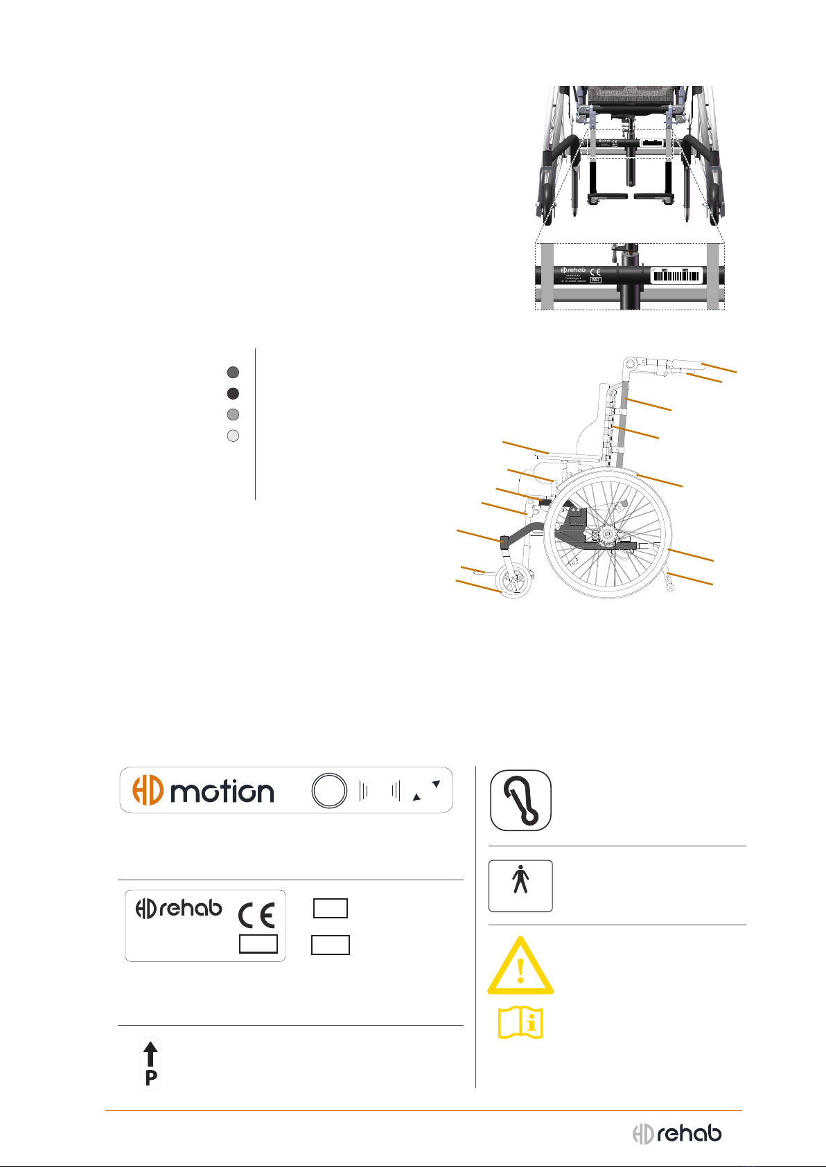
2.4 Wheelchair identication
Manufacturer, production year, serial number (SN), and article
number (REF) in text and in bar code format are printed on
the front cross tube of the wheel frame, see Figure 1.
2.5 Wheelchair parts
1 Wheel frame 8 User brake
2 Seat frame 9 Push bar
3 Back frame 10 Tip protector
4 Back system 11 Leg rest
5 Drive wheel 12 Foot rest
6 Castor 13 Armest, side support
7 Caregiver brake 14 Fender
2.6 Delivery inspection
ALWAYS DO THE FOLLOWING ON DELIVERY:
- Check that the wheelchair does not have any
visible damage.
- Report any shipping damage to the transport
company immediately.
Follow the unpacking instructions that come with the delivery. This may be supplemented with further
instructions depending on the how the wheelchair is equipped.
2.7 Symbols and markings
The following markings are on the wheelchair. For more detail see document Labeling, doc.nr. 96764-1.
Model label. Shows that the model is HD Motion, as
well as the wheel size, the seat width, and frame length of
the wheelchair.
CE-marking. Shows that the wheelchair is a CE marked
medical device and who the manufacturer is. SN stands for
Serial Number and REF for Reference (article) number.
Transport attachment.
Marks the anchor points for
transport.
Max user weight. Shows the
maximum user weight for the
wheelchair.
Attention required.
Wheelchairs with alternate
conguarations or are
equipped with accessories that
carry increased or dierent risks
are marked with this symbol.
Parking brake. Shows how the sleeve
on the brake lever is moved to activate the
parking brake.
Figure 2. The parts of the wheelchair
Figure 1. Labels for wheelchair identication
9
7
3
4
13
1
12
6
11
2
8
10
14
5
L
3422
HD Rehab AB
Tryelslingan 4
181 57 LIDINGÖ, SWEDEN MD
SN
REF
00105
(01)07322583581063(21)00105
35810-619
HD Rehab AB
Tryelslingan 4
181 57 LIDINGÖ, SWEDEN
MD
00105
(01)07322583581063(21)00105
35810-619
HDRehab AB
Tryelslingan4
18157 LIDINGÖ, SWEDEN
MD
Max: 75 kg
8
HD Motion | User Manual
3. FUNCTIONS AND SETTINGS
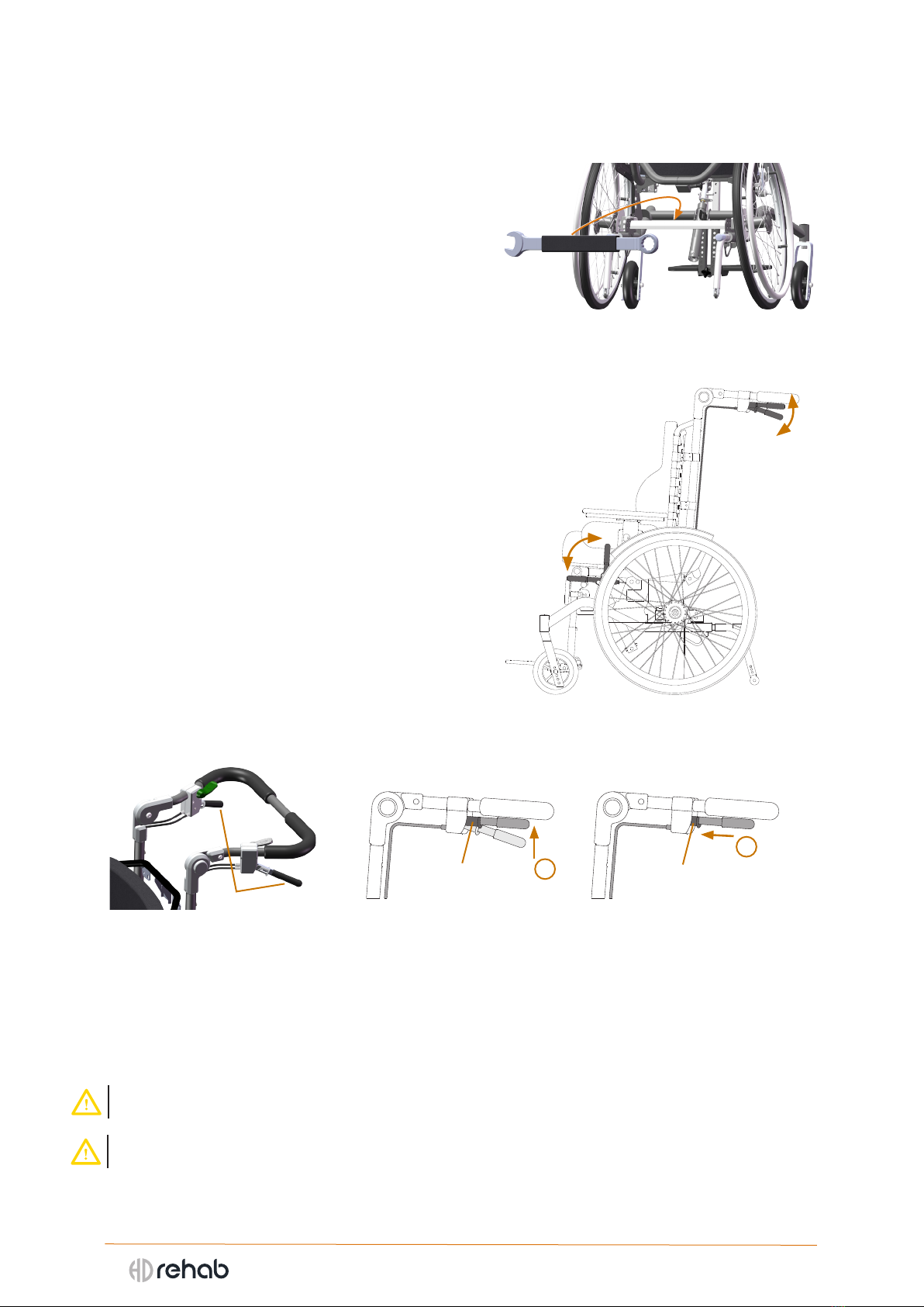
3.1 Included spanner
Most adjustments for HD Motion are done without
using tools. In those cases where a tool is required,
it is a most often a 10 mm spanner. This spanner is
included with the wheelchair, placed on the rear
crossbar (Figure 3).
3.2 Brakes
HD Motion is equipped with combined service- and
parking- disc brakes that can be activated by both the
caregiver (1 in Figure 4) and the user (2 in Figure 4).
CAREGIVER BRAKES
The caregiver brake handles are are located under the
push bar (1 in Figure 5). The brakes are activated by
pushing the handles up towards the push bar. Holding
the brake handles slightly pressed achieves a braking
eect, for example when moving downhill.
The parking brake is activated by pressing the brake
handles up towards the push bar and then moving the
locking sleeve (ain Figure 6) forward so that the brake
handle is locked in place, see Figure 6.
NOTE: Make sure the locking sleeve is pushed forward
suciently so that it sits securely.
NOTE: Always use both left-hand and right-hand
parking brakes together.
USER BRAKES
The user can engage the brakes by moving the brake levers forward from the wheels. The brakes are
released by moving the brake levers back towards the wheels.
Adjustment of the wheel lock must be performed by qualied personnel; instructions are in the
technical manual.
- Parking brakes are not suitable for use when the wheelchair is on a surface that slopes more than 7°.
- Adjustment of the disc brakes should only be done by a qualied technician.
Figure 4. Caregiver brakes and user brakes
Figure 5. Brake handles Figure 6. Parking brakes
Figure 3. Included spanner
1
2
1
aa
2
1

9
HD Motion | User Manual
3.3 Wheels
HD Motion is equipped with 20”, 20”, or 24” drive wheels
depending on model and conguration. The drive wheels have
quick-release connectors. Several tire alternatives are available
when ordering. The castors are 175mm as standard but other
options are available.
REMOVING THE WHEEL:
- Press the quick-release button (1), see Figure 7.
- Remove the wheel.
MOUNTING THE WHEEL:
- Insert the axle (2) in the wheel mount housing (3), see Figure 7.
- Press the quick-release button (1) on wheel hub.
- Press the wheel so that the three pins on the hub t in to the
three holes in the brake disc.
- Release the quick-release button and check that the wheel is
secured by pulling on it.
- Make sure the quick-release button has slid out and that the
wheel is xed.
- Be careful not to allow the user’s hands to go in to the wheels.
- Be aware that certain items of clothing are not suitable as
they may get caught in the wheels. Be especially careful with
scarves and similar items that can tighten around the user’s
neck if caught.
- If the wheelchair is equipped with pneumatic tires the
recommend air pressue is indicated on the tires. Normally the
air pressure is 300 kPa.
3.4 Tip protectors
Tip protectors are standard equipment on HD Motion and
should always be used. The tip protectors can be set in three
positions by means of a snap lock, see Figure 8. The snap lock
is released by pushing it in (1, Figure 8). It is also possible
to temporarily turn up the tip protectors if necessary when
pushing the wheelchair, see Figure 9.
TURNING UP THE TIP PROTECTORS:
- Using hand or foot, push in on the plug of the tip protector
(1 in Figure 9).
- The tip protector is thus released and turns inward (2).
- Turn up the tip protector to the rest position.
The tip protector is reutrned to the active position by turning
it down with hand or foot.
- Always ensure that the tip protectors are turned all the way
down and are in the locked position.
Figure 7. Wheel removal
Figure 9. Turning up tip protector
Figure 8. Tip protector with 3
positions set by snap lock
3 positions
1
123
3
2
1
10
HD Motion | User Manual
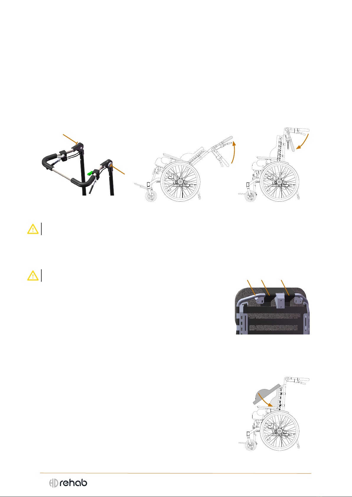
3.5 Push bar
HD Motion is equipped with an adjustable push bar with a large range upwards and downwards.
Adjusting upwards allows the caregiver to set it to a comfortable position. It can even be set to a
suitable position if the wheelchair is driven in a reclined position (see Figure 11). Adjusting the push
bar all the way down allows the caregiver to come close to the user from behind in a care situation (see
Figure 12).
HEIGHT ADJUSTMENT OF THE PUSH BAR:
- Push the buttons (Figure 10) on both left and right side and move the push bar to the desired postion.
- Release the buttons and check that the push bar has clicked in to a locked position.
- Check that brake and control cables run freely and are undamaged. The cables should run along the
tubes of the back frame.
- The caregiver must never push the wheelchair in an uncomfortable position. Hands must be able to
easily grasp the push bar and operate the brakes and tilt/recline controls.
3.6 Cushions and covers
Seat and back cushions are attached with velcro and are easily removable and interchangeable.
- Check cushions according to the maintenance directions. Worn out
cushions can cause pressure ulcers.
POSITIONING THE SEAT CUSHION
- Align the cushion over the seat plate and place it straight down. The
back of the cushion is labelled. The underside is black and smooth.
- Check that the cushion is secure.
REMOVING THE SEAT CUSHION:
- Grasp the front edge of the cushion and pull straight up.
POSITIONING THE BACK CUSHION:
- Attach the straps (1 in Figure 13) at the top of the cushion around the Flexi
back’s tubes (2) with velcro as shown (If a solid back is used the velcro
attaches to the back of it). Securing the cushion vertically reduces the risk
of the cushion sliding down when moving in to and out of the wheelchair.
- Push the cushion forward and press rmly against the back (Figure 14).
- Check that the cushion is placed correctly and sits securely.
REMOVAL OF BACK CUSHION:
- Take hold of the lower edge of the cushion and pull up.
- Loose the straps at the top.
REMOVABLE COVER
Both the seat and back cushion covers are tted with a zipper for easy
removal and replacement. Washing instructions are on the label.
Figure 10. Push bar release buttons Figure 12. Push bar downFigure 11. Push bar up
Figure 13. Straps fastened
around Flexi frame
Figure 14. Setting cushion
12 1

11
HD Motion | User Manual
3.7 Seat tilt and Back recline
Figure 16 shows the wheelchair in back reclined and seat tilted positions.
- The controls should be handled with moderate force and should
always be used one at a time, never both at the same time.
- Never hang items on the levers.
SEAT TILT
The seat tilt is controlled by the green lever on the right side of
the push bar, 1in Figure 15. As standard, the seat can be tilted
continuously between 0° and 30°.
A gas cylinder provides supporting force when tilting backward. Note that the seat will feel heavy to
tilt forward if no one is sitting in the wheelchair.
OPERATING THE SEAT TILT:
- Grip the push bar with both hands.
-
Release the lock by pressing the green lever down gently, hold it down.
- Push on the push bar to set the desired seat tilt, release the green lever.
BACK RECLINE
The back recline angle is controlled by the gray lever on the left side of the push bar, 2in Figure 15. As
standard the back can be reclined continuously between 90° and 120°.
A gas cylinder provides supporting force when tilting forward. Note that this means the back will feel
heavy to recline backward if no one is sitting in the wheelchair.
OPERATING THE BACK RECLINE:
- Grip the push bar with both hands.
- Release the lock by pressing the gray lever down gently, hold it down.
- Push on the push bar to set the desired back recline angle, release the gray lever.
- Risks exist for some accessories when adjusting recline angle. For example pinching towards the table
when raising the back. Similar risks also appear for belt, pommel and hemiplegic armrest.
Figure 15. Controls for seat
tilt (1) and back recline (2)
Figure 16. Three positions: Max back recline, max seat tilt, and both recline and seat in max position
2
1

12
HD Motion | User Manual
3.8 Backrest Height
The backrest height can be adjusted approximately 6 cm in the tracks
where the back support is secured. This requires a 10mm spanner. The
procedure is the type of back support (Flexi-back or Solid back).
HEIGHT ADJUSTMENT OF THE BACKREST:
- Loosen the two nuts on each side a few turns (1 in Figure 17).
- Push the backrest up or down to the desired height.
- Tighten the nuts securely.
- Check carefully that all cables are whole and in place.
3.9 Setting the Flexi-back
Guide for setting the Flexi-back:
1. Before the user sits in a wheelchair;
a. Loosen the straps thoroughly.
b. Make sure the back cushion is properly positioned in the seat.
See instructions in 3.6 Cushions and covers.
c. Loosen the nuts for height adjustment of the Flexi-back.
2. Positioning the user;
a. When lifting the user into the chair, tilt the seat unit backward.
In many cases it can be helpful to recline the backrest slightly.
b. Position the user fully in to the wheelchair, between the side
tubes of the frame. This is required in order to form the Flexi-
back properly to the user’s back
3. With the user sitting in the wheelchair;
a. Set the backrest at the desired height.
b. Adjust the velcro straps to support the user’s back.
c. Tighten the nuts for the seat back height adjustment.
3.10 Adjustable seat width
HD Motion is width-adjustable in 3 positions. Seat width is determined
by the position of the armrest brackets, see Figure 18. Table 1 show the
nominal seat width for each model.
Table 1 - Nominal seat width in each position [cm]
Model Inner position Middle position Outer position
HD Motion sw30 28 30 32
HD Motion sw34 32 34 36
SETTING THE SEAT WIDTH:
- Remove the seat cushion and armrests.
- Unscrew the two screws that secure the armrest bracket (Figure 18).
- Move the armrest bracket to the desired position. NOTE: The bracket
is not symmetric inside, the at side faces inward.
- Set the washers in place and tighten the screws.
- Repeat the same steps with the other armrest bracket. NOTE: Right-
hand and left-hand armrest must always be in the same position.
- Check carefully that all screws are securely tightened.
- If the wheelchair is equipped with a belt mount it takes the place of
the washers.
Seat width can in some cases be adjusted with the user sitting in the
wheelchair, but extra attention is required.
- Adjsutment of wheelchair seat width is to be done only by
qualied personnel.
Figure 17. Nuts for height
adjustment
Inner position
Middle position
Outer position
Figure 18. Left-hand
armrest bracket
1
13
HD Motion | User Manual
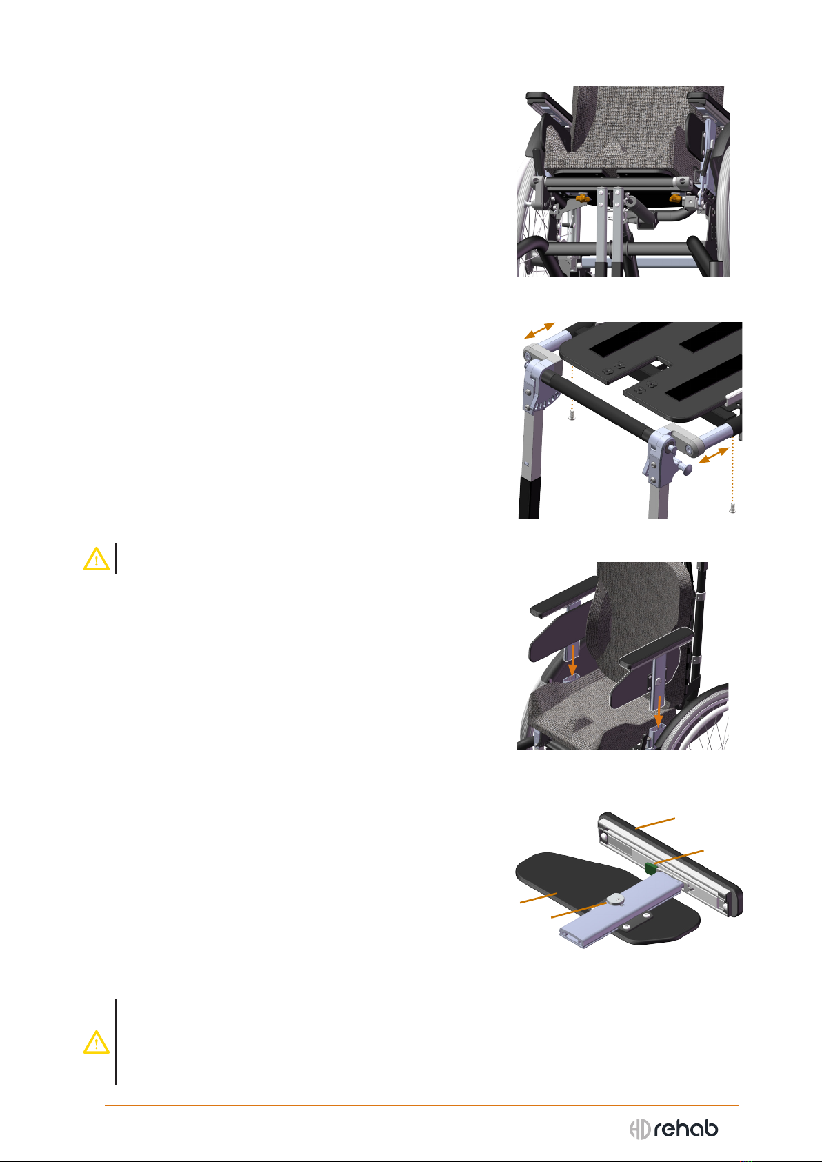
3.11 Adjustable seat depth
The depth of the seat plate can be continuously adjusted in a
6,5 cm range. It is secured by two knobs under the seat.
SETTING SEAT DEPTH:
- Loosen the two knobs a few turns (Figure 19).
- Slide the seat plate to the desired position.
- Firmly tighten the two knobs.
- Check that the seat plate is securely locked.
The seat plate can be pulled out, for maintenance reasons,
by removing the knobs completely.
3.12 Positioning of leg rests
The leg rest unit can be adjusted 6 cm in ve positions.
POSTIONING THE LEG RESTS:
- Remove the two bolts (Figure 20) that secure the leg rest
unit to the seat frame. The same procedure applies to both
Separate leg rests and Centre leg rest.
- Pull out or push in the telescoping rods on each side to
move to the desired position.
- Check from underneath to see that the holes in the
telescoping rods line up with the holes in the seat frame
- Tighten the screws in place
- When adjusting the leg rest unit position check that the
seat plate is in a suitable position and adjust if necessary
3.13 Armrests
Armrests are placed in mounts on each side of the seat
(Figure 21). They can be adjusted in height and depth.
Components, see Figure 22:
1 Armrest pad
2 Side support
3 Locking button
4 Locking lever
HEIGHT ADJUSTMENT:
- Push the button (3 in Figure 22) and hold it in.
- Set the desired height. The post is marked with 1 cm intervals.
- Release the button and pull lightly on the the armrest pad so
the lock snaps in place.
DEPTH SETTING:
The armrest pad can be adjusted to nine depth settings.
- Press the locking lever (4 in Figure 22) and set the desired
position.
- Release the locking lever.
- Make sure the armrest pad is locked in position by pulling
lightly on it.
- If the armrest pad is adjusted backward when the back is reclined it is possible for the back to be blocked
by the armrest and unable to be tilted up. Check and move the armrest pad forward when necessary.
- With the seat width at the widest setting and the armrest pads adjusted backward it is possible for them
to rub against the fenders when the seat is tilted backward. The wheelchair must never be driven in this
conguration.
Figure 21. Armrests are inserted into
the brackets on each side of the frame
Figure 22. Armrest components
Figure 19. Seat plate knobs
Figure 20. Bolts for leg rest unit
2
3
1
4
14
HD Motion | User Manual
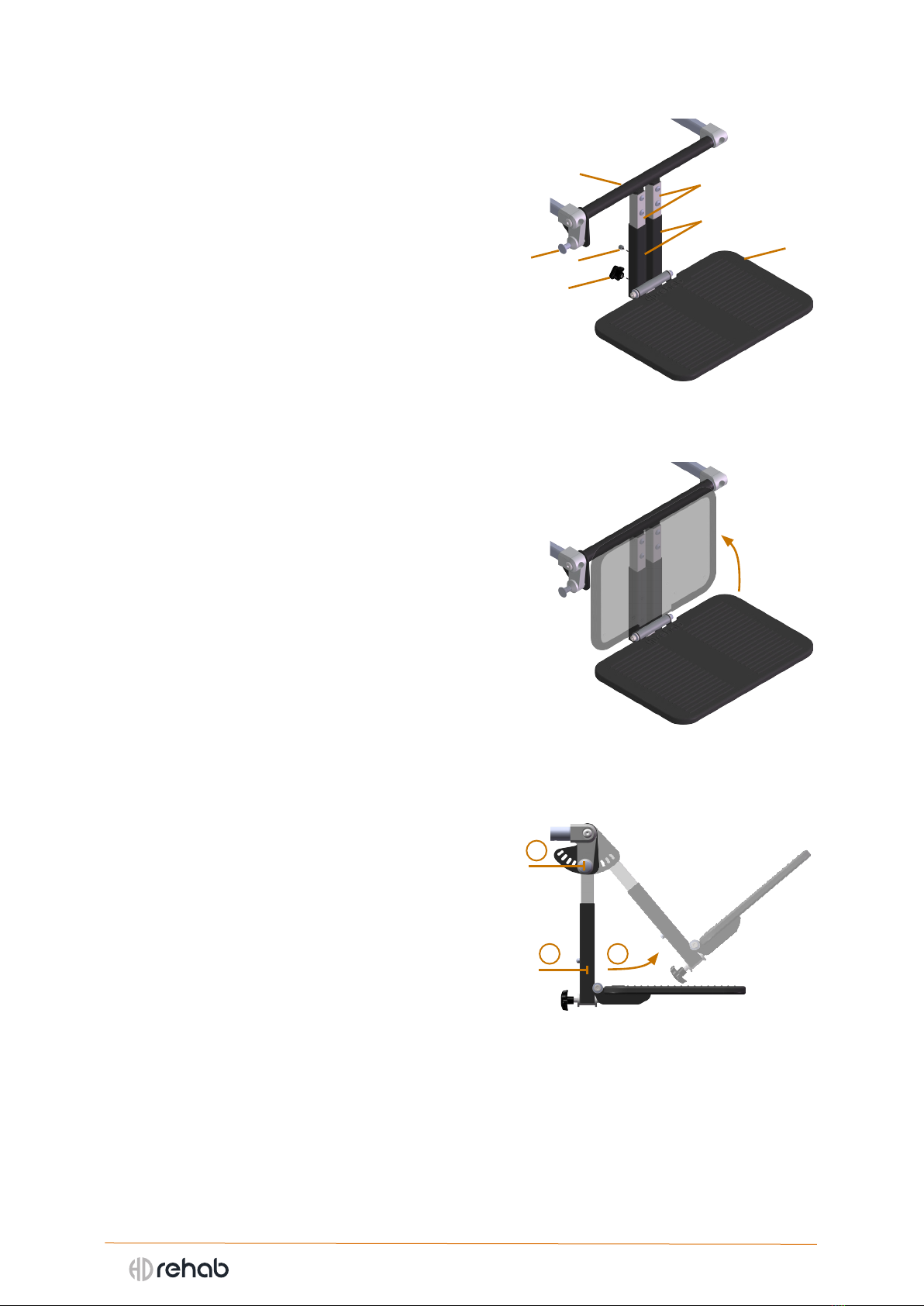
3.14 Leg rests
CENTRE LEG REST
Centre leg rest can be angled between 80° and 140° in
7 positions. The one-piece footrest can be adjusted in
height and angle. The footrest can also be folded up
against the leg rest tubes to make it easier to get in-to
and out-of the wheelchair (see Figure 24).
Components, see Figure 23:
1 Locking knob, leg rest angle
2 Central tube
3 Leg rest tubes
4 Footrest tubes
5 Footrest plate
6 Snap lock, footrest
7 Knob, footrest angle
HEIGHT ADJUSTMENT OF ONEPIECE FOOTREST:
- Push in the snap lock (6 in Figure 23) and move the
footrest tubes to the desired position.
ANGLE ADJUSTMENT OF ONEPIECE FOOTREST:
- Turn the knob (7 in Figure 23) until the footrest reaches
the desired position.
ANGLE ADJUSTMENT OF CENTRE LEG REST:
- Grip the footrest tubes near the bottom (1 in Figure 25).
- Pull the knob (2) on the right hand side and move the
leg rest to the desired position (3).
- Release the knob and push the leg rest lightly in either
direction so that the locking pin snaps in place.
Figure 23. Centre leg rest components
Figure 24. Folding up footrest
Figure 25. Angle adjustment
16
7
2
4
3
5
3
2
1
15
HD Motion | User Manual
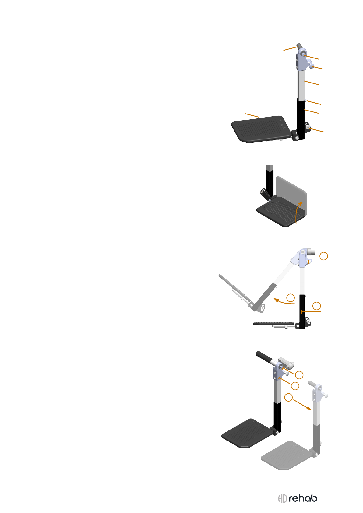
SEPARATE LEG RESTS
Separate leg rests can be angled between 80° and 140° in 7
positions. The footrests can be adjusted in height and angle.
The footrests can also be folded up to the side to make it
easier to get in-to and out-of the wheelchair (see Figure 27).
Components, see Figure 26:
1 Release button for leg rest removal
2 Locking knob, leg rest angle
3 Leg rest pin
4 Leg rest tube
5 Footrest tube
6 Footrest plate
7 Snap lock, footrest
8 Screw, footrest angle
HEIGHT ADJUSTMENT OF SEPARATE FOOTRESTS:
- Push in the snap lock (7 in Figure 26) and move the
footrest tube to the desired position.
ANGLE ADJUSTMENT OF SEPARATE FOOTRESTS:
- Loosen the bolt (8 in Figure 26), 10 mm spanner.
- Move the footrest plate to the desired angle.
- Tighten the bolt securely.
ANGLE ADJUSTMENT OF SEPARATE LEG RESTS:
- Grip the footrest tube near the bottom (1 in Figure 28).
- Pull the knob (2) and move the leg rest to the desired
position (3).
- Release the knob and push the leg rest lightly in either
direction so that the locking pin snaps in place.
REMOVAL OF SEPARATE LEG RESTS:
- Grip around the leg rest joint (1 in Figure 29).
- Push in the release button (2).
- Pull the leg rest away from the leg rest mount (3).
MOUNTING SEPARATE LEG RESTS:
- Align the leg rest pin in the seat frame.
- Push in on the release button and push the leg rest in to
the seat frame.
- Release the button and push the leg rest lightly in either
direction so that the locking pin snaps in place.
Figure 27. Folding up footrest
Figure 28. Angle adjustment
Figure 26. Separate leg rest components
Figure 29. Removal of leg rest
3
2
1
3
1
2
7
65
4
8
2
1
3

16
HD Motion | User Manual
4. ACCESSORIES
The following sections briey describe the accessories that are available for HD Motion. They are all
CE-marked and approved for use with the wheelchair.
More information about each accessory is available on the respective information sheet.
Instructions for installing each accessory is found on the respective accessory assembly instructions.
- Never use accessories that are not approved for HD Motion. The wheelchair is then considered a specially
adapted product. Read more in 2.2. General safety aspects.
4.1 Headrest
The headrest consists of two parts, a cushion and a
mount. The cushion is available in a larger and a smaller
version. The headrest can be equipped with one or two
removable side supports to improve lateral stability.
Components, see Figure 30:
1 Cushion
2 Mounting prole
3 Bracket (attached to backrest)
4 Knob, prole position
5 Link plates
6 Nuts, link plate adjustment
7 Bolts, lateral adjustment
8 Side support
9 Bracket, side support
10 Knob, side support position
11 Nut, side support angle
12 Screw, side support cushion angle in/out
13 Nut, side support cushion angle up/down
The mounting prole is placed though the bracket (3 in Figure 30) and then secured in place by
tightening the knob (4 in Figure 30). The cushion can be adjusted forward and back by loosening the
link plate nuts (6 in Figure 30), then tightening the nuts again after adjusting.
LATERAL ADJUSTMENT:
When needed the headrest can be adjusted laterally to suit the user.
- Loosen the bolts (7 in Figure 30)
- Move the headrest to the desired position, tighten the bolts.
ADJUSTMENT OF SIDE SUPPORTS:
The depth of the side support is set using a knob (10 in Figure 30). The angle of the side support can
be adjusted up and down by loosening the nut (11 in Figure 30) in the side support bracket. Adjusting
the angle of the side support cushion inwards or outwards is done by loosening the screw (12 in Figure
30), and it can be angled up and down by loosening the nut (13 in Figure 30).
- Do not hang things on the headrest, it will increase tipping risk.
- For users with particular/involuntary movements there is a risk of getting caught between the headrest
and the wheelchair. An individual assessments must be done to determine what type of headrest is
suitable for the user.
Figure 30. Headrest components
4
3
2
5
7
6
11
13
12
10
9
8
1

17
HD Motion | User Manual
4.2 Thoracic support
The thoracic support is mounted by inserting the prole (1 in Figure
31) in the thoracic support mount (2) on the backrest. It is secured
at the desired position with a knob (3). Note: Do not tighten too
hard, the knob and mount can be damaged. The thoracic support
is easy to swing out of the way by pushing a button (4), for
example when moving in to or out of the wheelchair.
The cover is removable and mounted with velcro. Washing
instructions are on the label.
SETTINGS
The thoracic support can be adjusted in height, and the cushion
can be formed in angle and depth to create a good t against the
body. See the Thoracic support user manual for details.
- Note that the use of the thoracic support requires careful adjustment to ensure the user receives
good support and that the thoracic support does not cause pressure that can lead to injury.
- Avoid placing the thoracic support near the armpit as the area is generally considered to be
intimate and pressure sensitive.
4.3 Tray table
The tray table is intended as a general resting surface for
smaller items, and in some cases can help to position the
user by providing support for the arms.
Mounting is done by placing the table tray on the front
of the armrests, then pushing it in until it clicks in place
on the mounting pins that are attached below to the
armrest pads. See Figure 32.
To remove the tray table, grasp around both sides and push
the locking levers up (see Figure 33), then pull the tray straight
out.
When the tray table is not in place the mounting pins should be
turned in to avoid being in the way (see Figure 34).
The mounting pins can be adjusted in depth by moving them along
the rails under the armrest pads. Loosen the bolt (10 mm spanner),
move the pin the the desired position, then tighten.
Keep in mind that both armrests must be set at the same height and
depth for the tray table to sit securely.
- When using a tray table there is a risk of pinching when the back is
raised from a reclined position. Be aware of this.
- The tray table is not intended for heavy loads.
- Restrictions might exist regarding the use of a tray table if it interferes
with the user getting out of the wheelchair. Be aware of regulations.
- Do not sit on the tray table.
- The tray table is set up according to the width of the wheelchair. When
changing the seating width the mounts on the tray table must also be
adjusted. See the Assembly instructions doc.nr. 96805-1 Tray Table.
Figure 34. Turning in mounting pin
Figure 33. Releasing tray table
Figure 32. Mounting tray table
Figure 31. Thoracic support
14
2
3
18
HD Motion | User Manual
4.5 Knee spacer & Leg spacer
Knee spacer is seen in Figure 35. Components:
1 Cushion
2 Draw strap with locking pin
3 Mounting prole
4 Mount
A Leg spacer version is also available. The same mount is used
for both versions.
To attach the spacer pull down on the draw strap and push
the mounting prole in to the mount to the desired depth.
Then release the draw strap and lightly push the spacer
forward or back until the locking pin snaps into place.
SETTING HEIGHT:
- Open the cover of the spacer cushion.
- Loosen the screw with a hex key.
- Move the spacer on the prole to the desired position and
tighten the screw.
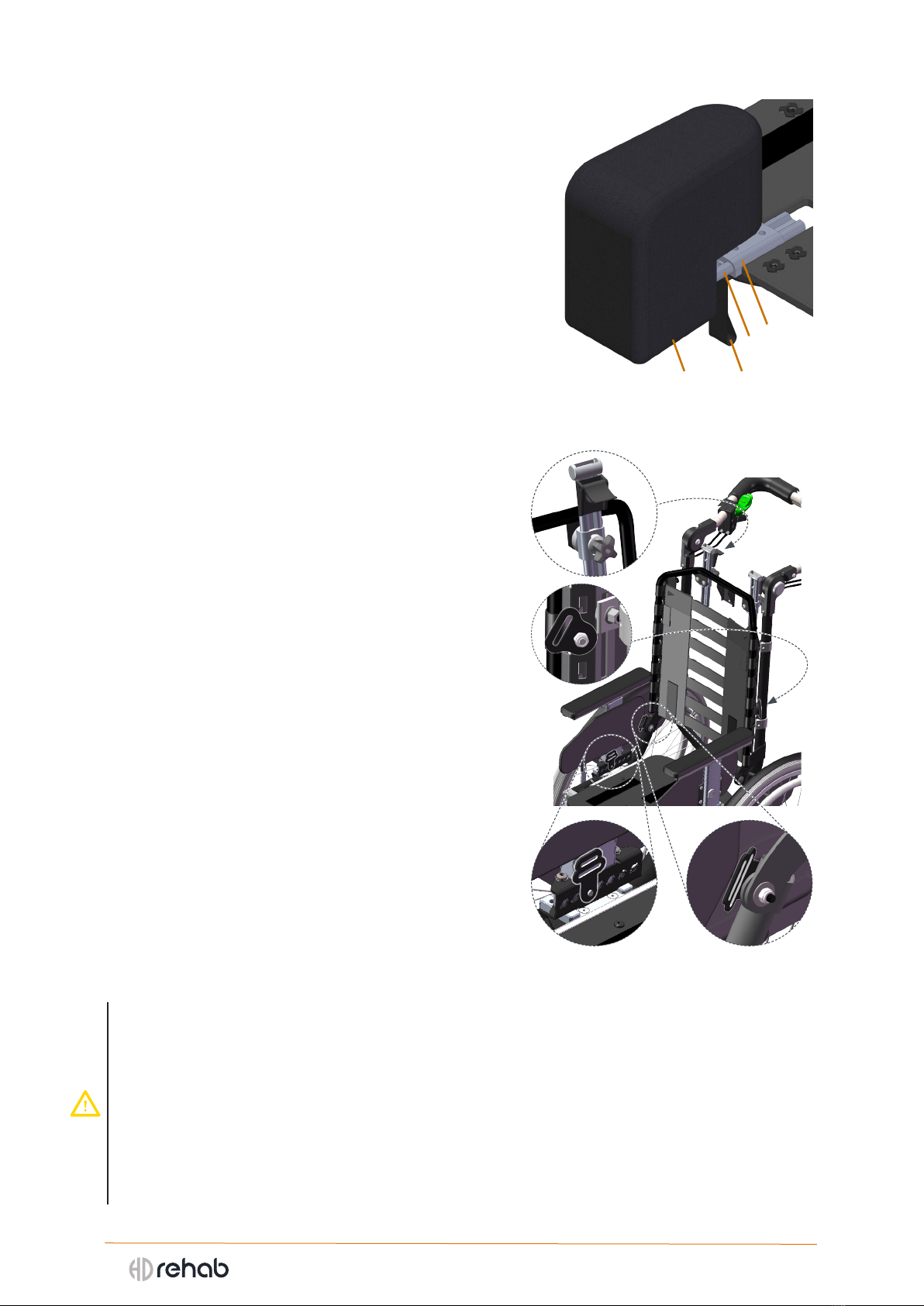
4.6 Mounts for belts and harnesses
If there is a risk that the user can slide out of the wheelchair
a positioning belt and harness can be used. HD Motion can
be equipped with belt mounts at the thighs (1 in Figure 36)
and hips (2), and mounts for harnesses (3 and 4).
MOUNTS FOR 2POINT BELTS
2-point belts are attached to two belt mounts, one on each
side. The mounting points can be at the thighs or at the hips,
depending on the needs of the user. It is important that the
mounts be placed correctly so the the user is well positioned.
They should be installed by qualied personnel. The belt
mounts at the thighs are adjustable 6 cm in 7 positions.
MOUNTS FOR 4POINT BELTS
4-point belts are attached to four belt mounts, two on each
side. It is important that the mounts be placed correctly so
the the user is well positioned. They should be installed by
qualied personnel.
MOUNTS FOR HARNESSES
Harnesses are attached to two adjustable mounts at the top
of the back, together with the two mounts secured in the
lower holes on the sides of the backrest system. It is important
that the mounts be placed correctly so the the user is well
positioned. They should be installed by qualied personnel.
- There may be local restrictions on use of belts.
- Individual information about the use of a belt must be received from the prescriber for each user.
- Be alert when using of positioning belt or harness. There is a risk of the user sliding down in the chair and
getting stuck in the belt if it is incorrectly installed or poorly fastened. This can lead to impaired blood or
oxygen supply and risk of the user choking.
- Always make sure that the belt is securely fastened when in use.
- If possible, tighten the belt with the user in an upright position. If the belt is tightened when the back is
reclined there is a risk of pinching when the back is raised up.
- Be aware of loose belts, they can get caught in the wheels and cause a sudden stop or pinching.
- A harness is always used in combination with a positioning belt.
Figure 35. Knee spacer components
(seat plate also shown)
Figure 36. Belt and harness mounts
3
4
1 2
3
1 2
4
19
HD Motion | User Manual
5. TRANSPORT
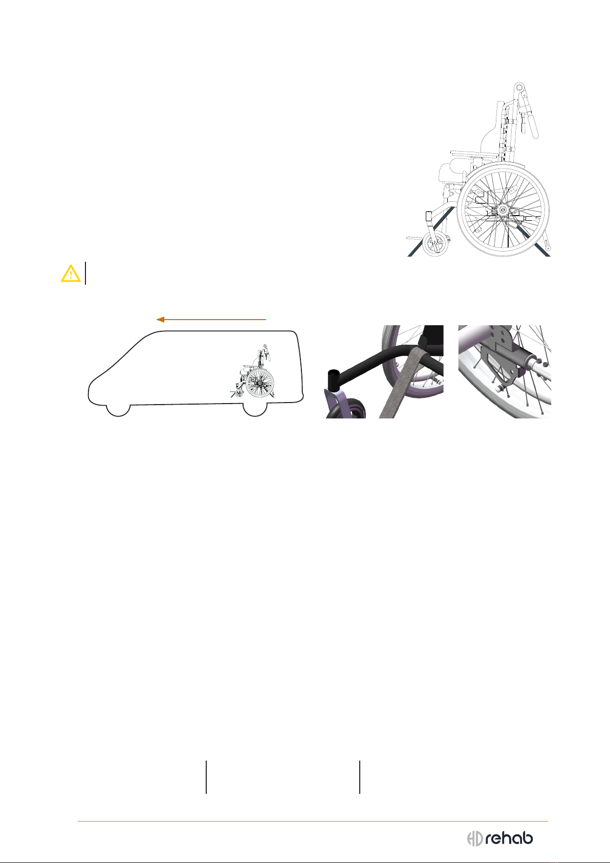
5.1 Vehicle transport with user seated in wheelchair
When transporting in a vehicle HD Motion must be xed in place with
a 4-point belt system (Figure 37) and the user must use the vehicle’s
3-point safety belt. Both must be approved per ISO 10542-2. All
transportation must be done with the wheelchair facing forward, see
Figure 38.
When axing, the rear tension devices are attached to the intended
anchor points on the wheel frame, see Figure 40. The front tension
devices are attached around cross bar of the wheel frame, see Figure
39. These attachment points are marked with the symbol described in
section 2.7 Symbols and markings.
- No other attachment points than those specied may be used.
THE FOLLOWING MUST BE CONSIDERED BEFORE TRANSPORT:
- Tray table, thoracic support, and other accessories must be removed.
- The headrest must be used.
- The seat of the wheelchair should be tilted 5-10° back and the backrest should be slightly reclined
(approximately 100°).
- The wheelchair leg rests must be angled down as much as possible.
- Do not use excessive tension. Tensioners should only be tightened so that the wheelchair is stable.
Any rocking is not to be oset by tightening the straps tighter. Excessive tension creates excessive
stress on the wheels and frame and can damage the wheelchair.
- The user must always use the vehicle’s 3-point safety belt. Any positioning or safety belts that are
mounted on the wheelchair and are usually used by the patient may not be used as substitutes for
seat belts when traveling in vehicles.
HD Motion has been crash tested according to ISO 7176-19 section 5.2, which means that it has been
tested and passed the requirements of a standard test. The test simulates a frontal collision at 48
km/h with a test dummy weighing 59 kg. The standard species minimum requirements for what the
wheelchair must withstand regarding transport in a vehicle.
As an actual incident is likely to be dierent from than the exact conditions in testing, HD Rehab
cannot take any responsibility for the outcome of an accident in which HD Motion is involved.
5.2 Weight of removable components
Wheel 22” (1 pc) 1,8 kg One-piece foot rest 1,8 kg Seat cushion ca 0,5 kg
Armrest (1 pc) 0,8 kg Separate leg rest (1 pc) 1,2 kg Back cushion ca 0,7 kg
Figure 38. All transport must be forward-facing Figure 39. Front
anchor point
Figure 40. Rear
anchor point
Figure 37. Wheelchair xed
in place with belt system

20
HD Motion | User Manual
5.3 Folding the wheelchair for transportation
FOLDING OF WHEELCHAIR
- Tilt the seat unit to its most forward position.
- Remove the armrests and any accessories such as thoracic support and
pommel, as well as cushions.
- Remove the leg rests (optional).
- Grasp the push bar with one hand and pull the locking pin, (1 in Figure
41). The gas spring (2) will then drop down from the mount (3) and the
back can be folded forward against the seat, see Figure 42.
- Fold the push bar down against the back.
- The driving wheels may be removed to make the wheelchair smaller.
REASSEMBLY AFTER FOLDING
- Fold the push bar up.
- Raise the back.
- Pull the locking pin (1), and t the gas spring in the mount.
- Release the locking pin and see that it passes through the gas spring
mounting hole and both plates of the bracket (3 in Figure 41).
CHECKLIST AFTER TRANSPORTATION:
- Make sure the locking pin (1) goes completely through the bracket, see
Figure 39.
- Check that the wheels are securely fastened.
- Make sure the tip protectors are positioned correctly.
- Check the most important functions; brakes, seat tilt, and back recline.
- If the pin is not properly mounted, the bracket can break and the user
can be suddenly tipped backwards.
- If the seat width is set to the widest position there is a risk of the Flexi
back straps wrapping around the seat plate when the chair is folded.
Check for this and be careful when folding the wheelchair up again.
5.4 Transferring in and out of the wheelchair
Transferring in and out of the wheelchair can be done in dierent
ways depending on the user’s ability to actively participate. It can be
done with a lift, with help of one or two caregivers, or independently.
- The brakes must be locked before transferring in or out.
- Remove or fold in leg rests fully so they do not hinder. If
needed foot plates can be folded up.
- Seat tilt and back recline may need to be adjusted per the
particular needs of the user.
- Caregivers need to be mindful of their ergonomic
positioning when assisting.
Figure 41. Locking pin
for folding back rest
Figure 42. Folded wheelchair
Figure 43. Transfer with lift
Figure 45. Independent transferFigure 44. Transfer with assistance
1
3
2
This manual suits for next models
2
Table of contents
Other HD Rehab Wheelchair manuals

HD Rehab
HD Rehab 95171-1 User manual

HD Rehab
HD Rehab Push bar User manual

HD Rehab
HD Rehab HD Balance 62471 User manual

HD Rehab
HD Rehab 95827 User manual

HD Rehab
HD Rehab Motion 15680 User manual

HD Rehab
HD Rehab 56904 User manual

HD Rehab
HD Rehab HD Balance 24 User manual

HD Rehab
HD Rehab HD motion 69760 User manual

HD Rehab
HD Rehab 69351 User manual

HD Rehab
HD Rehab 69620 User manual


