Stealth mo-Vis Series User manual

USER MANUAL
Power Chin Boom
Stealth’s mo-Vis Series Versatile Powered
Mounting Device
Alternative Drive Controls

i
Customer Satisfaction 1.0
Stealth Products strives for 100% customer satisfaction. Your complete
satisfaction is important. Please contact us with feedback or suggested
changes that will help improve the quality and usability of our products.
You may reach us at:
General
The Power Chin Boom Mounting Hardware is intended to be fitted on any
power wheelchair with 24 V connections.
Incorrect use or installation may lead to risk of injury to the user and damage to
the wheelchair or other property.
Read and understand all instructions prior to the use of the product. Failure to
adhere to instructions and warnings in this document may result in property
damage, injury, or death. Product misuse due to failure of the following
instructions will void the warranty.
Immediately discontinue use if any function is compromised, parts are missing,
loose, or shows signs of excessive wear. Consult with your supplier for repair,
adjustment, or replacement.
The Power Chin Boom Motor Unit is a non-serviceable part.
MDSS GmbH
Schiffgraben 41
30175 Hannover, Germany
Stealth Products, LLC
104 John Kelly Drive, Burnet, TX 78611
Phone: (512) 715-9995 Toll Free: 1(800) 965-9229
Fax: (512) 715-9954 Toll Free: 1(800) 806-1225

ii
Important Information 2.0
Important Information!
All persons responsible for fitting, adjustment, and daily use of the devices
discussed in these instructions must be familiar with and understand all safety
aspects of the devices mentioned. In order for our products to be used
successfully, you must:
Read and understand all instrucons and warnings
Maintain our products according to our instrucons on care and maintenance
Devices should be installed and adjusted be a trained technician
Supplier Reference
Supplier:
Telephone:
Address:
Purchase Date:
Model:

iii
Introduction 3.0
Before you install or begin using this product, it is important that you read and
understand the content of these installation and operating instructions.
The installation instructions will guide you through the options and possibilities
with the product. Stealth’s mo-Vis Series Power Chin Boom Hardware should be
adjusted with the mo-Vis Configurator Software.
Instructions are written with the expressed intent of use with standard
configurations. They also contain important safety and maintenance
information, as well as describe possible problems that can arise during use. For
further assistance, or more advanced applications, please contact your supplier
or Stealth Products at (512) 715-9995 or toll free at 1-800-965-9229.
Always keep the operating instructions in a safe place so they may be
referenced as necessary.
All information, pictures, illustrations, and specifications are based on the
product information that was available at the time of printing. Pictures and
illustrations shown in these instructions are representative examples and are
not intended to be exact depictions of the various parts of the product.
Ordering Documentation
You can download additional copies of this user manual for mounting the Power
Chin Boom and the associated hardware on the Stealth website:
https://stlpro.site/stealth-docs
and search: mo-Vis Power Chin Boom User Manual in the search bar at the top of
the page.

iv
Warranty
Our products are designed, manufactured, and produced to the highest of
standards. If any defect in material or workmanship is found, Stealth Products
will repair or replace the product at our discretion. Any implied warranty,
including the implied warranties of merchantability and fitness for a particular
purpose, shall not extend beyond the duration of this warranty. Stealth
Products, LLC does not warrant damage due to, but not limited to:
Misuse, abuse, or misapplicaon of products.
Modicaon or product without wrien approval from Stealth Products, LLC.
Any alteraon or lack of serial number, where applicable, will automacally
void this warranty.
Stealth Products, LLC is liable for replacement parts only.
Stealth Products, LLC is not liable for any incurred labor costs.
No person is authorized to alter, extend, or waive the warranties of Stealth
Products, LLC.
Stealth Products warrants against failure due to defective materials
or workmanship:
Covers: 2 years
Hardware: 5 years
Electronics: 3 years
In Case of Product Failure
In the event of product failure covered by our warranty, please follow the
procedures outlined below:
1. Call Stealth at +1 (512) 715-9995 or toll free +1-800-965-9229.
2. Request the Returns Department or obtain an RA from the Returns Department and
follow department or documentaon instrucons.

v
Table Of Contents 5.0
1.0 Customer Satisfaction..............................................................................i
2.0 Important Information ...........................................................................ii
3.0 Introduction.............................................................................................iii
4.0 Warranty ..................................................................................................iv
5.0 Table Of Contents....................................................................................v
6.0 Warning Labels .....................................................................................viii
6.1 Warning Labels......................................................................................................viii
6.2 Limited Liability .....................................................................................................viii
6.3 Testing ......................................................................................................................viii
7.0 Design And Function Of The Power Chin Boom.................................1
7.1 Purpose......................................................................................................................1
7.2 Features......................................................................................................................1
7.3 Available Versions..................................................................................................1
8.0 Parts And Accessories .............................................................................2
8.1 Power Chin Boom Package ................................………………….……………..….2
8.2 Complete Installation ...........................................................................................4
8.3 Power Chin Boom Motor Unit Detail .............................................................4
8.4 Custom Configurations........................................................................................4
9.0 Installation Instructions.........................................................................5
9.1 Qualified Service Technician..............................................................................5
9.2 Tools............................................................................................................................5
9.3 Installation Plan ......................................................................................................5
9.4 Serial Number Sticker...........................................................................................5
10.0 Installation of Power Chin Boom Unit ...............................................6
10.1 Motor Unit Installation ......................................................................................6
10.2 Power Chin Boom Arm Installation ..............................................................7
10.3 Testing .....................................................................................................................8

vi
Table Of Contents 5.0
11.0 Installation of All-Round Mounting Set ..........................................10
11.1 Installing Mounting Set ..............................................................................10
12.0 Defining Movements ........................................................................11
12.1 Defining Parameter Settings.....................................................................11
12.2 Parameter Settings .......................................................................................11
13.0 First Time Use ....................................................................................12
13.1 Dealer Assistance ..........................................................................................12
13.2 User Testing.....................................................................................................12
13.3 Conditions Of Use.........................................................................................13
13.4 User Adjustments..........................................................................................13
14.0 mo-Vis Configurator Software........................................................14
14.1 Software Capabilities ...................................................................................14
14.2 Software Download......................................................................................14
14.3 Installation Possibilities...............................................................................20
14.4 Default Power Chin Boom Motor Unit Placement ...........................20
14.5 Power Chin Boom Arm Positioning .......................................................20
14.6 Connection Options .....................................................................................20
14.7 Operation Options........................................................................................21
14.8 Driver Safety ....................................................................................................21
15.0 Troubleshooting ................................................................................22
16.0 Error Codes.........................................................................................23
17.0 Parameter Settings............................................................................25
17.1 Mounting Settings ........................................................................................25
17.2 Operational Settings ....................................................................................25
17.3 Motor Settings................................................................................................30
17.4 Hardware Settings.........................................................................................31

vii
Table Of Contents 5.0
18.0 Maintenance ......................................................................................34
18.1 Cleaning...........................................................................................................34
18.2 Monthly Check..............................................................................................34
18.3 Power Chin Boom Motor Unit Maintenance.....................................34
19.0 Technical Data .....................................................................................35
19.1 Product Description & Code ....................................................................35
19.2 Interface Connectors....................................................................................35
19.3 Maximum Torque Arm................................................................................35
19.4 Sleep Mode Timer.........................................................................................35
19.5 Power Chin Boom Dimensions ................................................................36
19.6 Voltage Supply...............................................................................................36
19.7 Output Drive Safety Update Time ..........................................................36
19.8 Power Consumption ....................................................................................36
19.9 EMC Requirements.......................................................................................36

viii
Warning Labels 6.0
Warning Labels 6.1
Warnings are included for the safety of the user, client, operator and property.
Please read and understand what the signal words SAFETY, NOTICE, CAUTION,
WARNING and DANGER mean, how they could affect the user, those around
the user, and property.
Limited Liability 6.2
Stealth Products, LLC accepts no liability for personal injury or damage to
property that may arise from the failure of the user or other persons to follow
the recommendations, warnings, and instructions in this manual.
Testing 6.3
Initial setup and driving should be done in an open area free of obstacles until
the user is fully capable of driving safely.
The Power Chin Boom should always be tested without any person sitting in
the wheelchair until every alteration of the physical installation or adjustment
is complete.
NOTICE
Identifies important information not related to injury, but
possible property damage.
SAFETY
Indicates steps or instructions for safe practices, reminders of
safe procedures, or important safety equipment that may
be necessary.
CA UTIO N Identifies a potential situation which (if not avoided) will
result in minor to moderate injury,and property damage.
WARNI NG Identifies a potential situation which (if not avoided) will
result in severe injury, death,and property damage.
DANGER Identifies an imminent situation which (if not avoided) will
result in severe injury, death,and property damage.

1
Design And Function 7.0
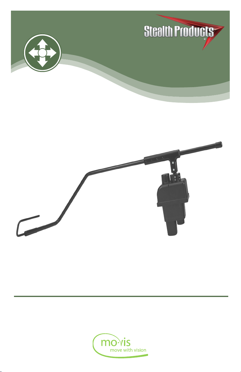
Purpose 7.1
The Power Chin Boom is a versatile, motorized arm to mount on a powered
wheelchair. With this arm, a chin joystick can be positioned to drive. The arm
is programmed to move horizontally or vertically by pressing a button
when needed.
Features: 7.2
The Power Chin Boom is mounted to the back or side of the wheelchair by
attaching compatible brackets to the rear of the chair.
With the included mounng hardware, the Power Chin Boom Motor Unit and arm can be
opmally posioned for each individual user.
With the mo-Vis Congurator Soware, the device’s movements, speeds, and acvaon
methods can be altered for every situaon.
The Power Chin Boom works with any buon with mini jack connecon (stereo or mono).
The jack connecons of the input and output are congurable via computer, e.g. one
input buon can be congured to perform up to three dierent funcons.
Available Versions 7.3
When ordering the Power Chin Boom (IDM-PCB-L or IDM-PCB-R), please specify what
type of chair this will be mounted onto. This will determine which hardware package you
will receive with your order.
Power Chin Boom Package for the Right Side of the chair (IDM-PCB-R): For installaon at
the right side of the wheelchair, comes with right arm. Includes Chin Boom Brackets for
mounng.
Power Chin Boom Package for the Le Side of the chair (IDM-PCB-L): For installaon at the
le side of the wheelchair, comes with le arm. Includes Chin Boom Brackets for mounng.
Chin Boom Bracket Hardware Package- The Power Chin Boom Bracket Hardware comes
with each order of a Power Chin Boom. Please specify what type of chair will be used; this
will determine the hardware package you receive. These packages can be ordered
separately if more parts are needed.
-For a Quantum chair, DBM100-1
-For a Permobil chair, DBM100-2
-For a Cane mount, DBM100-3
1” standard Cane Clamp is provided with this package. If a different size is needed,
please specify when ordering.

2
Parts And Accessories 8.0
Power Chin Boom Package 8.1
The Power Chin Boom package can be ordered for the right side of the chair or the left
side. Each package includes:
Product Description
Power Chin Boom Right Arm
2mm Set Screws included
Power Chin Boom Left Arm
2mm Set Screws included
Power Chin Boom T-Connection
3mm Set Screws included
Power Chin Boom Arm to Rod
Interconnection Assembly
2.5mm Set Screws included
Power Chin Boom T-Bar Connection
Power Chin Boom Motor Unit with
i-Connect Power Source
2.5mm Set Screws included
Power Chin Boom C-Rod
Power Chin Boom S-Rod
Power Chin Boom Pulling Wire
Power Chin Boom End Stop

3
Parts And Accessories 8.0
The All-Round Mounng Set (IDM-46) is REQUIRED if mounng the All– Round Joysck to
the Power Chin Boom.
Additional Items: Product Description Product Code
All-Round Joystick
Mounting Set (for mounting
All-Round Joystick only)
IDM-46
Product Description Package #
Track/Cane Chin Boom DBM100-1
Front Rotation Chin Boom
Mount
DBM100-1
DBM100-2
DBM100-3
Back Track Chin Boom Mount DBM100-2
Chin Boom Extension Straight DBM100-1
DBM100-2
DBM100-3
Track/Cane Chin Boom Slide DBM100-1
DBM100-2
DBM100-3
Chin Boom Extension Angled DBM100-1
DBM100-2
DBM100-3
1” Cane Clamp DBM100-3
Universal 2GTR Lateral
Nut–Metric
4mm T-Handle Required
DBM100-2
T-Nut Metric
4mm T-Handle Required
DBM100-1
The Dog Bone Bracket Package is included with each order of a Power Chin Boom
Right/Left Package. Depending on the chair being used, certain brackets will
be included.

4
Parts And Accessories 8.0
Complete Installation 8.2
Below, you see a picture of a completely installed Power Chin Boom Arm, ready to be
mounted to the brackets on a chair.
A torque limiter is installed within the motor unit housing. When the torque becomes too
high, the limiter is released.
The arm can be “shied” out of its locaon when too much torque is being placed on it.
This should have no eect on the posion or mechanical stop of the arm when it is in use.
Power Chin Boom Motor Unit Detail 8.3
The connections of the Power Chin Boom Motor Unit have protective inserts to avoid
the intrusion of dust or moisture during usage. An i-Connect power source is attached
to the motor unit for connection to a Quantum or Permobil chair.
Custom Configurations 8.4
Stealth has the ability to create custom configurations for the desired
mounting hardware.

5
Installation Instructions 9.0
CAUT ION
Always put or keep the protective cover in case the connections are not used.
Qualified Service Technician 9.1
Only a qualified service technician may install the Power Chin Boom.
Tools 9.2
T-Bar Connecon- 3mm T-Handle
Arm to Rod Interconnecon- 2.5mm T-Handle
Arm-2mm T-Handle
Motor -2.5mm T-Handle
CAUT ION
Use the proper tools to install and adjust the Power Chin Boom. The use of improper
tools may cause damage to the device.
CA UTIO N Do not tighten screws with excessive force.
Installation Plan 9.3
Set up an installation plan before starting the installation. Based on the users’ needs
and with actual measurements of the wheelchair and the user, this plan should specify:
Where each part of the Power Chin Boom should be placed.
How the Power Chin Boom will be operated.
The Power Chin Boom Motor Unit parameter sengs.
Serial Number Sticker 9.4
The additional serial number sticker (included in the package) has to be adhered to the
back of this manual.
NOTICE
Before inserting a connector, remove the protective cover.
CA UTIO N Any connection must always be secured with supplied screws.

6
Installation Of Power Chin Boom Unit 10.0
Motor Unit Installation 10.1
To install the Power Chin Boom Motor Unit, carefully follow the directions of this manual.
To install the Power Chin Boom Mounting Hardware, follow the instructions in the
correlating installation manual.
Depending on the needed placement of the Power Chin Boom, angle and height
adjustments can be made to the hardware.
If more hardware is needed, the Chin Boom Brackets can be ordered as a separate
package. Please call Stealth Products for more information.
CAUT ION
The connections must be at the bottom (default position) or at the lower part
(tilted position).
CA UTIO N The mount must be inside the wheelbase.
Lead the i-Connect Power Source Connector to a fused connection on the wheelchair
battery and secure the i-Connect Power Source Connector to the wheelchair.
An IC24PS-QL or IC24PS-RN is required in order to connect from the power source to the
chair. Please specify when ordering which connector you will need.
WARNI NG
Do not connect the i-Connect Power Source Connector to the wheelchair battery or
another battery source while installing or adjusting the Power Chin Boom Motor Unit or
Power Chin Boom Arm to avoid any unwanted movement.

7
Installation Of Power Chin Boom Unit 10.0
Power Chin Boom Arm Installation 10.2
Make sure the Power Chin Boom Motor Unit is properly installed before starting
installation of the Power Chin Boom Arm. The Motor Unit contains 2.5mm set screws.
CAUT ION
Any connection must always be secured with all delivered screws. Only use the screws
provided in the package.
To install the arm, proceed as follows according to your installation plan:
Insert the Power Chin Boom T-Bar Connecon into the motor unit. Adjust and secure
with provided set screws.
Aach the T-connecon to the T-Bar Connecon. Aach and secure with
provided set screws.
Insert the Power Chin Boom Right or Le Arm into the T-connecon. Adjust arm to
desired length and secure with set screws.
Place and secure Arm to Rod Interconnecon Assembly at the end of the arm.
Place C-Rod or S-Rod into end of the Arm to Rod Interconnecon Assembly. Adjust angle
and secure with provided screw. Choose the rod that best ts your clients needs.
CAUT ION
Select the appropriate screw location in the T-connection. Screws should be placed in
such a way that they do not enter the cable throughputs in the arm.
NOTICE
If needed, cut off excessive piping at the back of the arm (behind the T-connection).
Remember to keep a small excess of piping off the back in order to make readjustments.
SAFETY
By removing excess piping, this can reduce the risk of objects becoming hung or stuck.
This will also ensure safety during transfers.
NOTICE
There is play in the arm when it is not in the end position.
NOTICE
The screws on the Power Chin Boom need to be tightened regularly.

8
Installation Of Power Chin Boom Unit 10.0
To install the joystick onto the Power Chin Boom, follow the
provided Instructions:
Remove screws from the base of the interface and open interface box. Carefully
disconnect the joysck cable from the interface.
Insert pulling wire at base of arm and feed unl you have reached the top of the arm. The
end of the wire with the hook should be inserted rst.
Use the pulling wire to insert the connecon cable for the device into the arm at the top.
Carefully pull down on wire and feed through unl the cable is through the nal slot in
the arm.
The connecon cable enters at the C-Rod or S-Rod and leaves the arm just past the
T-connecon.
Place the device on the C-Rod or S-Rod in the desired locaon and secure it rmly.
CAUT ION
The maximum device weight is 500gr at a distance of 25.59in. (650mm) from the pivot
point at the Power Chin Boom Motor Unit connection.
Reaach and secure the joysck cable to the interface.
Use screws to carefully screw interface box back together. Do not overghten screws.
Mount the end stop.
Testing 10.3
After installation of the Power Chin Boom Motor Unit and the Power Chin Boom Arm,
test the positioning and movements of the arm.
WARNI NG First, test without any person sitting in the wheelchair.
CAUT ION
Always use a fused connection of maximum 15A on the wheelchair battery.
Connect the Power Chin Boom Motor Unit to the wheelchair baery with the i-Connect
Power Source Connector.
NOTICE
Disconnecting and reconnecting cable from the interface will NOT
void the warranty.

9
Installation Of Power Chin Boom Unit 10.0
Connect a button* to the Power Chin Boom Motor Unit steering input.
Power up the wheelchair.
Push the button.
Default Power Chin Boom Motor Unit parameter settings are:
Open/Close Arm, Momentary (arm moves as long as the buon is pressed, pressing
again changes the direcon of the movement).
Check the following items:
Is the arm moving in accordance with the default sengs?
Can the arm move freely without hindering any wheelchair item or cable?
Can the arm move without hindering a person in the wheelchair?
Can all cables move freely while being securely aached?
If needed, adjust the positioning of the arm and Power Chin Boom Motor
Unit and retest until optimal and secure functioning.
* A Black Egg Switch is included with each Power Chin Boom order. This switch will activate move-
ments of the arm.
WARNI NG
Switch off the wheelchair and disconnect the Power Chin Boom Motor Unit
from the power source to avoid any unwanted movement.
CA UTIO N Check that all screws are firmly secured.

10
Installation Of All-Round Mounting Set 11.0
Installing Mounting Set 11.1
1. Dene the posion of the joysck.
When the USB connecon points toward the user, a forward movement of the joysck
will result in a forward movement of the wheelchair. If needed, you can change
this posioning in steps of 90° with the mo-Vis Congurator Soware.
2. Determine which of the 2 slots you will user to guide the cable.
3. Place the 2 M5 locknuts in the rst Mounng Plate.
4. Secure the Mounng Plate with the 4 M5 bolts to the base of the joysck housing.
5. Place the adaptor 6mm mounng set on the rod.
6. Secure the Mounng Plate with the 2 M5 bolts.
The All-Round Mounng Set (IDM-46) is sold separately and is only required for mounng
the All-Round Joysck to the Power Chin Boom.
CAUT ION
Tighten the screws firmly, but not excessively. Excessive force may damage the unit.
NOTICE
The All-Round Joystick cable will not feed through the arm of the Power Chin Boom.

11
Defining Movements (Parameters) 12.0
The Power Chin Boom movement, speed, angle, and connection are fully
adjustable with the mo-Vis Configurator Software.
This soware must be installed and is ready to use on a pc.
Depending on your user prole (User, Aendant, Dealer, OEM), you will be able to
change a number of parameter sengs.
To dene the movements during the installaon procedure, we advise having at
least a dealer prole.
Defining Parameter Settings 12.1
To define the parameter settings, proceed as follows:
Connect the Power Chin Boom Motor Unit to a pc. Use a standard mini-USB cable.
Congure the parameters with the soware.
Upload the conguraon.
Test the conguraon and adjust if necessary.
Parameter Settings 12.2
Please see “Settings” for a list of all parameter settings (Section 17.0).
The mo-Vis Congurator Soware is oponal to download. The joysck and its sengs can
be congured through the chair’s display.
Other manuals for mo-Vis Series
1
This manual suits for next models
3
Table of contents
Other Stealth Wheelchair manuals
Popular Wheelchair manuals by other brands

Rehab
Rehab HD Balance User manual & assembly instructions

Invacare
Invacare 9000 series Owner's operator and maintenance manual

Pride Mobility
Pride Mobility IGO Fold owner's manual

Specialised Orthotic Services
Specialised Orthotic Services Miko user manual

Days
Days VERB user manual

Valex
Valex M-MU 18-MULTI ONE instruction manual