User manual - Zitzi Guppy I 4© Anatomic SITT AB
Safety precautions 3
Introduction 3
Seat part 6
Mounting of the seatplate 6
Tilt 7
Tilt of the seat 7
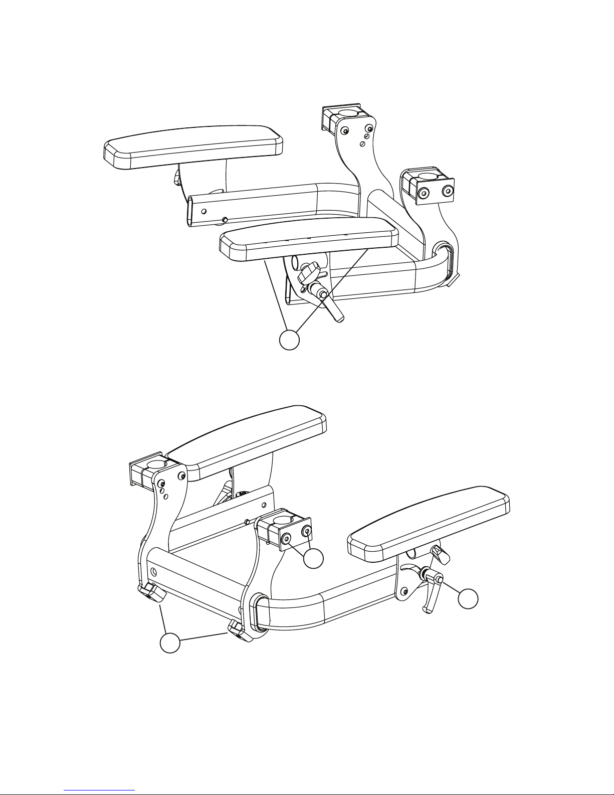
Armrest 9
Installation on chassis 9
Height adjustment 9
Width adjustement 9
Angle adjustment upwards and downwards 9
Depth adjustment 9
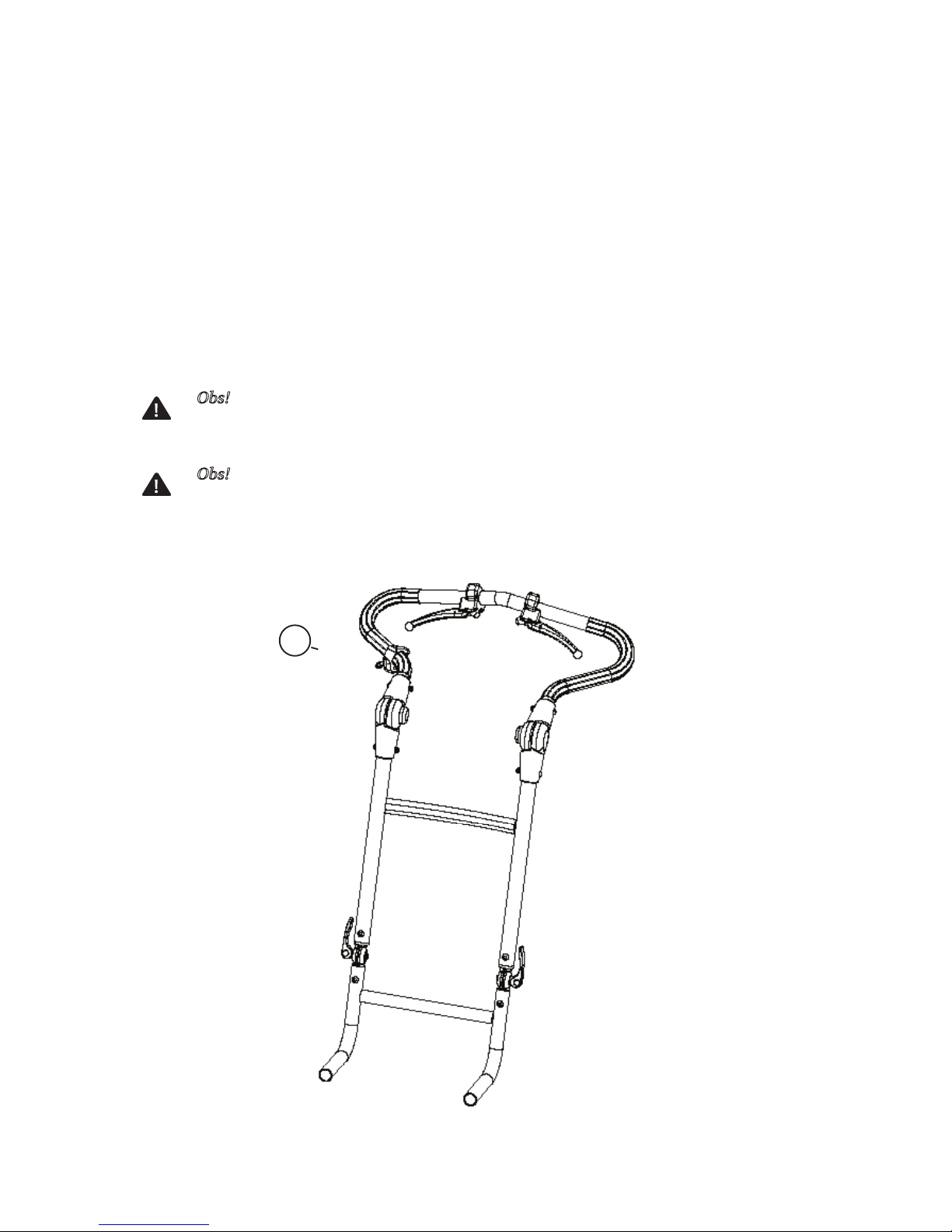
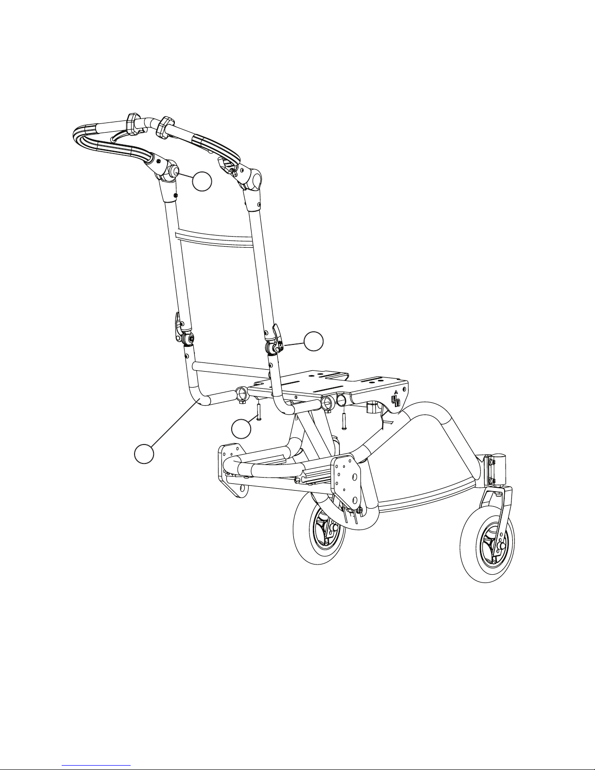
Driving-handle 11
Installation of driving-handle 11
Depth adjustment of the driving-handle 11
Angle adjustment of the driving-handle 11
Angle adjustment of driving-handle 11
Fold the driving-handle 11
Wheels with Quick-release 12
Mounting of wheels with quick-release 12
Release the wheel 12
Driving wheels 13
Wheel position 13
Caster 14
Installation of caster 14
Mounting of the caster on the caster house fork 14
Caster positioning 14
Caster fork position 15
Angle adjustment of caster fork 15
Brake 17
Drum brake 17
Setting the brakes 17
Releasing the brakes 17
Troubleshooting of the brakes 17
Installation of drum brake 19
Parking brake 20
Installation of parking brake 20
Using the parking brake 20
Footrest 21
Mounting of footrest 21
Safety stop 21
Adjusting the angle on the knee-joint 21
Adjustment the height of the footrest 21
Calf support 22
Mounting of calf support 22
Height adjustment of the calf support 22
Width adjustment of the calf support 22
Anti-tip device 23
Installation of anti-tip device 23
Using the anti-tip device 23
Step bar 24
Installation of the step-bar 24
Using the step-bar 24
Transportation kit 26
Installation of front bracket 26
Installation of rear bracket 26
Installation of safety-loop 26
Using the transportation kit 26
Direction lock 28
Install the direction lock 28
Activate direction lock 28
Releasing the direction lock 28
Table of contents