HDI 1522 User manual

HDI 1522/2522 POSITION INDICATOR
GAUGE
User’s Manual Rev B

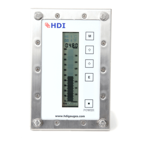
HDI 2522 Position Indicator Gauge
User’s Manual – HDI 2522, Rev B | May 2022
2
Table of Contents
Section 1 – Introduction ..................................................................................................................................... 4
1.A General Information ........................................................................................................................... 4
1.B Unpacking and Inspection ................................................................................................................ 4
1.C Cautionary Information..................................................................................................................... 5
Section 2 – HDI 2522 Series Position Indicating Gauge Systems Overview ................................... 6
2.A System Overview ................................................................................................................................. 6
2.B Accuracy .................................................................................................................................................. 7
2.C Control Head .......................................................................................................................................... 7
2.D Potentiometers ..................................................................................................................................... 7
2.E Cable ......................................................................................................................................................... 8
2.F System Options ..................................................................................................................................... 8
2.G Certification ........................................................................................................................................... 9
Section 3 – Installation ........................................................................................................................................ 9
3.A Control Head 2522 .................................................................................................................................. 9
3.B Cables and Routing .......................................................................................................................... 10
Section 4 – Gauge Functions .......................................................................................................................... 10
4.A Overview .............................................................................................................................................. 10
4.B Gauge Head Features ...................................................................................................................... 11
4.C Engineering Units Display ............................................................................................................. 11
4.D Main Display ....................................................................................................................................... 11
4.E Bar Graph Display............................................................................................................................. 11
4.F Membrane Panel ............................................................................................................................... 11
4.G Power Off / On Button ................................................................................................................... 11
4.H Mode (M) Button Calibration Only ............................................................................................ 11
4.I Up () Button .................................................................................................................................... 12
4.J Down () Button.............................................................................................................................. 12
4.K Enter (E) Button ................................................................................................................................ 12
Section 5 – Gauge Operation .......................................................................................................................... 12
5.A Gauge Operation Overview ........................................................................................................... 12
5.B Run Mode ............................................................................................................................................. 12
Section 6 – Maintenance .................................................................................................................................. 14
6.A Cleaning ................................................................................................................................................ 14

HDI 2522 Position Indicator Gauge
User’s Manual – HDI 2522, Rev B | May 2022
3
6.B Power Pack .......................................................................................................................................... 14
6.C Processor Boards .............................................................................................................................. 15
6.D Potentiometers .................................................................................................................................. 15
Section 7 – Troubleshooting .......................................................................................................................... 15
7.A Battery Voltage .................................................................................................................................. 15
7.B Additional Troubleshooting ......................................................................................................... 15
Section 8 - Installation Configurations ...................................................................................................... 16
Section 9 - Cable Connection Drawing ....................................................................................................... 22
Section 10 - Gauge Mounting Diagram ...................................................................................................... 23
Section 11 – Potentiometer Configurations ............................................................................................. 24
Section 12 - Certification Markings ............................................................................................................. 27
Section 13 - IECEX Certificate........................................................................................................................ 28
Section 14 - ATEX Certificate ......................................................................................................................... 31
Section 15 - CSA Certificate ............................................................................................................................ 34
Section 16 - Warranty ...................................................................................................................................... 38

HDI 2522 Position Indicator Gauge
User’s Manual – HDI 2522, Rev B | May 2022
4
Section 1 – Introduction
1.A General Information
This manual describes the installation, operation, and maintenance of the HDI 1522 and 2522 Position
Indicator Gauge Systems. The 1522 Series products includes HDI’s Calibration Certificate and
Certificate of Compliance. The 2522 Series products include the third-party approval (ATEX / IECEx /
CSA) along with HDI’s Calibration Certificate and Certificate of Compliance.
For brevity, we will use the name "2522" to refer to both the 1522 and 2522 products. The 1522 and
2522 Series unites are identical for purposes of this user’s manual, unless noted otherwise (E.G., third-
party approvals).
The HDI 2522 is an industrial position indicator gauge designed for use in explosive atmospheres. The
2522 is a 4-inch panel mounted gauge with remote sensor connections. The 2522 gauge system is
powered by a replaceable battery pack HDIBATT-E608-DOT-AA and can be optionally provided with
various configurations for user feedback and connection to other indicator gauges. See section 8 HDI
installation configuration drawings.
This manual describes the installation, operation, and maintenance of the HDI 2522 gauge system.
This manual will provide the user with all the necessary information to properly inspect, install, operate
and perform routine maintenance and troubleshooting for onsite repairs.
The HDI 2522 has three key elements: the control head, a sensor assembly specified by the end client,
and the cable assembly connecting the control head to the sensor assembly. These items will be
discussed at greater detail in Section 2.
1.B Unpacking and Inspection
Upon receipt of the equipment, it is critical to confirm all the necessary items are accounted for as some
items can settle to the bottom of the box. In the past, some items have inadvertently been removed
from packaging by freight forwarders or third party (Custom agents) during transit. The customer should
compare the packing list against items located within the packaging. If a discrepancy exists, the
customer is advised to first contact their shipping agent and then HDI if the items have not been located.

HDI 2522 Position Indicator Gauge
User’s Manual – HDI 2522, Rev B | May 2022
5
1.C Cautionary Information
1.C.1 Power
This system is powered by an internal power pack HDI part number HDIBATT-E608-DOT-AA. The
2522 gauge will be damaged if connected to a 12 or 24VDC system. Note that the battery should
only be replaced while in a non-hazardous area.
1.C.2 Exposed Electronics
CAUTION: Do not leave the equipment exposed to outside elements without being properly
connected as this may expose the connector leads to moisture and outside elements damaging the
electronics.
1.C.3 Cleaning
CAUTION: The customer should use caution when cleaning the Gauge (LCD) Head to prevent any
static discharge. From time to time the customer will need to use a damp cloth to clean the LCD overlay
or the gauge case. HDI suggests that the customer use a soft cloth to prevent accidental damage
(scratching) to the protective lens.
1.C.4 Returns
HDI requires that inbound returns should have a Return Material Authorization (RMA) control number
issued from the HDI website. The customer will find this by visiting the website:
http://hdigauges.com/quality/repairs/ and complete the required fields to identify basic contact details.
HDI will then provide the customer repair return quotation and will contact the customer for additional
clarity if necessary. The customer may return multiple units on one RMA submittal request. HDI will
use the inbound notification email for all related correspondence. Proper protection of the equipment
should be a top priority when returning the equipment back to HDI or an authorized agent for repair.
Additionally, it is the shipper’s responsibility to ensure equipment clears all customs as different
agencies may hold equipment without notifying HDI.

HDI 2522 Position Indicator Gauge
User’s Manual – HDI 2522, Rev B | May 2022
6
1.C.5 Personnel Qualifications
CAUTION: Anyone testing the equipment should have basic electrical understanding, knowledge
of circuitry, and use of a multi-meter. The customer should read the entire manual prior to opening the
display or testing. Any modifications to the HDI 2522 system will void the one year warranty and
jeopardize the IECEX certifications.
Section 2 – HDI 2522 Series Position Indicating Gauge Systems
Overview
2.A System Overview
The HDI 2522 position indicator gauge is a standalone and intrinsically safe electronic indicator gauge
system powered with the HDI field replaceable internal 3.6 Vdc power pack. This battery provides the
power to run the internal circuitry of the gauge assembly, including its display and microcontroller. The
internal battery does not provide the power to drive the 4-20 mA loop (if equipped). The indicator
gauge system requires minimal power during normal operation. The gauge is designed for continuous
operation but can be turned off by the user if desired. The gauge will retain its calibration information
even when powered down. The battery life is guaranteed for one year of continuous operation.
All HDI position indicator gauge Displays are comprised of a liquid crystal display (LCD) display that
includes both a numeric (5 digit) representation (for accuracy) and a bar-graph representation (for
trend) and low battery alarm indicator.
The 2522 gauge system will enable the user to have either a 4-20mA output signal (as an added option)
for chart recording or PLC integration or with the ability to have a slave gauge display to repeat the
same position reading at a different location. The HDI 2522 is configured to allow for a maximum of
two slave gauge displays in addition to the master.
The 2522 gauge systems are shipped as matched and calibrated systems, comprised of the gauge
head and potentiometer assembly. The potentiometer assembly is matched to the head appropriately
and both serialized. Once calibrated, are a matched set.

HDI 2522 Position Indicator Gauge
User’s Manual – HDI 2522, Rev B | May 2022
7
2.B Accuracy
HDI 2522 gauges are factory calibrated to measure and display the exact position of the item that is
being monitored to a tolerance of 1 percent full scale (FS) Each gauge system is shipped with the
signed and witnessed factory calibration test sheets.
2.C Control Head
The HDI 2522 gauge has a 4-inch diameter LCD face providing a bar graph and is supplied with
numeric digits at the bottom of the LCD for quick glance reading. Some adjustments may be necessary
depending upon location and mounting methods to take into account deck lighting and overhead
sunlight conditions. See Section 10 for mounting dimensions.
When preparing or deciding upon a location for mounting, the customer should consider the
interconnecting cable and the access route to attach or remove the cable from the gauge. HDI
recommends having a minimum of four inches of clearance for cable bend allowance from the bottom
edge of the case. See Section 10 for cable clearance details. Alternatively, the customer may request
custom specific cables (in increments of 5 feet) with 90 degree mating connectors if spacing is limited.
These would face directly to the rear of the gauge. For enclosed control panel applications, HDI
suggests a bulkhead access plate on the side so the interconnect cables to the gauges can be pre-
routed. This would allow for plug and play installation with the inline cable coming from the sensors.
2.D Potentiometers
The HDI 2522 gauge comes with several different sensor housings to be compatible to various mount
styles to reduce onsite customization and to simplify installation after removing the existing pneumatic
sensors. This device is specifically matched to the gauge’s control head and is tracked with
corresponding serial numbers that allows HDI to track repair history and specific configuration
requirements. It is important for the customer to properly retain their serial number records for more
efficient support by HDI. The 2522 gauge can be supplied with various potentiometer housing options:
See related connection types in Section 11. General dimensional drawings or photos are also available
upon request to ensure compatibility.

HDI 2522 Position Indicator Gauge
User’s Manual – HDI 2522, Rev B | May 2022
8
CAUTION:
Use of non-HDI approved potentiometers could severely damage the instrument and voids the
standard HDI one year warranty.
Replacement or substitution of the potentiometer will require the user to recalibrate the gauge
to the new sensor based on the indication required range. Customer to review calibration
procedures in Section 5.C.2 or may visit: http://hdigauges.com for more details.
2.E Cable
To better serve HDI’s clients, interconnect cables are ordered in 5-foot increments only. In the event
the customer receives their specified interconnect cable only to find that it is too short, the customer
can order an additional inline cable. This is basically an extension cable with corresponding Male /
Female connectors for a plug and play installation.
2.F System Options
HDI offers various options as listed in the following subsections. The customer must use the installation
drawings listed in Section 8 to connect the HDI 2522 gauge from a hazardous to a non-hazardous
zone. Any deviations from the drawings will void the applicable certifications.
2.F.1 4-20 mA Output
A current loop providing a 4-20 mA output is added as an option to the 2522 gauge system. This may
be used for chart recorder inputs, data logging or PLC interface. This option requires that the 4-20 mA
current loop be externally powered via customer supplied 12 or 24 Vdc. This is a factory installed option
and does not require field calibration. Please refer to Section 8 for the connection diagram and for any
applicable zone barrier requirements.
2.F.2 0-1 Vdc Output
HDI offers as an option a 0-1 Vdc remote output that may be used for chart recorder inputs, slave
configuration, or data logging. This is a factory installed option and does not require field calibration.
Please refer to Section 8 for the connection diagram and for any applicable zone barrier requirements.

HDI 2522 Position Indicator Gauge
User’s Manual – HDI 2522, Rev B | May 2022
9
2.F.3 Remote/Slave Gauge Display
The remote (“slave”) function utilizes the 0-1 Vdc output signal from the master 2522 gauge display.
The slave gauge provides repeated gauge readout as displayed on the master unit. This is done
utilizing only one potentiometer. The slave can be installed at any desired location and may also be
installed with the 4-20 mA output option if required.
2.G Certification
HDI currently offers the HDI 2522 with the below certifications.
1. IECEX/ATEX. See Section’s 12, 13, and 14 for IECEX/ATEX certification details.
Intrinsically Safe for Class 1, Div 1 Groups A-D.
Changing inline cable length does not require re-calibration of the HDI 2522.
The customer may verify which certifications are applicable to their system by locating the data
plate on the back side of the gauge head.
Section 3 – Installation
3.A Control Head 2522
The control head can be mounted using the 3 bolt (120 degree) or 4 bolt (45 degree) mounting pattern.
The gauge comes with applicable screws by default for the 120 degree bolt pattern and utilizes lock
nuts for securing the gauge. See drawing Section 10 for installation details. The lock nuts need to be
removed from the back before removing the screws from the case.
CAUTION: The customer will need to take caution to not over tighten the bolts since cracking the
front case ring is possible.

HDI 2522 Position Indicator Gauge
User’s Manual – HDI 2522, Rev B | May 2022
10
3.B Cables and Routing
See Section 9 for cable connections. Cable assemblies are built with an instrument grade cable with
user defined cable lengths with preinstalled connectors allowing for simple plug and play installation
for most applications. HDI may provide an open lead cable for output options or for location junction
box termination for common cable runs of multiple pair cables, etc. Changing inline cable length does
not require re-calibration of the HDI 2522.
CAUTION: It is extremely important to pay close attention to cable routing as to avoid noise sources
that may impact gauge operation. HDI signal cable must be routed at least 6 inches from high voltage
cable, 110 Volts and above.
Section 4 – Gauge Functions
4.A Overview
The following illustration will be used for general reference in explaining operation of the 2522
gauge. There are two primary modes utilized with the 2522 gauge: run mode and configuration
mode. Configuration mode will be utilized for setting the calibration of the unit but also contains
all gauge settings.

HDI 2522 Position Indicator Gauge
User’s Manual – HDI 2522, Rev B | May 2022
11
4.B Gauge Head Features
As shown in the above figure, the gauge system has several distinctive features and functions
that this manual will explain in following subsections. The buttons (M,,,E) and On/Off are part
of the membrane panel and are discussed below.
4.C Engineering Units Display
See Section 2.D for the list of applicable engineering units.
4.D Main Display
The main display in normal run mode displays the measured percentage in numerical format. The main
display is also used for other features such as calibration and serial number identification.
4.E Bar Graph Display
In all operating modes in which the bar graph is active the bar graph display will indicate the relative
resistance as a percentage of full scale. The bar graph display consists of 100 segments and gives the
user a graphical representation of the main display.
4.F Membrane Panel
The membrane panel is a momentary contact switch. This panel is used for operations such as
calibrating the unit, to set low and high calibration reference points, set and identify the related serial
number on the unit, and other applicable functions.
4.G Power Off / On Button
The power ON/OFF button is located on the bottom center of the membrane panel and is a momentary
contact switch. The power On/Off button is used to turn on or off the gauge. If the gauge is off, pressing
and releasing the button will turn the gauge on.
4.H Mode (M) Button Calibration Only
The Mode (M) Button is used to cycle through the different operating modes of the gauge system In
normal run mode.

HDI 2522 Position Indicator Gauge
User’s Manual – HDI 2522, Rev B | May 2022
12
4.I Up () Button
The Up () button is used to cycle through certain settings within the configuration mode. During
calibration, it will be used to adjust the pressure range for setting high or low set points and the serial
number. In normal run mode, the () button has no effect on operation.
4.J Down () Button
The down () button is used to cycle through certain settings within the configuration mode. In the
configuration mode the () button is used to set low reference point. In normal run mode, the ()
button has no effect on operation.
4.K Enter (E) Button
The enter (E) button is used to confirm the selection by the user in both the run mode and the
configuration mode.
Section 5 – Gauge Operation
5.A Gauge Operation Overview
The following sections will cover the two operational modes of the 2522 gauge: run mode and
calibration mode. The run mode is the primary operating mode for the gauge. The calibration mode is
utilized for gauge calibration.
5.B Run Mode
In run mode, the measured percentage will appear on the main display. The gauge will display
the engineering units selected (PERCT).
in configuration mode, the user will need to power the unit down and then follow the step
above.

HDI 2522 Position Indicator Gauge
User’s Manual – HDI 2522, Rev B | May 2022
13
HDI keeps records on all the products it ships, and these records are filed by the serial number of the
system. An additional feature of the 2522 gauge system is to be able to locate this serial number
through the configuration mode. This is also available in the run mode.
To view the serial number, with the unit powered on, press the (M) button once and the serial number
will display.
5.C Calibration
The HDI 2522 gauge is electronically calibrated from the front panel.
All calibration is performed in units of PERCENTAGE. The gauges will require field calibration after first
field installation of potentiometer and for such circumstances as potentiometer replacement, control
head replacement, or replacing the primary PCB. Calibration is valid for at least one year from the date
stamped by HDI.
5.C.1 Setting Closed Position Level
1. Once the installation is complete the position should be closed completely.
2. Apply power to device by pressing the POWER button.
3. The Position Indicator will perform a short self-test during which time all LCD segments will
be active.
4. After the self-test is complete, the display will be in the run/active mode.
(RUN indicator will appear at the lower left side of the LCD display).
5. Check to verify the position is completely CLOSED, press the MODE button.
(RUN indicator will turn OFF).
6. Press the Down ↓ button. (Unit is now in calibration mode)
7. The down arrow and a four digit number will appear at the top of the LCD display.
8. Press the Enter button.
(This function causes the gauge to accept (store) the low / closed set point position, unit
returns to RUN mode).
9. The closed position level is now set, and the three digit display should read 000.0

HDI 2522 Position Indicator Gauge
User’s Manual – HDI 2522, Rev B | May 2022
14
5.C.2 Setting Open Position Level
1. Function to the fully Open position.
2. Once in the Open position, press MODE button.
(RUN indicator will turn OFF)
3. Press UP ↑ button. (Now in calibration mode)
4. The up arrow and a four digit number will appear at the top of the LCD display.
5. Press the Enter button.
(This function causes the gauge to accept the high / open set point position, unit returns to
RUN mode).
6. The Open position level is now set, and the three digit display should read 100.0
Note: If the customer feels comfortable that the gauge is properly calibrated and within acceptable
tolerances, please turn off the gauge to lock in the calibration settings until the next calibration is
required.
Section 6 – Maintenance
The HDI 2522 position indicator gauge systems will require the following periodical maintenance.
6.A Cleaning
CAUTION: The customer should use caution when cleaning the gauge head to prevent any static
discharge. The customer will need to use a damp cloth to clean the gauge face or the gauge case.
The gauge head should always be cleaned prior to opening the unit to prevent debris from entering the
case. HDI recommends that the customer uses a soft cloth to prevent scratching to the protective lens.
6.B Power Pack
The system is powered by an internal 3.6VDC power pack that is warranted for 12 months from the
date of shipment. Battery life can be greatly extended by powering down when not in use. The customer
should monitor the low battery symbol located on the upper left corner of the LCD. Once illuminated,
this should provide 15-20 days to procure a replacement. The replacement battery will have a

HDI 2522 Position Indicator Gauge
User’s Manual – HDI 2522, Rev B | May 2022
15
desiccant pack, corrosion inhibitor, humidity indicator and a sticker to be applied to the case ring once
replaced with the new installation date.
Warning: Low battery voltage will affect calibration.
6.C Processor Boards
The 2522 gauge has two main internal boards, the LCD and the processor board. Both boards can be
replaced in the field if either component has failed. The HDI LCD display board can be replaced without
any requirements for calibration; however, if the processor board is replaced, full calibration is required.
For 2522 gauge systems purchased with the optional 4-20 mA output, the user will need to recalibrate
the PLC, slave gauge or any other interfacing components.
The HDI support team can assist in troubleshooting by phone or email to help identify possible issues.
The customer should contact HDI for assistance and possible troubleshooting suggestions prior to
attempting repairs on their own.
6.D Potentiometers
Note: HDI sensors are typically 2 to 25K. The HDI website www.HDIGauges.com has a training video
available which covers the disassembly and repair procedure.
Section 7 – Troubleshooting
7.A Battery Voltage
Once the low voltage battery symbol appears on the gauge display, this should provide 15-20 days to
procure a replacement. After this 15-20 days, accuracy of the gauge is impacted.
7.B Additional Troubleshooting
For any additional troubleshooting support, the customer will need to contact HDI in Houston, Texas
at 713.688.8555.

HDI 2522 Position Indicator Gauge
User’s Manual – HDI 2522, Rev B | May 2022
16
Section 8 - Installation Configurations
SOCKET TERMINAL DEFINITIONS
A: 3 SOCKET = INLINE B: 3 PIN = 0-1V OUTPUT C: 5 PIN= 4-20ma OUTPUT
2522 Position Indicator Gauge with No Output Options

HDI 2522 Position Indicator Gauge
User’s Manual – HDI 2522, Rev B | May 2022
17
2522 Position Indicator Gauge with 0-1 Volt Output Option

HDI 2522 Position Indicator Gauge
User’s Manual – HDI 2522, Rev B | May 2022
18
2522 Position Indicator Gauge with 4-20 mA Output Option

HDI 2522 Position Indicator Gauge
User’s Manual – HDI 2522, Rev B | May 2022
19
2522 Position Indicator Gauge with a Primary/Secondary Option

HDI 2522 Position Indicator Gauge
User’s Manual – HDI 2522, Rev B | May 2022
20
2522 Position Indicator Gauge Primary/Secondary with 0-1V
This manual suits for next models
1
Table of contents
Other HDI Measuring Instrument manuals

