HDI 2200 User manual

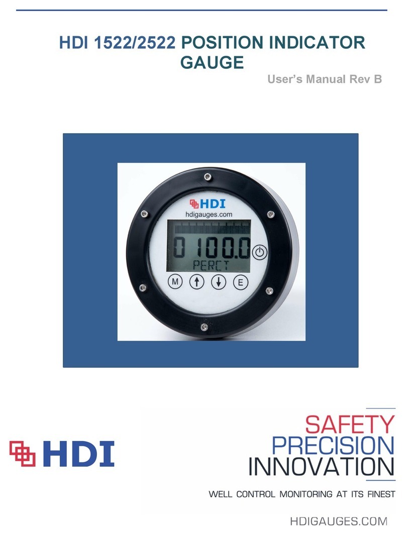
HDI 2200 Position Indicator Gauge
User’s Manual Rev3

HDI 2200 Position Indicator
User’s Manual – 2200, Rev 3 | JAN 2020
2
TABLE OF CONTENTS
SECTION 1 Systems General Information:
1.1 General Information:
1.2 Unpacking and Inspection:
1.3 Precautionary Information:
1.4 Personnel Qualifications:
SECTION 2 System Description:
2.1 System Description General:
2.2 System Components:
2.2.1 Position Indicator:
2.2.2 Position Sensors:
2.2.3 Cables
2.3 System Capacities:
2.3.1 Position Indicators:
2.4 System Options
2.4.1. Remote Display:
2.4.2. 4/20 mA Output:
2.4.3 0-1VDC Output:
SECTION 3 Installation:
3.1 Components Location:
3.1.1 Console and Sensors:
3.1.2 Cables:
3.2 Mounting Hardware
3.3 Potentiometer Assembly & Installation
3.3.1. General Assembly
3.3.2. Display Installation
3.3.3. Cables
3.4 4-20mA Potentiometer Installation
SECTION 4 Theory of Operation:
4.1 Position Systems:
SECTION 5 Calibration:
5.1 Position Systems:
SECTION 6 Corrective Maintenance:
6.1 Position Systems:
6.2 Position Systems Battery Replacement:
6.3 Adjustment Preparation

HDI 2200 Position Indicator
User’s Manual – 2200, Rev 3 | JAN 2020
3
SECTION 7 Preventative Maintenance
7.1 Choke Systems:
SECTION 8 Certification
8.1 Markings
8.2 Reports
SECTION 9 Warranty

HDI 2200 Position Indicator
User’s Manual – 2200, Rev 3 | JAN 2020
4
SECTION 1 Systems General Information:
1.1 General Information:
This manual describes the installation operation and maintenance of the HDI #2200 Position
Indicating System. This manual shall provide the user with information necessary to properly utilize
the Position Indicating System. Included in this manual are all the necessary procedures to install
and maintain this Position Indicating System Instrumentation properly.
1.2 Unpacking and Inspection:
Upon receipt of the equipment, assure all items are accounted for on the packing list. If any items
are missing, immediately inform the freight forwarder. Inspect all items for damage. If any items
are damaged immediately inform the freight forwarder and Houston Digital Instruments, Inc.
1.3 Precautionary Information:
Assure all directions on the packages are followed during unpacking and handling. Please note:
if the return spring is preinstalled on the linear shaft, Do Not compress the spring and let the spring
to freely extend. There is enough force when compressed that the linear shaft can be pulled from
the internal body. If damaged, the linear potentiometer must be replaced. The unit is an oil-filled
sealed unit.
1.4 Personnel Qualifications:
This equipment requires experienced personnel to handle, install and maintain. HDI offers a
technical training school on their premises if the Customer desires.

HDI 2200 Position Indicator
User’s Manual – 2200, Rev 3 | JAN 2020
5
SECTION 2 Systems Description:
2.1 Systems Description:
The HDI 2200 System is an Electronic Position Indicating System. The system consists of three
(3) primary components as detailed in Section 2.2. An electronic potentiometer is housed in a
stainless steel housing based on your specific choke body. The assembly is adjustable inside the
housing to assure the sensor is located properly. The housing(s) are constructed to adapt to a
variety of choke(s): Shaffer/NOV, Cameron, Swaco, Control Flow, Cortec and others as required.
The display is a liquid crystal display (LCD), which includes both a three digit numerical display
(for accuracy) and a bar-graph (101 segments) representation (for trend).The electronic bar graph
display indicates choke position from closed to open, 0 - 100 percent and in 1/8 graduations.
Dependent on choke body, your LCD may be configured to be shown as percent (%) Closed versus
the traditional percent (%) Open.
2.2 System Components:
2.2.1 Position Indicators:
Two (2) Position Indicators with numeric and Bar Graph displays are used for dual applications for
respective Left / Right Choke or Choke / Kill identification; otherwise, a single display system is
used for Single Choke applications.
2.2.2 Position Sensors:
As noted above, HDI has designed several different sensor housings to be compatible to various
choke styles to reduce onsite customization and to simplify installation after removing the existing
pneaumatic sensors. General dimensional drawings or photos are available upon request.
2.2.3 Cables:
All interconnecting cables supplied by HDI or can be adapted to use junction box for open
termination.
2.3 System Capacities:
2.3.1 Position Indicators:
Choke Position Indicators are rated for 0 to 100 percent or in one-eighth graduations and will be
respective of your choke body orientation for Open or Close .
2.4 System Options:
Custom designed systems will include, per the customers' request or customers' specifications,
certain options required to meet offshore area classifications or specific customer requirements.
Each system of this type will be designed to meet specific requirements or classifications and is
therefore unique and as such goes beyond the scope of this publication. Barriers or explosion
proof junction boxes are not required as the system has been certified intrinsically safe by the
Canadian Standards Association (CSA). The following are common examples that may be
encountered or requested by customers. HDI offers the following options at additional cost.

HDI 2200 Position Indicator
User’s Manual – 2200, Rev 3 | JAN 2020
6
2.4.1. Remote Display:
Remote displays may be provided to allow secondary indicators at an alternate location at the
customer’s request.
2.4.2 4/20 mA Output:
HDI offers as an option, a signal current loop providing a 4/20 mA remote output that may be used
for chart recorder inputs and/or datalogging.
2.4.3 0-1VDC Output:
HDI offers as an option, a signal providing a 0-1Vdc remote output that may be used by the
customer for chart recorder inputs and/or datalogging. This is a factory installed option and does
not require calibration.
2.4.4 ATEX Compliance
HDI offers as an option, to have units third party inspection by DNV for ATEX Compliance. This is
done on special requests and lead times may vary dependent on DNV availability and HDI’s current
delivery schedule. Copy of the ATEX Certificate showing the approved classification and marking
is available upon request.

HDI 2200 Position Indicator
User’s Manual – 2200, Rev 3 | JAN 2020
7
SECTION 3 Installation:
3.1 Components Location:
3.1.1 Control Head and Sensors:
The Control Head and Sensors are to be mounted by the Customer at the locations deemed most
suitable for such equipment. The system transducer (POTENTIOMETER) comes from the factory
as a complete assembly and only requires mounting of the transducer housing using standard
practices for such installations.
3.1.2 Cables:
All wire lengths from the Panel to the sensors shall be supplied by the customer. Prefabricated
cables from HDI typically have the 3 Pin Male / 3 Socket Female connectors for quick installation.
3.2 Mounting Hardware:
Sensor integration to the choke bodies will generally use the existing bolts from the pneumatic
sensors once removed, while the HDI sensors will be complete with all necessary hardware or
adaptive stems as required for Swaco Rotary Sensors. Custom fit ups are available as option by
HDI.
3.3 Position Sensor Assembly and Standard Installation:
3.3.1 Assembly General:
The Position Potentiometer and mounting brackets are provided to replace an existing pneumatic
regulator choke position system presently in use.
This assembly is designed to mount in the original choke position enclosure utilizing the existing
hole patterns and mounting hardware. Remove the existing choke position assembly. Install the
new stainless steel housing and potentiometer assembly with mounting brackets with the existing
mounting hardware.
Standard Linear Potentiometer,
Loosen the potentiometer brass mounting brackets to allow for adjustment. With the choke body
in the fully closed position, adjust the cylinder potentiometer assembly to allow 1/8” to 1/4"
compression of the shaft into the potentiometer housing and tighten the bolts on the brass
mounting brackets. Observe the choke bodies and sensor while you Open the Chokes to assure
the potentiometer does not bottom out inside the cylinder housing. Once you confirmed there is
no issues, you may proceed to Calibration, see Section 5.
Rotary potentiometer:
HDI provides an adaptive shaft (for Swaco) that must be threaded into the existing choke shaft via
the adjustment stud. As part of the initial set up for a rotary sensor, the potentiometer is marked
with the active span for proper installation and orientation. Orientation to Clockwise and
counterclock-wise operation is critical to avoid crossing into the dead span of the potentiometer,
which will cause a spike or erratic reading on your LCD. Once you believe you have orientated
the Rotary potentiometer to match Clockwise and Counterclock-wise orientation, gently tighten the
set screw on the brass mounting block to secure the potentiometer assembly from rotating during
operation.

HDI 2200 Position Indicator
User’s Manual – 2200, Rev 3 | JAN 2020
8
3.3.2. Position Display:
The system gauge is designed to be installed in a 7.25” x 4.25” cut-out hole in the panel. Mounting
dimensional drawing is located in the rear of this manual under Appendix. Remove the ¼” elastic
stopnuts from the ¼-20 screws, drop the gauge in the appropriate hole and replace the stopnuts.
As part of our deliverables, HDI provides and rubber gasket that allows the LCD display to be
dropped in from the front of the panel face or can be inserted from the back side based on your
preference and serviceability.
3.3.3. Cables
The system comes complete with wire and connectors made to the customer’s specifications.
Simply route the wire from the transducer to the gauge using standard practices, connect the
cables to the transducer and gauge, and tighten the collars.
3.4 Non Certified 4-20 mA Position Sensor Assembly Installation:
HDI offers our sensor configurations with a Slidewire Potentiometer 4-20mA converter allowing
our clients to directly interface with a Data Acquistion or PLC system. This configuration is
installed in the same manner as previously addressed in this manual. The sensor housing will
have a small junction box mounted to the housing or may be mounted near by per a client’s
request. Depending on your request, the jbox may have open ended cables for direct
termination or interface connectors may be configured for plug and play approach.
The converter is a SEM210X, an ATEX cerfitied component that requires an external resistor
across terminals 3 & 5 (484.5 ohm) which has already been preinstalled and a spare is included
with your shipment so when servicing the unit, you have a spare. As with a 4-20mA signal, the
unit requires 24vdc to complete the current loop. Please note, the SEM210 is calibrated via full
2k resistance travel and is not adjustable. Your PLC system should allow you to set the
respective high side of the SEM210 output to your high side reference and complete the display
span of 0-100%.
Wiring layout is included in the Appendix of this manual. You may skip Section 4 and 5 and
reviewing System Maintenance. *Although SEM210X is a certified ATEX component, the
overall Assembly of the 4-20 mA is not certified.

HDI 2200 Position Indicator
User’s Manual – 2200, Rev 3 | JAN 2020
9
SECTION 4 Theory of Operation:
4.1 Positioning Systems:
The major components of this system consist of the Control Head, Sensor, and interconnect Cable.
The LCD (Control head) has an internal Power Source, a 3.6 potted (replaceable) Battery Pack
that supplies power to the LCD via the power cable. The Control Head then supplies the excitation
to the Sensor. The Sensor is typically a 2 or 5K potentiometer that measures its own extension
and compression. This information is returned to the Control Head in which it then converts the
voltage to digital information which is used to drive the 101 segment Bar Graph display with one-
eighth division Bar Graph. The Position Indicator does not require any warm up period. Turning
the system off when not in use will greatly extend battery life
(Power OFF by pressing the Mode Select Button and then pressing the Power Button.)
The Position Indicator contains these operator initiated functions:
Mode Select Button
Selects calibration and
power on/off Modes.
UP ARROW
100% Calibration Select Button
Allows for calibration at
open position.
DOWN ARROW
0% Calibration Select Button
Allows for calibration at
closed position.
Enter Select Button
Enters Mode and
Calibration Selections
Power ON/OFF
Power on/off switch.
.
Power ON: Press Power button once (Unit performs self-test, all display segments turn on)
Power OFF: Press MODE button once (the RUN indicator should TURN OFF) then press the
POWER button with-in .5 sec. NOTE: (if the RUN indicator does not
TURN OFF, press the MODE button again)

HDI 2200 Position Indicator
User’s Manual – 2200, Rev 3 | JAN 2020
10
SECTION 5 CALIBRATION:
5.1 Position System:
THIS DEVICE IS CALIBRATED FROM THE POSITION INDICATOR (Display Panel)
(SEE Section 4)
5.1.1 Setting Closed Position Level
1. Once the installation is complete the choke should be closed completely.
2. Apply power to device by pressing the POWER button.
3. Position Indicator will perform self test for approximately 5 seconds during which time
all LCD displays will be active.
4. After self test, the display will be in the run/active mode. ( RUN indicator will appear at
the lower left side of the LCD display)
5. With Choke completely CLOSED, press the MODE button. (RUN indicator will turn
OFF)
6. Press Down button within 2 secs. (Now in calibration mode)
7. The down arrow and a four digit number will appear at the top of the LCD display.
8. Press the Enter button. (Accepts the low / closed set point position, unit returns to RUN
mode)
9. The closed position level is now set, and the three digit display should read 000.0
5.1.2 Setting Open Position Level
1. Open the Choke completely.
2. With Choke completely open press MODE button. (RUN indicator will turn OFF)
3. Press UP button within 2 secs. (Now in calibration mode)
4. the up arrow and a four digit number will appear at the top of the LCD display.
5. Press the Enter button. (Accepts the low / closed set point position, unit returns to RUN
mode)
6. The closed position level is now set, and the three digit display should read 100.0
7. Unit is now fully calibrated.

HDI 2200 Position Indicator
User’s Manual – 2200, Rev 3 | JAN 2020
11
SECTION 6 MAINTENANCE:
6.1 Position System
The HDI 2200 is a digital electronic gauge designed specifically for Oilfield applications. The
system is easily calibrated while at Open and Close respective position and can be completed
within minutes if Minor Adjustments are required. Generally, this system should only require
calibration every 2 years when the power pack is replaced or if there are any change in system
wiring or if a repair is completed. One (1) to two (2) hours per gauge should be allocated if a
potentiometer needs to be replaced allowing the unit to be removed from the choke body,
repaired and then calibrated to the LCD.
6.2 Position Systems Battery Replacement:
Remove the Canon Connector from the back side of the case. Remove the four (4) 1/4"-20 hex
screws, nuts and washers and remove the unit from the panel. Remove the 10 8x32 flat head
phillips screws from the front of the unit. Remove the front plate, trim ring plexiglass and gasket.
Be careful not to damage the gasket. Lay the gauge to the side and assure it does not get
damaged. The battery is secured by velcro to the case. Pull apart the connector that connects
the battery to the display. A large screwdriver may be used by carefully placing it under the battery
to pry it out of the case. Insert the new battery in the case to the velcro. Reconnect the connectors.
It is suggested that you replace the desiccant pack, corrosion inhibitor and humidity indicator at
this time. Reassemble the display which has the HDI 013 processor board assembly as one piece.
If possible, it is suggested that you Test the System to ensure everything is working before closing
up the gauge. You may connect the connector to the case and have the choke bodies functioned
to calibrate the unit per Section V. If the system operates properly, reassemble and remounte in
the reverse order. Connect the canon connector to the rear of the case prior to securing the LCD
to your panel. Check Calibration as a precaution. Note: the Power pack is covered under a 1
year warranty from date of shipment and will generally last you 18-24 months. When not in use,
it is suggested to power off the unit to extend battery life.
6.3 Tools Required for Calibration and Service:
THIS STEP IS NOT NECESSARY WHEN MAKING MINOR ADJUSTMENTS TO A
PREVIOUSLY CALIBRATED SYSTEM
1. Screwdriver, Phillips.
2. Screwdriver, Flat Blade .
3. Nutdriver, 3/8".
4. Nutdriver, 7/16".
Note: All required tools may be purchased from HDI or your local tools shop.

HDI 2200 Position Indicator
User’s Manual – 2200, Rev 3 | JAN 2020
12
SECTION 7 Preventative Maintenance:
7.1 Position Systems:
This system does not require any user maintenance for day to day operation. The battery pack
will need to be replaced on average every two (2) years.
It is suggested for our linear potentiometer systems that you perform a visual inspection from time
to time, perhaps every 6 months to ensure the stem has not been bent. The sensor box when
mounted has some play in the mounting pattern allowing you to align the unit to avoid putting any
bind on the stem while in operation.
You should also periodically check the cables for any visual damage or cuts that will allow water
or moisture into the cable causing interference and erroneous results.
Note: The system calibration should be checked after battery replacement.

HDI 2200 Position Indicator
User’s Manual – 2200, Rev 3 | JAN 2020
13
SECTION 8 Certification:
8.1 Certification Markings:
Gauge Head Sensor
ATEX Certification Markings:
Gauge Head Sensor
Note: In the event one of the components (gauge or sensor) fails, you can order the replacement
for a quick drop in replacement. When ordering, be sure to provide the applicable serial # or
certification requirements to ensure the replacement is acceptable.

HDI 2200 Position Indicator
User’s Manual – 2200, Rev 3 | JAN 2020
14
8.2 Certification Reports:
CSA Report

HDI 2200 Position Indicator
User’s Manual – 2200, Rev 3 | JAN 2020
15
ATEX Report:

HDI 2200 Position Indicator
User’s Manual – 2200, Rev 3 | JAN 2020
16
SECTION 9 – Warranty
HDI Instruments, LLC. (HDI) warrants this product for a period of one year from the date of shipment.
HDI’s manufactured products to the extent that HDI will replace those parts having defects in material
or workmanship when used for the purpose or specification HDI recommends for Normal Oilfield
Usage. For the purpose of this Warranty, Normal Oilfield Usage shall be defined as normal, oilfield
monitoring applications.
HDI shall not honor the Warranty if any evidence of tampering, misuse or intrusion is indicated except
by an HDI authorized technician or agent.
HDI will replace or repair, as it deems necessary, any products covered by this warranty, after HDI's
examination discloses to its satisfaction, that in fact the products are defective and an adjustment is
required. If an adjustment is required, the amount of the adjustment is the net sales price of the
defective product. No allowances shall be made for labor or expenses of repairing defective products
or damage resulting from same. All products accepted under the provisions of this warranty shall be
shipped prepaid to HDI and returned to the customer prepaid by HDI. This is to include all applicable
custom clearance fees, etc. for inbound international shipments. All products not accepted under the
provisions of this warranty shall be shipped prepaid to HDI and returned freight collect.
HDI shall not be responsible for repair or replacement of products, resulting from improper handling,
storage, installation, misuse, negligence, or use in a manner contrary to the recommendations of HDI.
HDI warrants only the products that it sells of Other Manufacturers to the extent of their warranties. All
warranty claims shall be made in writing to the nearest HDI office or authorized factory representative.
HDI makes no other warranty of any kind, expressed or implied, and all implied warranties of
merchantability or fitness for a particular purpose which exceed HDI's afore-stated obligation are hereby
disclaimed by HDI and excluded from this warranty.
This Warranty is non transferable and HDI shall not be liable for any damage, injury, loss to property
or persons resulting from the use of any HDI's products or equipment whether such damage, injury or
loss results from, or is caused by: manner of use, defects in materials or workmanship or otherwise.

HDI 2200 Position Indicator
User’s Manual – 2200, Rev 3 | JAN 2020
17

HDI 2200 Position Indicator
User’s Manual – 2200, Rev 3 | JAN 2020
18
APPENDIX A
WIRING INFORMATION:
Input from Sensor:
See listing under HDI 013 PCB in the table below:
Sensor Wiring:
Linear Potentiometer
Device Markings
Connector
HDI 013 PCB
Color Code
1
A
P
BLACK
2
B
S
WHITE
3
C
G
GREEN
Rotary Potentiometer
w/ stem face you
Connector
HDI 013 PCB
Color Code
Left
A
P
BLACK
Middle
B
S
WHITE
Right
C
G
GREEN
4-20mA Output (from LCD):
Connector
A
B
C
D
E
Function
Code
4
-
20 +
4
-
20
-
Not Used
Not Used
GRND
Color
Black
White
Red
Green
Shield
For custom specific 4-20mA Transmitter applications, see below drawing for (2) possible
options:

HDI 2200 Position Indicator
User’s Manual – 2200, Rev 3 | JAN 2020
19

HDI 2200 Position Indicator
User’s Manual – 2200, Rev 3 | JAN 2020
20
Client Maintenance Notes
Table of contents
Other HDI Measuring Instrument manuals
Popular Measuring Instrument manuals by other brands
DAKOTA ULTRASONICS
DAKOTA ULTRASONICS PZX-7 Operation manual
Nellcor
Nellcor OxiMax N-550 Operator's manual

TESTO
TESTO 512 instruction manual

Tonghui Electronics
Tonghui Electronics TH1991 Operation manual
Endress+Hauser
Endress+Hauser Liquiline System CA80HA operating instructions

NeurOptics
NeurOptics NPi-300 quick start guide

