Eagle Eye Power Solutions BQMS User manual

1
Eagle Eye Power Solutions, LLC
BQMS
Battery Monitoring System
Installation Manual 052319
www.eepowersolutions.com | Tel: 1-877-805-3377 | Fax: 1-414-962-3660 | [email protected]

2
Table of Contents
1. Introduction ...................................................................................................... 4
1.1 Safety Information ........................................................................................................... 4
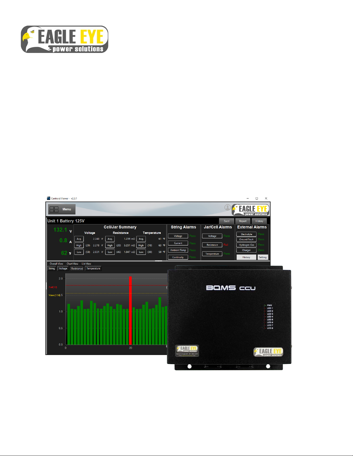
2. Product Overview ............................................................................................ 5
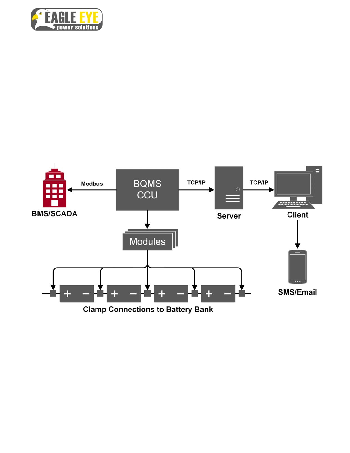
2.1 System Composition ....................................................................................................... 6
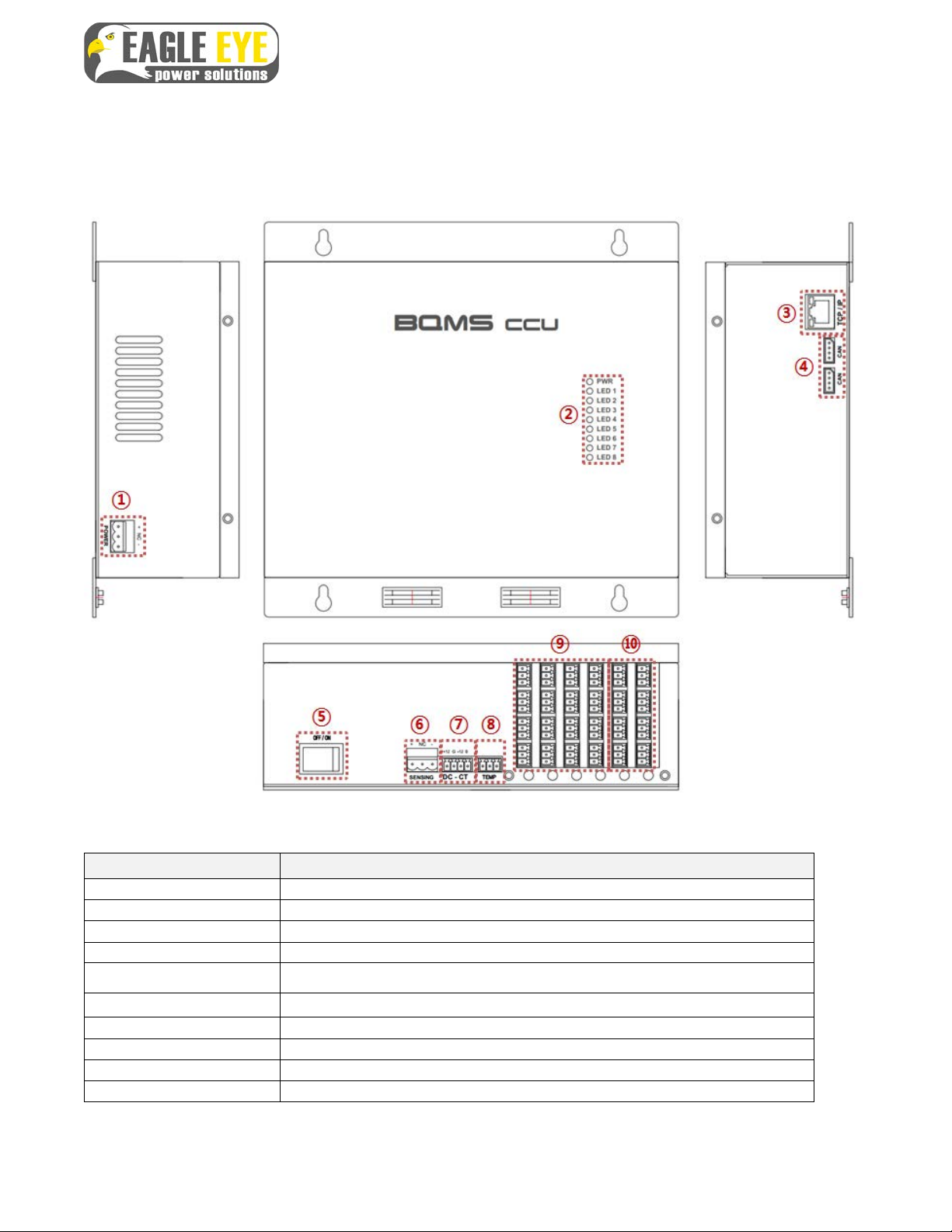
2.2 Communication Control Module (CCU) ......................................................................... 7
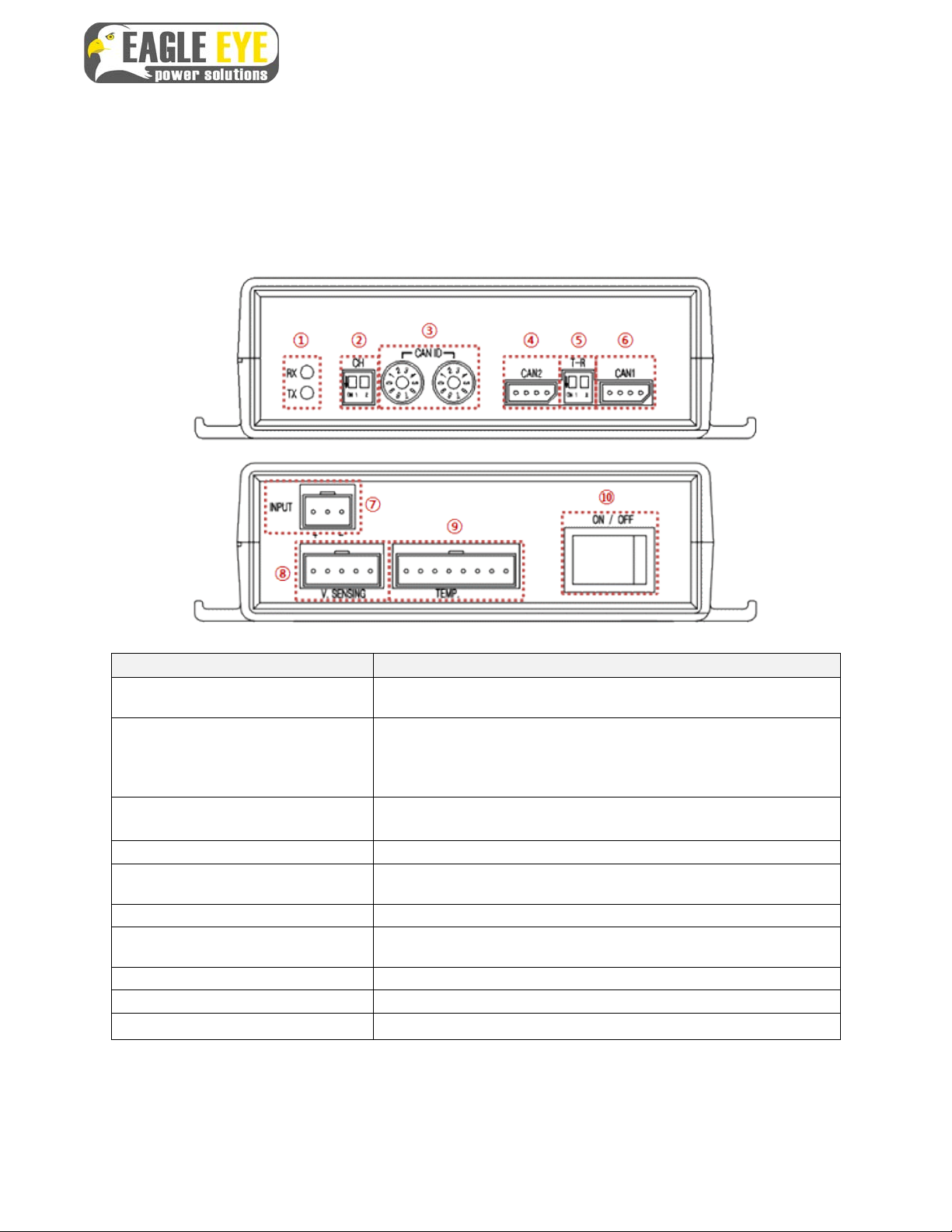
2.3 Measuring Unit Module ................................................................................................... 8
2.4 Technical Specifications ................................................................................................. 9
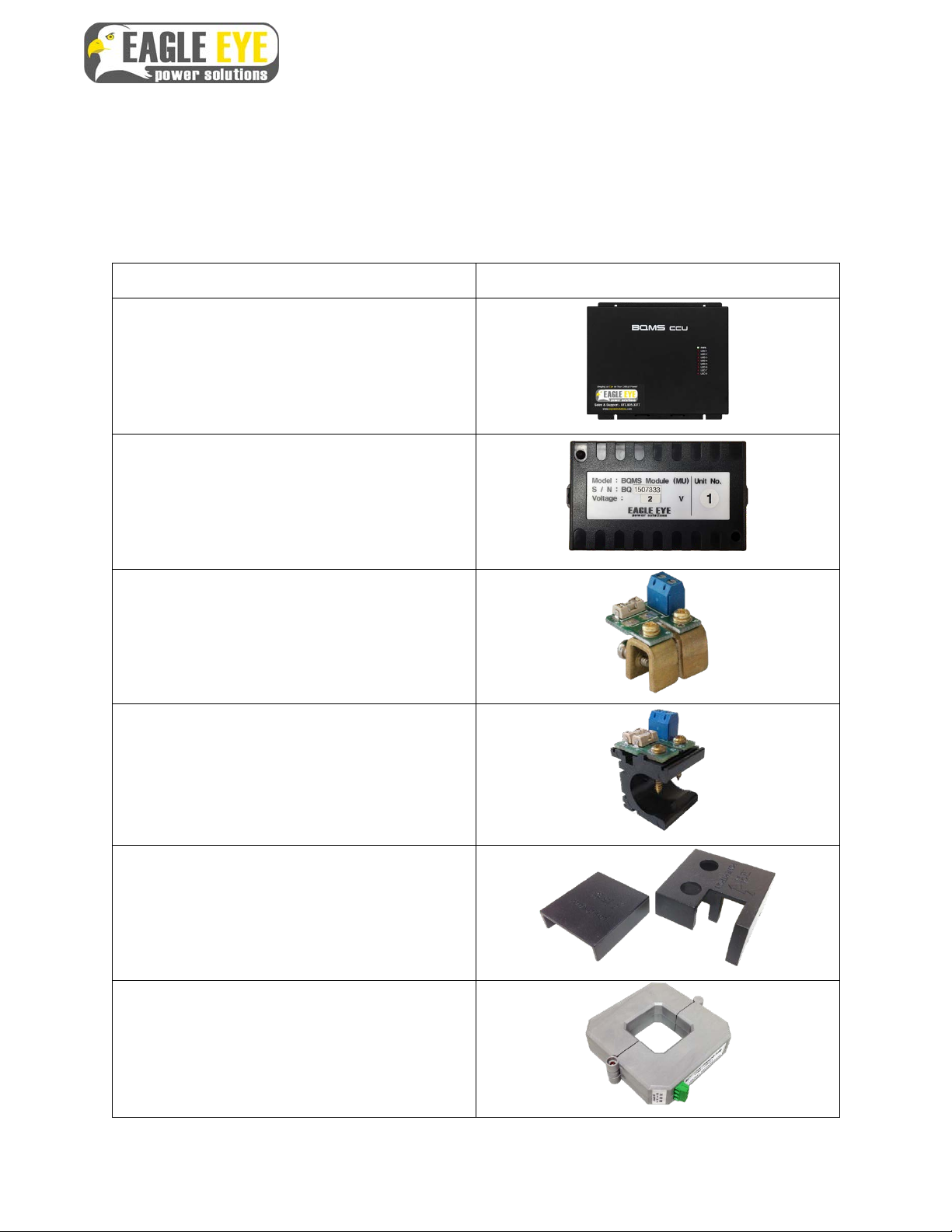
3. Parts List ........................................................................................................ 10
4. Installation Tools ........................................................................................... 12
4.1 Standard Installation Tools .......................................................................................... 12
4.2 Recommended Tools .................................................................................................... 13
5. Hardware Installation .................................................................................... 14
5.1 Overview of Workflow ................................................................................................... 14
5.2 Mount CCU or Cabinet Enclosure ................................................................................ 15
5.3 Check & Mount Modules ............................................................................................... 16
5.4 Clamp Installation .......................................................................................................... 18
5.4.1 Prepare for Connection ............................................................................................. 18
5.4.2 Connection of Clamps (C-Type) ................................................................................ 19
5.4.4 Connection of Clamps (O-Type) ............................................................................... 20
5.5 Sensing Cable Connections ......................................................................................... 21
5.5.1 Sensing Cable Overview ........................................................................................... 21
5.5.2 Cable Connection to 2V Cell/unit: ............................................................................. 22
5.5.3 Cable Connection to 4V Unit: .................................................................................... 23
5.5.4 Cable Connection to Multiple 12V Units: ................................................................... 24
5.5.5 Cable Connection to Single 12V Unit: ....................................................................... 25
5.5.6 Preliminary Cable Routing ........................................................................................ 26
5.5.7 Install Wire duct (Optional) ........................................................................................ 27

3
BQMS Installation Manual
052319
5.5.8 Route Sensing Cables to Clamp Connections .......................................................... 27
5.5.9 Terminate Sensing Wires to Clamps ......................................................................... 28
5.5.10 Connect & Adhere Temperature Sensors ............................................................... 29
5.6 CAN Cable Connection ................................................................................................. 31
5.7 Input Voltage and System Voltage Cable Connection ............................................... 33
5.7.1 Voltage Connections Directly to CCU ....................................................................... 33
5.7.2 Voltage Connection to Enclosure Terminal Block ..................................................... 34
5.7.3 Connect Total Voltage & DC Power Cables to Battery System ................................ 35
5.8 Install DC-CT Clamp ...................................................................................................... 37
5.8.1 Connect CT Cable Harness to BQMS CCU .............................................................. 37
5.8.2 Connect CT Cable to CT ........................................................................................... 38
5.8.3 Attach CT to Battery System ..................................................................................... 38
5.9 Ambient Temperature Connection ............................................................................... 39
5.10 Verify Connections ...................................................................................................... 40
5.10.1 Check Voltage & Current Sensing Connections ..................................................... 40
5.11 Connect Sensing Cables to Modules ........................................................................ 42
5.12 Dry Contact Setup ....................................................................................................... 43
5.12.1 Dry Contact Overview ............................................................................................. 43
5.12.2 Dry Contact Overview ............................................................................................. 44
5.13 Dry Contact LEDs ........................................................................................................ 45
6.0 Initial Power Up ............................................................................................ 46
7.0 Network Communication Setup ................................................................. 47
7.1 Configure MPU IP Address ........................................................................................... 47
7.2 Connect BQMS to Network ........................................................................................... 48
8. Resistance Compensation ............................................................................ 49
8.1 Determine Compensation Values ................................................................................ 49
8.2 Performing Cell Compensation with BQMS Monitor .................................................. 49

4
BQMS Installation Manual
052319
1. Introduction
This manual provides guided steps on how to install the Eagle Eye BQMS Battery Monitoring System
safely and effectively. Please read this manual carefully to fully understand the functionality of the
BQMS. The BQMS is also part of the EE-NERC-BMS solution and should be used in conjunction with
support literature for associated products such as the ELM-Series and GFM-Series.
1.1 Safety Information
Operation methods and safety measures described in this manual are only applicable to the defined
purpose and functionality of the BQMS. If the BQMS is used in a way not specified in this manual, the
safety of the equipment, personnel, and property cannot be assured.
• Please read this manual carefully to avoid accidental injury or misuse of product.
• Only qualified personnel with proper tools and equipment should work on batteries.
• To avoid damage and injury due to the short circuiting of battery terminals, wrap insulating tape
around all metallic parts.
• Do not wear metallic items such as jewelry, watches, & rings. Wear insulated gloves and
goggles when working around batteries.
• Ensure an installation supervisor is on hand when connecting the BQMS and battery post to
avoid fire or personal injury.
• Make sure all personnel are fully aware of safety guidelines.

5
BQMS Installation Manual
052319
2. Product Overview
The BQMS is designed to monitor and analyze the state of health of stationary backup power systems
by measuring and recording: string voltage, string current, cell/unit voltage, internal/connection
resistance, cell/unit temperature, & ambient temperature.
All BQMS solutions come complete with battery management software which allows all battery systems
to be monitored 24 hours a day, 365 days a year via remote computer(s). This software offers
comprehensive battery diagnosis and reporting capabilities to ensure the integrity of your critical
backup power system.
Alternatively, systems can be configured for Modbus or DNP3 communication for integration to a third-
party building management system or SCADA (supervisory control and data acquisition).
BQMS Installation to 125V Battery Bank

6
BQMS Installation Manual
052319
2.1 System Composition
The BQMS system composition is as follows:
1. A single Communication Control Unit (CCU) connects to a single battery bank.
2. Each bank has Modules which connect from the CCU to the battery cells in daisy chain.
3. The CCU(s) communicate with the Server PC via Ethernet over a company / private network.
4. The CCU can also alarm out via up to (5) native Form C contacts and (8) additional external
contacts.
5. Client software installations can display measurement data from the Server PC.

7
BQMS Installation Manual
052319
2.2 Communication Control Module (CCU)
The CCU receives battery data and communicates with the Server. It does not store battery data, all
measurement data is stored on the server.
Item
Description
① POWER
Power input termination
② LED
Power LED and alarm LED
③ TCP/IP
Ethernet port
④ CAN PORT
CAN communication port (connects with Modules)
⑤ ON/OFF
Power (ON/OFF switch)
⑥ SENSING
Total voltage termination
⑦ DC-CT
Total current (DC-CT) termination
⑧ TEMP.
Ambient temperature termination
⑨ DRY CONTACT
Dry contact input / output ports
⑩ INPUT
Dry contact input ports

8
BQMS Installation Manual
052319
2.3 Measuring Unit Module
The Measuring Unit (Module) relays connection between the CCU and battery cells. Each module is
powered by DC from the connected battery. There are different modules for cell/unit voltages in the
range of: 2V, 4V, & 12V. Modules are numbered and set at the factory prior to shipment.
Item
Description
① Communication LED
– RX: Data receive indicator LED
– TX: Data send indicator LED
② CH: Set Cell Quantity
Measured by Module
– OFF/OFF: (1) cell measured
– OFF/ON: (2) cells measured
– ON/OFF: (3) cells measured
– ON/ON: (4) cells measured
③ CAN ID
CAN ID dial, sets can ID number. (Ex. Module “14” would
have a can ID of dial 1 = 1 and dial 2 = 4.
④ CAN Communication Port
CAN communication port 1
⑤ Terminator Resistance
CAN communication terminator resistance, set to ‘ON’ for
last module only
⑥ CAN Communication Port
CAN communication port 2
⑦ INPUT
Current connection for Is Cable Harness (resistance
measurement)
⑧ V.SENSING
Voltage connection for VS Cable Harness
⑨ TEMP.
Temperature connections for Temp. Cable Harness
⑩ ON/OFF
Power switch

9
BQMS Installation Manual
052319
2.4 Technical Specifications
Applications
Flooded, Sealed, & NiCad* battery types
Cell/Unit Voltage Range
2V, 4V, 6V, or 12V nominal
Discharge / Charge Current
±4,000A
DC Voltage
±576 VDC
Accuracy
DC Voltage / Current: ±0.5% / ±2%
Cell Voltage: ±0.5%
Internal Resistance: ±2%
Temperature: ±2%
Resolution
DC Voltage / Current: 0.1V / 0.1A
Cell Voltage: 0.001V
Internal Resistance: 0.001mΩ
Temperature: 0.1°C
Test Speed
30 seconds per bank
Test Load
Less than 2A AC per cell
Display
LED indicator lights for alarms
Alarm Relays
Form C output contacts
Dry Contact Ratings
Nominal: 2A at 60V AC/DC
Max: 0.5A at 250VAC / 0.27A at 220VDC
Measuring Interval
Adjustable from 10 min to 24 hours
Data Transfer
TCP/IP, Modbus, DNP3
Operating Environment
Temperature: 0 – 66°C (32 – 150°F)
Relative Humidity: Under 80% RH
AC Power Requirements
110 – 220 VAC, 50/60Hz
CCU Power Requirements
AC: 85 – 264 VAC, 3.75W
DC 48V: 36 – 72 VDC, 15W
DC 120/240V: 120 – 370 VDC, 3.75W
Module Power Requirements
2V: 4.5 – 18 VDC
4V: 9 – 18 VDC
12V: 18 – 36 VDC
Input Current Draw
Module: Under 100mA
Dimensions L x W x D
CCU: 210 x 76 x 197 mm (8.25 x 3 x 7.75 in)
Module: 114 x 70 x 39 mm (4.5 x 2.75 x 1.5 in)
*NiCad cells must be measured in pairs of 2.4V nominal or higher.

10
BQMS Installation Manual
052319
3. Parts List
The following parts come standard with each BQMS package. Refer to the included packing slip for
exact quantities of each part.
Part Name & Purpose
Picture
CCU (Communication Control Unit)
Main processing unit for BQMS system.
Measures total voltage, current, & ambient
temperature
Measurement Module
Measures cell/unit voltage, resistance, &
temperature
C-Type Clamp
Clamp used for connection between batteries
with bus bar inter-cell connections
O-Type Clamp
Clamp used for connection between batteries
with cable inter-cell connections
Clamp Covers: C-Type / O-Type
Placed over clamp PCB
Hall Effect CT
Measures charge / discharge current

11
BQMS Installation Manual
052319
AC Power Cable
Power cable for systems utilizing AC power
Total Voltage / DC Power Fuses
Fused lines between the Total Voltage & DC
Power Cables
String VDC and DC Power Cables
Positive and negative cable sets for string
voltage measurement and DC voltage input
CCU-Module CAN Cable (4-pin)
Data communication between CCU and
Modules.
CCU-CCU CAN Cable (4-pin)
Data communication between Modules.
CT Cable Harness (3P)
For connection between CT & BQMS CCU
Temperature Cable Harness (8-pin)
Measures temperature of battery posts

12
BQMS Installation Manual
052319
Voltage Sensing Cable Harness (5-pin)
Measures DC voltage (Vs)
Current Sensing Cable Harness (3-pin)
Measures resistance (Is)
Provides DC power to Module
4. Installation Tools
4.1 Standard Installation Tools
Tool Name & Purpose
Picture
Multi-meter
Verification of connection voltage &
resistance
#1 Phillips Insulated Screwdriver
Tightening of O-Type/C-Type clamp screws
to bus bar
2/16” (2-3 mm) Precision Screwdriver
Termination of battery sensing cables to
clamp connections
Wire Cutter
Adjustment of cable length

13
BQMS Installation Manual
052319
Mounting Hardware & Tools
Depending on wall surface, various drills,
sockets, and other tools may be required to
mount the BQMS
Wire Stripper
Adjustment of cable length, 12 to 22AWG
required
Shop Snips
Adjustment of duct length, cable length
Cable Ties
Cable management
Wire Tray (Optional)
Cable routing and management
4.2 Recommended Tools
Tool Name & Purpose
Picture
IBEX Battery Tester
Verification of BQMS measurement readings,
cell compensation

14
BQMS Installation Manual
052319
5. Hardware Installation
This section will provide the correct workflow for installing the BQMS Battery Monitoring System and all
of its components.
All necessary cables and clamps are provided at correct quantities and lengths based on information
provided from the Site Survey. Please be sure to have all the necessary tools and parts listed in
Section 3 and 4.
5.1 Overview of Workflow
The following is an overview of the complete workflow of what needs to be done on-site for the BQMS
Installation.
1. Mount BQMS CCU
2. Install Clamps to battery connections
3. Install Sensing Cables
4. Install Temperature Sensors
5. Check & mount Modules
6. Connect Total Voltage Cable and power connections
7. Install CT
8. Verify all connections
9. Power on Modules and CCU
10. Configure BQMS CCU IP address
11. Check measured parameters and resistance compensation
12. Connect BQMS to network
NOTE: This guide should be used as an outline for installation, however it does not cover
every aspect of installation step-by-step. It is recommended that experienced personnel
familiar with electrical work and battery-room environments perform this installation. If a
section of this guide is unclear, please contact Eagle Eye Power Solutions directly for further
support.

15
BQMS Installation Manual
052319
5.2 Mount CCU or Cabinet Enclosure
Parts:
CCU, mounting hardware (not included)
Tools:
Mounting tools
1. The CCU/Cabinet should be mounted in the same location indicated during the Site Survey
process. Provided cabling is cut to length based on this location.
2. Observe areas around the CCU/Cabinet to ensure there is adequate room to connect the
various cables into the unit.
CCU Installed Directly to Wall CCU Installed in Cabinet Enclosure

16
BQMS Installation Manual
052319
5.3 Check & Mount Modules
Parts:
Modules, mounting hardware (not included)
Tools:
2/16” (2-3 mm) flathead screwdriver, mounting tools
The Modules are wired to the clamps installed between each cell/unit and measure the battery voltage,
internal resistance, and temperature. The measured data is relayed back to the CCU via the CAN
Cable. There are a number of settings on the Modules which need to be programmed correctly in order
for the system to operate correctly. Each Module has a colored dot sticker on it, this refers to its current
draw and is grouped at the factory.
1. Prior to mounting the modules, the CAN ID should be checked for accuracy against the Unit No.
printed on the face of the Module.
a. The face of each Module has a Unit No.
b. Check that the CAN ID matches the Unit No.
c. Check the CH Switches are set correctly (refer to sections 5.5.2 to 5.5.5)
d. Check that the T-R Switches are set correctly, they should be ‘OFF/OFF’ for all Modules
except the last Module which should be set to ‘ON/ON’.
2. The Modules should be mounted roughly in the middle of the cells it will be monitoring. For
example, if monitoring (4) 2V cells per Module, mount the Module on the rack between cells 2 &
3.
3. Each module has tabs on each end allowing the unit to be mounted on the battery rack or strut
as pictured below. If mounting to strut, use 10/32 bolts.
NOTE: Modules are programmed correctly at the factory, however it is still recommended to
verify settings prior to mounting.

17
BQMS Installation Manual
052319
Modules Mounted on Battery Rack
TIP: Cables will need to be connected to the Modules in the coming steps. If the Module’s
mounted location makes the connector ports difficult to access, consider setting the Module
in the general location it will be mounted and finish mounting after all cables are connected.

18
BQMS Installation Manual
052319
5.4 Clamp Installation
Parts:
C-Type/O-Type clamps, Clamp Covers (optional)
Tools:
Phillips screwdriver
The BQMS includes clamps for installation to the inter-cell connections of the battery system. There are
two clamp types:
C-Clamp: Screws on to the battery bus bars or terminal plate.
O-Type: Penetrates into the cable connections via (2) screws
The purpose of the clamps to provide a non-intrusive, fused connection to the battery system for
measurement. The fuses are housed on a small PCB on each clamp. The placement of the clamps is
based on the PCB type. There are two types of PCBs:
Voltage (referred to as “Vs”): Houses a 1A fuse only for voltage measurement only.
Current (referred to as “Is”): Houses a 1A fuse for voltage measurement in addition to a 3A fuse for
current.
Clamp Type
PCB Type
C-Type
for Bus bar
O-Type
for Cable
Voltage:
(Vs)
(1 fuse)
Current:
(Is)
(2 fuse)
5.4.1 Prepare for Connection
1. Organize clamps based on type and verify all clamps are present.
2. Reference the provided Cable Map to determine where each clamp is placed on the system.

19
BQMS Installation Manual
052319
5.4.2 Connection of Clamps (C-Type)
1. Connect clamps according to the provided Cable Map.
2. Determine how the clamp will be placed. Generally, the wire terminations should be facing
the direction the sensing cable(s) will be ran from.
3. Place the clamp in the center of the bus bar and tighten down using the provided screws.
4. If the bus bar has a cover, cut out an area so the cover sits snugly against the clamp.
5. Attach additional clamps, keep the direction and placement of all clamps consistent.
6. If the batteries to do not have covers, it is recommended to place the provided covers on
each clamp.
Cover Cut around C-Type Clamp C-Type Clamp Mounted with no Cover
C-Type Clamp Mounted with Provided Cove

20
BQMS Installation Manual
052319
5.4.4 Connection of Clamps (O-Type)
1. Connect clamps according to the provided connection diagram.
2. Determine how the clamp will be placed. Generally, the wire terminations should be facing
the direction the sensing cable(s) will come from.
3. Place the clamp over the center of the cable and tighten the screws into the cable
NOTE: If the cable is too large for the clamp it can cut down to accommodate the size.
4. Attach additional clamps, keep the direction and placement of all clamps consistent.
O-Type Clamp Connections
Breaking Points
Table of contents
Other Eagle Eye Power Solutions Measuring Instrument manuals
Popular Measuring Instrument manuals by other brands

Ametek
Ametek AMEVision 3050-TE user manual

Hanna Instruments
Hanna Instruments HI 96821 instruction manual

Haug
Haug Static Control Digital Operating instruction

Vision & Control
Vision & Control TO30/4.3-100-V-B Instructions for use

ATEQ
ATEQ VT37 user guide

Johnson Controls
Johnson Controls AD-1272 Technical bulletin