HDT NTT 240 User manual

NTT 240/460
Compact digital drive for AC and DC, rotary, linear and tubular, brushless,
asynchronous, and DC permanent magnets motors at 230Vac and 400Vac
with resolver or incremental/absolute encoder. Operation mode via Ether-
cat CoE, Profinet RT, Profibus DPv0, Canopen®, ModbusRTU and I/O.
INSTALLATION AND USER GUIDE

2Installation and user guide
Rev: 4.0
NTT 240/460
Manual or NTT 240/460 drive changes
Manual Changes Description
Manual, Drive and Caliper
Vers. FW
Drive
Vers. SW
Caliper
HW Vers.
Drive
10/01/2019 Rev: 4.0 • First release for Caliper software suitable for NTT 240/460 drives. • 4.00 • 4.04
• 4.05
0 - 0
• V/Hz control for asynchronous motors. • 4.01 • 4.07
• 4.08
• Ethernet connector now available (not managed at the moment).
• J7 connector at pin 16: +24V supply for frequency output now available on
request.
• 4.02 • 4.08
• 4.09
• 4.10
• 4.11
0-1
• External encoder loop management now added. • 4.05 • 4.12
• 4.13
• Position software limit now added for Canopen operation mode. • 4.06
• Pressure control topology now added.
• Automatic convertion for IVT le from previous DGM series now added.
• 4.07 • 4.15
• Current oset for motor brake management now added. • 4.08
• Current limit management available with or without decimal.
• Display H6 menu moved in S9.
• 4.09
• 4.10
• 4.11
• 4.16
!
It’s recommended to always verify drive rmware version in order to connect it to the related and correct
Caliper version.

3
NTT 240/460
Installation and user guide
Rev: 4.0
Thanks for choosing this H.D.T. product.
www.hdtlovato.com
Read carefully this manual before using this product.
For continuous improvement, H.D.T. reserves the right to
change features and specications to manual and product
without notice for the customer.
Any parts of this manual can not be reproduced in any
way or transmitted without a write permission from the
manufacturer.
Details of images, contained here in, may be dierent from
real product.
All rights reserved.
Doc. NTT 240/460
Rev. N° 4.0
Date 10/01/2019
All trademarks belong to their respective owners.

4Installation and user guide
Rev: 4.0
NTT 240/460
Summary
Ch. 1 Safety Informations 7
1.01 Danger 7
1.02 Attention 8
1.03 Notes 8
1.04 Directives, marks and industrial standards 8
Ch. 2 Introduction 9
2.01 Description 9
2.02 Delivery ispection 9
2.03 Drive sizes and option conguration 10
2.04 NTT 240 drive features 12
2.05 NTT 460 drive features 13
2.06 Technical data 15
Ch. 3 Installation 19
3.01 Mechanical installation 19
3.02 Dimensions and side view 20
Ch. 4 Supply and quick start 23
4.01 Standard wiring for quick start 23
4.02 Fuses 24
4.03 External braking resistor 24
4.04 EMC Filter 24
4.05 External DC link power supply 25
4.06 DC bus reforming 25
Ch. 5 Wiring and connections 26
5.01 General description 26
5.02 J1 connector: motor power connection 28
5.03 J2 connector: drive power supply and braking resistor 30
5.04 J3 connector: EC and PN option conguration 32
5.05 J3 connector: CM option conguration 33
5.06 J3 connector: PB option conguration 34
5.07 J4 connector: drive settings 35
5.07.1 Using USB 2.0 HUB 35
5.08 J5 connector: Feedback 1 36
5.08.1 Wiring a H.D.T. motor with encoder feedback 38
5.09 J6 connector: Feedback 2 40
5.09.1 Wiring a H.D.T. motor with resolver feedback 41

5
NTT 240/460
Installation and user guide
Rev: 4.0
5.10 J7-8-9 connectors: Frequency, digital and analog I/O 42
5.10.1 J7 connector: frequency I/O 42
5.10.2 J8 connector: digital I/O 43
5.10.3 J9 connector: analog I/O 44
5.10.4 Cable per J7-8-9 45
5.11 J10 connector: RS485 46
5.12 J11 connector: logic supply and S.T.O. safety function 46
5.13 J12 connector: Ethernet 47
Ch. 6 Operation mode 48
6.01 Introducing Caliper 49
6.02 Caliper Data Monitor 51
6.03 Caliper Menu 52
6.03.1 Menu: ‘FIELD BUS’item 53
6.03.2 Menu: ‘MOTOR DATA’item and ‘FEEDBACK’ sub-menu 55
6.03.3 Menu: ‘ADVANCED SETUP’ item 61
6.03.4 Menu: ‘Control Set’ ‘Modbus’ ‘CanOpen’ ‘Ethercat’ ‘Pronet’items 62
6.04 Emergency stop functions 71
6.04.1 FAULT REACTION function 71
6.04.2 HALT function 72
6.04.3 Safe Torque O safety stop function 72
6.05 Factors 73
6.05.1 Factor calculation procedure 73
6.05.2 Custom Application 74
6.05.3 Custom Label 75
6.06 Display and keyboard 76
6.06.1 Keybord access parameters 77
6.07 Motor autophasing 82
6.08 Digital I/O 83
6.08.1 Digital I/O functions 85
6.09 Drive references 87
6.09.1 Main reference 87
6.09.2 Auxiliary references 88
6.10 Speed ramps 89
6.11 Motor brake 90
6.12 Braking resistor 92
6.13 Motor cogging torque compensation 93
6.14 Scope function 94
6.14.1 Scope: ‘CHANNEL SETTING’ 95
6.14.2 Scope: ‘PID SETTING’ and‘WAVE GENERATOR’ 96
6.14.3 Scope: ‘TEST’ 96
6.14.4 Scope: ‘TRIGGER’ 97
6.15 Control topologies 98
6.15.1 Torque control 100
6.15.2 Sensored speed control 101
6.15.3 Sensorless speed control 102
6.15.4 Position control: electronic gearbox mode 103
6.15.5 Position control: positioner mode 104
6.15.6 Position control: electronic cam mode 105
6.15.7 Pressure control 106
6.16 Closed loop regulation tuning 107
6.16.1 Current loop tuning 107
6.16.2 Speed loop tuning 108
6.16.3 Position observer tuning 110

6Installation and user guide
Rev: 4.0
NTT 240/460
6.17 Sensorless loop tuning 111
6.17.1 Setting speed/current loop and motor parameters 111
6.17.2 Setting sensorless parameters 112
6.17.3 Sensorless loop tuning 113
Ch. 7 S.T.O. safety circuit 116
Ch. 8 Drive status and diagnostics 120
8.01 Drive status 120
8.02 Fieldbus status signaling 120
8.03 Diagnostics 121
Ch. 9 Accessories 126

7
NTT 240/460
Safety Informations
Installation and user guide
Rev: 4.0
Ch. 1 Safety Informations
Read carefully this manual before using NTT 240/460 drive.
Take care of this handbook and keep it at hand for later reference.
Please make sure that this handbook is delivered to the nal customer and user.
Safety symbols used in this guide are described below:
DANGER:
This symbol means the possibility of serious body hazards due to
electrical, thermal or mechanical shock.
!
ATTENTION/WARNING:
This symbol means the possibility of damaging drive or other
equipment.
!
NOTES:
This symbol suggests auxiliary informations to ensure a correct
operation for drive or other equipment.
1.01 Danger
• Never supply the drive without the cover and never remove the cover while supply is on.
• Do not manipulate the drive with wet hands. Failure to observe this could lead to electrical shocks.
• Keep a safety distance from the motor and the machine when the power is on and never touch the rotary parts
of the motor when it is in function.
• When reset the alarms make sure that the signal of running is enabled in order to avoid unexpected start of the
motor. Fix up a separate emergency stop device. It exists the risk of injury.
• Do not touch the terminals of the drive, the motor or the external braking resistance, while the power is on.
Failure to observe this could lead to electrical or thermal shocks.
• Before starting wiring, ensure that all supplies are o and motor is stopped.
• Always turn the device’s input o before starting any maintenance. Failure to observe this could lead to res or
electrical shocks.
• Disconnect all supplies before performing drive maintenance.
• Always wait at least 8 minutes after turning o the input power before starting inspections. Make sure that LEDs
have been erased.Failure to observe this could lead to electrical shock.
• The maintenance, the inspection and part replacement must be done by a designated person. Remove all the
metal accessories like watches, bracelets etc before beginning the job. Failure to observe this could lead to
electrical shocks and injuries.
• Always turn the power o before inspecting the motor or machine. A potential is applied on the motor terminal
even when the motor is stopped. Failure to observe this could lead to electrical shock.
• Ensure that supply voltage range mathes with drive features.

8Installation and user guide
Rev: 4.0
NTT 240/460 Safety Informations
1.02 Attention
• Earth cable must be wired according to safety standards of the Country where drive is installed.
• Installation must be done by a designated person.
• Always x the drive before executing the wiring.
• Install a protection circuit (fuses or magnetic contactor) on drive supply.
• Do not connect an esternal supply on terminals U, V, W.
• Ensure that the drive voltage correspond to the voltage of the supply.
• Fix terminal screws with a correct xing torque.
• Connect correctly the output side (U,V,W). Failure to do so could cause the motor to rotate in reverse and the
machine to be damage.
• If drive power supply is not connected, not connect motor cable if motor is rotating. It exists the danger to
damage the machine.
• Not obstruct the entry and the escape of the air and not introduce stranger object. Fire danger exists.
• Ensure the functionality of the motor as single unit before connecting it mechanically to the machine and verify
that the max speed of the motor are accepted from the machine. It exists the danger to hurt and to damage the
machine.
• Never modify the drive.
• Clean the drive with a vacuum cleaner. Do not use organic solvents. Failure to observe this could lead to burns
or damage.
• For your safety, it is very important that any software update or service have to be done by our company.
• When you have to throw away the drive, please dispose of this product as industrial waste, so respect standards
enforced by Country laws.
1.03 Notes
• Qualied electrical sta must execute installation and maintenance.
• Earth cable must be wired according to safety standards of the Country where drive is installed.
• The machine operator must receive an adapt preparation.
• The drive may be source of radio-frequency noise if unprovided of the adequate mains lter.
• Observe the drive speciations and the warnings contained in this manual.
• Always provide an adequate ventilation and keep clean the drive.
• Avoid water or other liquid penetration inside the drive.
• Connect adequate cable to the imput/output terminals.
• Product in C2 cat. may be source of radio-frequency noise if used in public mains feeding voltage to habitation.
• Product in C3 cat. is not suitable in public mains feeding voltage to habitation. The drive may be source of radio-
frequency noise.
1.04 Directives, marks and industrial standards
Standard/Mark Description
CEI EN 60204-1 Low voltage safety directive, 2006/95/CE.
CEI EN 61800-3 Product rule reered to EMC 2004/108/CE directive.
CEI EN 60529 IP protection level.
CE CE marking.
!
!

9
NTT 240/460
Introduction
Installation and user guide
Rev: 4.0
Ch. 2 Introduction
2.01 Description
NTT 240/460 digital servodrives replace the well known previous DGM series. The evolution
version incorporates a last generation microcontroller that provides a doubled calculation
performance, a quadruplicated analog to digital converter accuracy, resulting in an evolution for
motor control and software application.
According to drive selected conguration, functionality control takes place via the most
advanced eldbus comunication protocols, including ETHERCAT CoE, PROFINET RT, PROFIBUS,
Canopen® and Modbus RTU, as well as the Input/Output operating mode (always available in
each drive conguration).
It allows control for AC and DC Brushless motors, type rotary, linear and tubular, asynchronous
motors and permanent magnets continuous current motors equipped with HALL sensors, incremental encoder with
or without HALL sensors, absolute encoder on SSI serial protocol and resolver (optional), for position and speed
feedback. An AC power supply, 230Vac singlephase or triphase and 400Vac triphase, or DC power supply from 250V
to 360V for NTT 240 and from 400V to 700V for NTT 460, is requested for power stage and a second DC logic supply
is requested for turning on the drive.
NTT 240/460 can be set up with property software, Caliper, (compatible with Microsoft Windows® operative systems),
that allows to enter all calibration settings, parameters saving and alarm management and, thanks to USB 2.0
comunication, to perform debug with realtime scope up to 100μs on 4 simultaneous channels.
Head-on display allows to check drive state and to verify alarms/warnings, leading to a fast failure diagnostic.
2.02 Delivery ispection
For delivery ispection and storage:
1. Remove drive from the packaging and check details on the label that conrm the drive correspond to the
one ordered. The label in on the heatsink side.
2. Make sure that the product has not been damaged.
3. If the drive is not to be used for a while after purchasing, it has to be stored, possibly with its shipment
covering, in a place with no humidity, absence of vibrations and far from water sprays.
4. Always inspect the inverter before using after a long period storage.
DIGITAL BRUSHLESS SERVODRIVE
H.D.T.Srl www.hdtlovato.com
Via Sile 8 - 36030 Monte di Malo - ITALY
Tel. +39.0445.602744 Fax. +39.0445.602668
Type
S.N.
A.C. Power
Supply
In
Ipk
NTT24036 CMR
__________
230Vac 50/60Hz
3.00A
6.00A
D.C. Logic
Supply
Firmware
Hardware
Protection
Tested
24Vdc
V.VV
V - V
IP2X
XX
Product code
and
Serial Number
Rated Current In
Peak Current Ipk
Drive Logic Supply
Firmware Version
Hardware Version
Drive Power Supply
!
It’s recommended to always verify drive rmware version in order to connect it to the related and correct
Caliper version.

10 Installation and user guide
Rev: 4.0
NTT 240/460 Introduction
2.03 Drive sizes and option conguration
The power available is covered by following models:
MODEL Output Current Dimension Power Voltage
Rated Maximum Mechanical
Size
VAC / VDC
nominali
Name Size Arms
NTT 240
1.5/3 1.5 3 T0
230VAC / 300VDC
3/6 3 6
6/12 6 12 T1
10/20 10 20 T2
NTT 460
1.5/3 1.5 3 T0
400VAC / 540VDC
3/6 3 6 T1
6/12 6 12 T2
10/20 10 20 T3
20/40 20 40
35/70 35 70
T445/90 45 90
45/150 45 150
75/150 75 150 T5
100/200* 100 200 *
150/300* 150 300 *
200/400* 200 400 *
Available congurations dier for eldbus option and for secondary feedback desired and are shown below:
Label CONFIGURATION description
ST
“STANDARD” (no installed option)
I/O operation mode: analog, frequency and I/O commands.
Feedback1 from incremental encoder with/without HALL and SSI absolute encoder.
ST R
“STANDARD” + “R” Feedback option installed
I/O operation mode: analog, frequency and I/O commands.
Feedback1 from incremental encoder with/without HALL and SSI absolute encoder.
Feedback2 from resolver.
CM
“CM” Fieldbus option installed
Canopen CiA402 or Modbus RTU operation mode.
I/O operation mode: analog, frequency and I/O commands.
Feedback1 from incremental encoder with/without HALL and SSI absolute encoder.
CM R
“CM” Fieldbus option +“R” Feedback option installed
Canopen CiA402 or Modbus RTU operation mode.
I/O operation mode: analog, frequency and I/O commands.
Feedback1 from incremental encoder with/without HALL and SSI absolute encoder.
Feedback2 from resolver.
*This model is under development. For information please contact our technical department.

11
NTT 240/460
Introduction
Installation and user guide
Rev: 4.0
Label CONFIGURATION description
EC
“EC” Fieldbus option installed
Ethercat CoE operation mode.
I/O operation mode: analog, frequency and I/O commands.
Feedback1 from incremental encoder with/without HALL and SSI absolute encoder.
EC R
“EC” Fieldbus option + “R” Feedback option installed
Ethercat CoE operation mode.
I/O operation mode: analog, frequency and I/O commands.
Feedback1 from incremental encoder with/without HALL and SSI absolute encoder.
Feedback2 from resolver.
PN
“PN” Fieldbus option installed
Pronet RT operation mode.
I/O operation mode: analog, frequency and I/O commands.
Feedback1 from incremental encoder with/without HALL and SSI absolute encoder.
PN R
“PN” Fieldbus option + “R” Feedback option installed
Pronet RT operation mode.
I/O operation mode: analog, frequency and I/O commands.
Feedback1 from incremental encoder with/without HALL and SSI absolute encoder.
Feedback2 from resolver.
PB
“PB” Fieldbus option installed
PROFIBUS DPv0 operation mode.
I/O operation mode: analog, frequency and I/O commands.
Feedback1 from incremental encoder with/without HALL and SSI absolute encoder.
PB R
“PB” Fieldbus option + “R” Feedback option installed
PROFIBUS DPv0 operation mode.
I/O operation mode: analog, frequency and I/O commands.
Feedback1 from incremental encoder with/without HALL and SSI absolute encoder.
Feedback2 from resolver.
Order code composition:
NTT 2 4 0 3 6 C
1 3
3 6
6 1 2
1 0 2 0
2 0 4 0
3 5 7 0
4 5 9 0
4 5 1 5 0
7 5 1 5 0
1 0 0 2 0 0
1 5 0 3 0 0
2 0 0 4 0 0
M R
ST
240
460
CM
EC
PN
PB
R
1.5/3
= 230Vac / 300Vdc
= Resolver
= CanOpen/ModBus
= No Fieldbus = EtherCat
= Pronet
= Probus
(blank) (blank)
= 400Vac / 540Vdc
EXAMPLE:NTT 230Vac - 3/6A - With CanOpen/Modbus option and Feedback R option
Current size:Drive type:
= No Feedback Option = No variations
NTT 240 36 CM R
Power supply voltage:
Fieldbus options:
Variations:Feedback options:

12 Installation and user guide
Rev: 4.0
NTT 240/460 Introduction
2.04 NTT 240 drive features
NTT 240
Sizes 1.5/3 3/6 6/12 10/20
Rated power supply
VAC
1Ph 3Ph 1Ph 3Ph 1Ph 3Ph 3Ph
230VAC +/- 15% 50/60Hz
VDC 200VDC ÷360VDC
Rated current ARMS 1.5 3 6 10
Peak current (IPEAK) ARMS 3 6 12 20
Rated output power kW 0.5 1 1.5 3
Switching frequency kHz 10kHz
Forced ventilation - - √
Rated logic supply
VDC +24VDC ± 10%
VAMAX 15VA 18VA
Dimensions - T0 T1 T2
Internal braking resistor - - 39Ω 100W
External braking resistor * √
Internal EMC lter ** √
(in appliance with 61800-3 cat. C2 - C3)
Safety function -STO SIL3 - Safe Torque Off for cat. 0 stop; realized with IEC EN 61800-5-2 law
conformal and IEC61508 safety level conformal law.
Weight ~ Kg 1.8 2.4 2.7
H.D.T. motors suitable
with NTT 240 drive -
MS04M
MS06M
B05S
B05M
B05L
B07S
MS04M
MS06M
MS08L
B07S
B07M
B07L
MS08G
B07L
B07G
B10S
B10N
B14K
B10N
B10M
B10L
B10G
B14K
B14S
For information about additional optional, see “Ch. 9 Accessories” pag. 126.
For information about H.D.T. AC brushless motors, refer to related manuals downloaded from internet corporate site:
www.hdtlovato.com
*Other major power resistors are available for heavy braking cycles: please, see additional optional or contact our technical department.
**Depending on drive size, H.D.T. provides external EMC lters.

13
NTT 240/460
Introduction
Installation and user guide
Rev: 4.0
2.05 NTT 460 drive features
NTT 460
Sizes 1.5/3 3/6 6/12 10/20 20/40
Rated power supply
VAC
3Ph
400VAC +/- 15% 50/60Hz
VDC 400VDC ÷700VDC
Rated current ARMS 1.5 3 6 10 20
Peak current (IPEAK) ARMS 3 6 12 20 40
Rated output power kW 0.9 1.8 3 5 10
Switching frequency kHz 10kHz
Forced ventilation - - √
Rated logic supply
VDC +24VDC ± 10%
VAMAX 15VA 18VA
Dimensions - T0 T1 T2 T3
Internal braking resistor - - 100Ω 100W 82Ω 300W -
External braking resistor * √
Internal EMC lter ** √
(in appliance with 61800-3 cat. C3) -
Safety function -STO SIL3 - Safe Torque Off for cat. 0 stop; realized with IEC EN 61800-5-2 law
conformal and IEC61508 safety level conformal law.
Weight ~ Kg 1.8 2.4 2.7 5.7
H.D.T. motors suitable
with NTT 460 -
B05S
B05M
B05L
B07S
B07M
B07M
B07L
B07G
B10S
B10N
B10N
B10M
B10L
B10G
B14K
B14S
B10L
B10G
B14S
B14N
B14M
B20S
B14M
B20S
B20M
B20L
For information about additional optional, see “Ch. 9 Accessories” pag. 126.
For information about H.D.T. AC brushless motors, refer to related manuals downloaded from internet corporate site:
www.hdtlovato.com
*Other major power resistors are available for heavy braking cycles: for information please contact our technical department.
**Depending on drive size, H.D.T. provides external EMC lters.

14 Installation and user guide
Rev: 4.0
NTT 240/460 Introduction
NTT 460
Sizes 35/70 45/90 45/150 75/150 ***
100/200
***
150/300
***
200/400
Rated power supply
VAC
3Ph
400VAC +/- 15% 50/60Hz
VDC 400VDC ÷700VDC
Rated current ARMS 35 45 45 75 *** *** ***
Peak current (IPEAK) ARMS 70 90 150 150 *** *** ***
Rated output power kW 17 22 40 *** *** ***
Switching frequency kHz 5kHz *** *** ***
Forced ventilation - √
Rated logic supply
VDC +24VDC ± 10%
VAMAX 20VA 22VA *** *** ***
Dimensions - T4 T5 *** *** ***
Internal braking resistor - -
External braking resistor * √
Internal EMC lter ** -
Safety function -STO SIL3 - Safe Torque Off for cat. 0 stop; realized with IEC EN 61800-5-2 law
conformal and IEC61508 safety level conformal law.
Weight ~ Kg 12 20 *** *** ***
H.D.T. motors suitable
with NTT 460 -
B20S
B20M
B20L
B20G
B26S
B26M
B20M
B20L
B20G
B26S
B26M
B20M
B20L
B20G
B26S
B26M
B26L
B26G
*** *** ***
For information about additional optional, see “Ch. 9 Accessories” pag. 126.
For information about H.D.T. AC brushless motors, refer to related manuals downloaded from internet corporate site:
www.hdtlovato.com
*Other major power resistors are available for heavy braking cycles: for information please contact our technical department.
**Depending on drive size, H.D.T. provides external EMC lters.
***Not available at the moment.

15
NTT 240/460
Introduction
Installation and user guide
Rev: 4.0
2.06 Technical data
NTT 240/460 TECHNICAL FEATURES
Control Fully digital ring regulation control:
• Synchronous AC brushless rotary and linear motor: FOC control, SVM modulation, with
feedback or sensorless.
• Asynchronous inductive rotary motor: V/Hz and FOC control, SVM modulation, with
feedback or sensorless.
• Synchronous AC brushless rotary and linear motor: Trapezoidal modulation only with
HALL sensors.
• Permanent magnets continuous current rotary motor with feedback.
Speed, torque, position and pressure reference:
• via analog input or frequency input (pulse train).
• single parameter or parameter table selectable via digital input o eldbus.
• with torque limit management.
• with factors management useful to make easier convertions.
• with change target on the y.
• with trapezoidal ramps or S ramps distinct for rotation direction.
Position feedback:
• motor sensor (incremental or absolute encoder or resolver).
• external incremental encoder.
Available lters:
• Observer on motor feedback.
• Notch lter on current reference.
• Iq lter on quadrature current to motor.
• PB lter in analog and digital input.
Motor autophasing procedure available for all feedback.
Digital I/O fully programmable.
Cogging motor compensation available for brushless motors.
DC braking procedure available for asynchronous inductive motors.
Motor mechanical brake management.
Drive setting via Caliper software or via display and keypad (limited parameter set).
Protections and
diagnostics
Short-circuit of motore and between phase and earth.
AC power supply overvoltage and undervoltage.
Overpressure and underpressure.
Phase lack and voltage lack for power supply.
Digital I/O +24V voltage lack.
Overcurrent limitation.
Drive heatsink overtemperature (Fan dynamic management).
Motor thermal image and motor PTC.
Braking resistor thermal image.
Resolver and Hall sensors/encoder damage.
Safety stop input STO, Safe Torque O.
Drive status and alarms/warning occured shown via 5-digit display.
Fieldbus status shown via LEDs and 5-digit display.
Operating
and storage
condition
Operating temperature: 0°C / +40°C.
Storage and transport : -20°C / +70°C.
Altitude: up to 1000m. For upper altitude, degrade drive by 1% each additional 100meters.
Protection level: IP20.

16 Installation and user guide
Rev: 4.0
NTT 240/460 Introduction
NTT 240/460 TECHNICAL FEATURES
Operating
modes
INPUT / OUTPUT (always available for all drive conguration)
1. Speed/Torque Control or Speed with Torque limit.
2. Electronic Gearbox (CHA-B, CW-CCW, Pulse-Direction).
3. Position: single, analog 12 bit, up to 64 target table via cyclic/acyclic target, via
digital input selection, via input start selection.
4. Electronic Cam (CHA-B, Pulse-Direction, 576 points per cam, up to 8 cams).
5. Pressure control.
CANOPEN® and MODBUS RTU (available only for CM or CMR options)
» Canopen® CiA301 e CiA402 up to
1Mbps and Sync up to 1ms
1. Electronic Gear
2. Position Mode
3. Velocity Mode
4. Prole Velocity Mode
5. Prole Torque Mode
6. Homing Mode
7. Interpolated Position Mode
8. Cyclic Sync Position Mode
9. Cyclic Sync Velocity Mode
10. Cyclic Sync Torque Mode
11. Touch Probe
12. Pressure control
» Modbus RTU up to 57.6Kbps
1. Speed/Torque Control and Speed with
Torque limit control.
2. Electronic Gearbox (CHA-B, CW-CCW,
Pulse-Direction).
3. Position: single, analog 12 bit, up to 64
target table via cyclic/acyclic target, via
digital input selection, via input start
selection.
4. Electronic Cam (576 points per cam, up
to 8 cams).
5. Pressure control.
ETHERCAT CoE (available only for EC or ECR options)
» Canopen® CiA301 and CiA402 over Ethercat Free Run, Sync Manager, DC up to 500μs:
1. Electronic Gear
2. Position Mode
3. Velocity Mode
4. Prole Velocity Mode
5. Prole Torque Mode
6. Homing Mode
7. Interpolated Position Mode
8. Cyclic Sync Position Mode
9. Cyclic Sync Velocity Mode
10. Cyclic Sync Torque Mode
11. Touch Probe
12. Pressure control
PROFINET RT Realtime CC-A and CC-B (available only for PN or PNR options)
» PROFIDRIVE
1. Speed control (AC1)
2. Position in Program Mode (AC3)
3. Position (manual AC3)
4. Pressure control
PROFIBUS DPv0 (available only for PB or PBR options)
» PROFIDRIVE
1. Speed control
2. Position (single)
3. Torque control
4. Pressure control

17
NTT 240/460
Introduction
Installation and user guide
Rev: 4.0
NTT 240/460 ELECTRICAL FEATURES
Output current IPEAK up to 2 seconds
Output frequency Up to 1000Hz
Digital output N° 6 PNP optoinsulated: OUT0 to OUT5 programmable
• VDC < 30V and IMAX LOAD < 30mA for each output.
N° 1 clean contact relay: OUT6 programmable
• VMAX_ISOL < 100V / IMAX LOAD < 1Amp / TC < 10ms (bounce time included).
Analog output N°2 single ended range ±10V DAC-10bit: AN1-AN2 programmable
• Impedence = 100Ω.
Stabilized
supply output
N°1 +10V, max 15mA (stabilized).
N°1
-
10V, max 15mA (stabilized).
N°1 +24V, max 100mA (provided by logic supply +24V - 2V internal voltage drop).
N°1 +5V, max 100mA (stabilized).
Digital input N° 8 PNP optoinsulated 10-30V: IN0 to IN7 programmable
• Impedence ≥ 3.5kΩ.
• IN6-IN7 are also Input Capture type.
N° 3 PNP not insulated 10-30V: IN8 to IN10 programmable
• Impedence = 300kΩ.
• derived from analog input converted to digital input.
Analog input
reference
N°1 main dierential input range ±10V ADC 16bit: IN8
• Impedence = 400kΩ.
• available only if not used as digital input.
N°2 auxiliary dierential input range ±10V ADC 12bit: IN9-IN10
• Impedence = 400kΩ.
• available only if not used as digital input.
Frequency input
reference
N°1 main optoinsulated input (2 x dierential or single ended channels)
• Line Driver 5V: impedence = 200Ω / up to 500kHz for each channel.
• NPN/PNP 24V: internal 1.8kΩ pull-up resistor / up to 200kHz for each channel.
Main
Feedback 1
Incremental Encoder with/without HALL sensors:
• Supply: VDC = 5-9V adjustable with encoder sensing / IMAX LOAD < 200mA.
• HALL sensors: single ended 0/+5V (120° sequence management).
• Incremental Encoder (2 x dierential or single ended channels)
1. Line Driver 5V: impedence 1kΩ / up to 2.5MHz for each channel.
2. Push-Pull 5V: impedence 1kΩ / up to 400kHz for each channel.
3. Open Collector 5V: up to 200kHz for each channel (with internal pull up resistor
with value equal to1kΩ).
SSI Absolute Encoder:
• Supply: VDC = 5-9V adjustable with encoder sensing / IMAX LOAD< 300mA.
• DATA Line Driver 5V: impedence = 220Ω.
• CLOCK Line Driver 5V: IMAX LOAD = 20mA.
• SSI binary code single and multiturn: up to 16bit in single-turn and 15bit in multi-turn,
including MSB used for sign management.
Optional
Feedback 2
Resolver: (available only with “R” option)
• Supply: VAC = 6.5VRMS from 2 to 10 kHz / IMAX LOAD < 100mARMS.
• Transformation Ratio: from 0.28 to 0.5.
• Resolution: up to 16bit at 5000RPM.
• Up to 8 pole pairs.

18 Installation and user guide
Rev: 4.0
NTT 240/460 Introduction
NTT 240/460 ELECTRICAL FEATURES
Encoder output Output selectable between:
• Feedback 1 encoder with/without zero index repetition.
• Frequency input reference repetition.
• Feedback 2 emulation encoder output.
Encoder Signals:
• ABZ Line Driver 5V: internal supply / IMAX LOAD < 20mA for each channel.
• ABZ Line Driver 12-24V: external supply up to 30V / IMAX LOAD < 20mA (only upon request:
contact our technical department).
• GND and SHIELD connection.
Motor PTC N°2 PTC sensor: one for main feedback and other one for “R” feedback
• PTC rated value ≤ 550Ω (low temperature).
• Overtemperature PTC value ≥ 1400Ω.
USB 2.0 USB 2.0 port for drive setting via Caliper software
• USB micro-AB port.
Ethernet Standard Ethernet port (not managed at present)
• RJ45 shielded with leds.
MODBUS (RS485) MODBUS (RS485) port for comunication (not managed at present)
• IN/OUT connection via screw terminal.

19
NTT 240/460
Installation
Installation and user guide
Rev: 4.0
Ch. 3 Installation
3.01 Mechanical installation
Please follow the following instruction during the installation:
1. Install the drive in a vertical and perpendicular position regarding the oor.
2. Insure yourself that the environment temperature is comprised between 0 and 40° Celsius.
3. Avoid the following conditions:
• Direct exposure to the solar light
• Assemble in places with presence of powders, soil, particles of iron.
• Assemble in places with corrosive gas, explosive gas or high grade of humidity.
• Assemble in proximity of machines that generate vibrations.
• Assemble in proximity or on inammable matter (as wood) or not resistant to the heat.
4. Insure yourself that the driver will be assembled in a position that guarantee a correct ventilation, as shown
in picture below.
T0 T1 T2 T3 T4 T5
>30
>50 >50 >50 >50
>60 >60 >60
>60
>60
>60
>50 >50
>100
>150
>150
>150 >150
>30 >30 >30 >30 >30>50 >30
Vertical mounting. Dimension in mm.
Airow
Inlet Forced Airow
Vertical mounting. Dimension in mm.
FRONT VIEW
UPPER VIEW

20 Installation and user guide
Rev: 4.0
NTT 240/460 Installation
3.02 Dimensions and side view
T0 T0 side view
T1 T2 T1-2 side view
231,5
216,5
241,5
67,2
33,7
Ø4,5
Ø4,5 Ø4,5
40 40 15.315.3
83
231,5
216,5
241,5
47,7
216,5
231,5
241,5
93
58,7
173,5
188,5
Dimensions in mm.
This manual suits for next models
1
Table of contents
Popular Servo Drive manuals by other brands
Festo
Festo CMMT-ST-C8-1C-...-S0 Series manual
Beckhoff
Beckhoff AM3000 Series Technical description, Installation, Setup
OE Max Controls
OE Max Controls CSDJ Plus installation instructions
Parker Automation
Parker Automation Gemini GV6K Command reference
Beckhoff
Beckhoff AX5000 Series Function manual
Parker
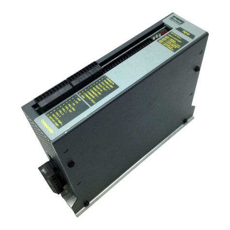
Parker Compumotor TQ10 user guide
