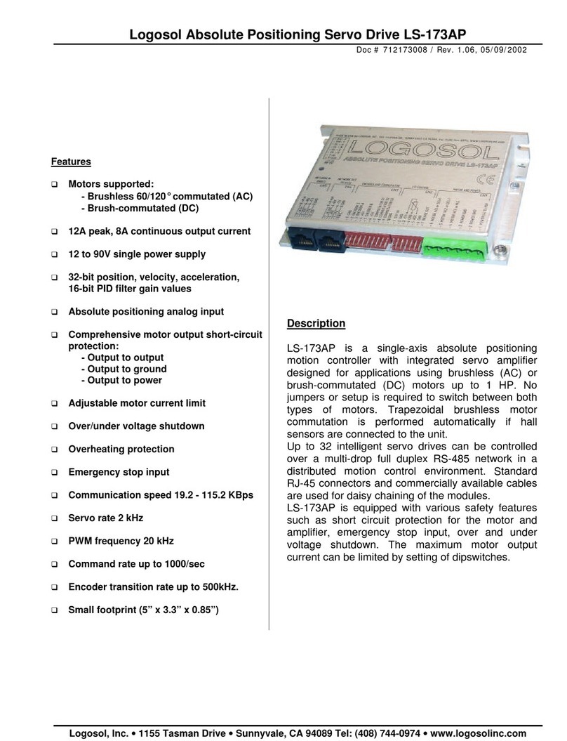
Logosol LS-231SE User manual

Logosol Multifunctional Servo Drive LS-231SE
Doc # 712231004 / Rev. A, 05/05/2011
Logosol, Inc. •1155 Tasman Drive •Sunnyvale, CA 94089 Tel: (408) 744-0974 •www.logosolinc.com
Features
Controller modes:
- Distributed Servo
- Analog ±10V
- Quadrature Encoder mode
- Step & Direction
- Step Positive/Step Negative
Dual Encoder Loop
Servo loop rate 51.2uS
Sinusoidal motor phases commutation
Motors supported:
- Panasonic A and S series motors
- Brushless 60/120°commutated
- Linear motors
- Voice coil and Brush motors
Up to 20A peak / 12A continuous output
current
Up to 200V DC power supply
Path point buffer for coordinated motion
control
32-bit position, velocity, acceleration,
16-bit PID filter gain values
Torque loop
Safety Bus
Feedback loss protection
Comprehensive motor output short-circuit
protection:
- Output to output
- Output to ground
Adjustable motor current and overload time
limits
Over/under voltage shutdown
Overheating protection
Forward and reverse over travel inputs
Communication 19.2Kb/S to 1.25Mb/S
PWM frequency 20 kHz
Encoder rate 10.0MHz
Description
LS-231SE is all digital multifunctional single-axis
servo controller with integrated power amplifier
designed for applications requiring sinusoidal control
of Rotary or Linear brushless motors up to 1.5 HP.
DC (brush) and Voice coil motors are also
supported.
In LDCN mode the drive supports coordinated
motion of several motors. Up to 31 devices can be
controlled over a multi-drop full duplex RS-485
network. Standard RJ-45 connectors and
commercially available cables are used for daisy
chaining of the modules.
In Analog modes the drive supports precise speed
control. Analog modes give flexible use of Analog,
Enable and Direction inputs.
Three modes are provided in addition to the
standard Step & Direction mode. In Step
Positive/Step Negative mode the direction is
controlled via two separate step inputs. In
Quadrature encoder modes step and direction
inputs can be connected to A and B phase of an
incremental encoder.
Dual-Loop encoder mode supports two encoder
inputs. In this mode the encoders for position and
servo control are separated. High resolution
encoders can be used for precise position control.
LS-231SE is equipped with various safety features
such as short circuit protection for the motor and the
drive, limit switch inputs, over/under voltage
shutdown and encoder presence control. Safety bus
can be connected for multi-drive system protection.
The maximum motor output current and overload
time can be set.

Logosol Multifunctional Servo Drive LS-231SE
Doc # 712231004 / Rev. A, 05/05/2011
Logosol, Inc. •1155 Tasman Drive •Sunnyvale, CA 94089 Tel: (408) 744-0974 •www.logosolinc.com 2
TECHNICAL SPECIFICATIONS rated at 25oC ambient, POWER (+)=60VDC, Load=250μH motor
+POWER
18 to 180Vdc, 200V Absolute Maximum
+24V 18Vdc to 36Vdc I/O power supply
+24V Backup Current 0.25A Maximum
MAX MOTOR OUTPUT CURRENT
Peak
Continuous
20A
12A
MIN LOAD INDUCTANCE 200μH
PWM SWITCHING FREQUENCY 19.5KHz
SERVO RATE 51.2 µSec
SERIAL BAUD RATE 19.2Kb/Sec to 1.25 Mb/Sec
DIGITAL OUTPUTS
Source driver
Brake/Output1 (CN1pin4)
Pull-Up (CN2pin1, CN5pin6, CN9pin8)
Output2 (CN2pin3)
Fault (CN8pin9)
24V (18Vdc to 36Vdc Maximum). Short protection. Output clamp diode.
0.3A
0.1A for all outputs combined
0.2A
HImin=4V, LOmax=0.4V Iout=4mA
RELAY OUTPUTS
LIMIT, FAULT
Relay contact
ANALOG OUTPUT
DACout
0 to +5V/1mA
DIGITAL INPUTS
+A, -A, +B, -B, +Z, -Z, +Rx/H1, -Rx/H2
Limit1, Limit2, HomeIN, Input9, Enable,
Input10, Input11
Dir, AEN, Step (CN8pin7, pin12, pin13)
HI=3.5V, LO=1.5V, 2K2 pull-up resistors
LOmin=-0.5V<LO< 6.5V; 15V<HI<HImax=36V;Imax=8mA
HI=3.5V, LO=1.5V, 4K7 pull-down resistors
ANALOG INPUT
ADCin
±10V, 10K to Gnd
ENCODER Quadrature with index. Encoder rate 10MHz max (5MHz max Enc Filter=ON)
Panasonic encoder mode.
HALL SENSORS 60/120 o or Panasonic
LEDs
ORANGE, GREEN, RED
Refer to LS-231SE Diagnostic and I/O section for details
PROTECTION
Short circuit
Over-temperature shut off
Motor output to motor output, Motor output to GND
Activated at 80 oC
POWER DESSIPATION (max) 45W
THERMAL REQUIREMENTS
Storage temperature range
Operating temperature range
–30 to +85 oC
0 to 45 oC
MECHANICAL
Size
Weight
6.5” x 4.0” x 0.85”
0.8 lb. (0.36 kg)
+5V SOURCE
Max output current
200mA for all output pins combined
MATING CONNECTORS
MOTOR AND POWER
I/O
SAFETY BUS
CN9
ENCODER AND COMUTATOR
CN8
NETWORK (HOST, SLAVE)
RECOMMENDED CONNECTOR TYPE
EM2565-08-H Terminal Block 8 Poles 5.08mm
Molex 22-01-3047 housing with 08-50-0114 pins (4 pcs.)
Molex 22-01-3047 housing (2 pcs.) with 08-50-0114 pins (8 pcs.)
Molex 22-01-3087 housing with 08-50-0114 pins (8 pcs.)
AMP 205206-3 D-Shape 15 Pin M Crimp Housing with AMP 5-66507-7(15 pcs.)
3M 34526600 Socket16 pin, polarized 0.1"
8 pin RJ-45

Logosol Multifunctional Servo Drive LS-231SE
Doc # 712231004 / Rev. A, 05/05/2011
Logosol, Inc. •1155 Tasman Drive •Sunnyvale, CA 94089 Tel: (408) 744-0974 •www.logosolinc.com 3
DIMENSIONAL DRAWING
6.220
6.500
0.750
2.000
4.000
0.165
4.250 max
0.16
5
0.500
0.850
SERVO DRIVE LAYOUT
ORDERING GUIDE
PART NUMBER MODEL DESCRIPTION
912231010 LS-231SE- 2020
Multifunctional servo drive 20A/180V
230601051 LS-231-CN
Mating connector kit for LS-231SE
230601017 PAN-AS-CN
Mating connector kit for Panasonic A and S series motors
230601027 PAN-ASB-CN
Mating connector kit for Panasonic A and S series motors with brake
922231100 LS-2311 Dual-loop master encoder interface

Logosol Multifunctional Servo Drive LS-231SE
Doc # 712231004 / Rev. A, 05/05/2011
Logosol, Inc. •1155 Tasman Drive •Sunnyvale, CA 94089 Tel: (408) 744-0974 •www.logosolinc.com 4
CONECTORS AND PINOUT
DIP SWITCHES
SW NAME DESCRIPTION
1 Terminator Tx Transmit line terminator
2 Terminator Rx Receive line terminator
3 Reserved Reserved must be off
4 Reserved Must be off.
5 Sw5
6 Sw6
Sw6=ON, Sw5=ON - Motor with single ended (non differential) encoder
Sw6=ON, Sw5=OFF - Motor with differential encoder
Sw6=OFF, Sw5=ON - Panasonic A or S series motor (P-mode)
Sw6=OFF, Sw5=OFF - Reserved
CONNECTORS
CN1 – POWER AND MOTOR
PIN SIGNAL DESCRIPTION
1 +POWER 18Vdc TO 90Vdc Power supply positive terminal
2 +24V 18Vdc TO 36Vdc I/O power supply
3 POWER Gnd Power supply ground
4 Brake/Output1 Brake output
5 Gnd I/O ground
6 MOTOR AC3 (W)
Output to motor
Phase 3 terminal for brushless motors
Phase W for Panasonic A and S series motors
Negative terminal for DC and Voice Coil motors
7 MOTOR AC2 (V)
Output to motor
Phase 2 terminal for brushless motors
Phase V for Panasonic A and S series motors
Positive terminal for DC and Voice Coil motors
8 MOTOR AC1 (U)
Output to motor
Phase 1 terminal for brushless motors
Phase U for Panasonic A and S series motors
Not connected for DC and Voice Coil motors

Logosol Multifunctional Servo Drive LS-231SE
Doc # 712231004 / Rev. A, 05/05/2011
Logosol, Inc. •1155 Tasman Drive •Sunnyvale, CA 94089 Tel: (408) 744-0974 •www.logosolinc.com 5
CN2 – I/O
PIN SIGNAL DESCRIPTION
1 Gnd Signal ground
2 Output2 Multifunctional output (mode dependent)
3 Input10 Multifunctional input (mode dependent)
4 Pull-Up Protected power output (+24V)
SAFETY BUS
CN3
PIN SIGNAL DESCRIPTION
1 LIMIT Limit relay contact (CN3)
2 Input9 Limit input
3 FAULT Fault relay contact (CN3)
4 Enable Drive Enable/Stop input
CN4
PIN SIGNAL DESCRIPTION
1 LIMIT Limit relay contact (CN4)
2 Input9 Limit input
3 FAULT Fault relay contact (CN4)
4 Enable Drive Enable/Stop input
CN5 – ENCODER AND COMMUTATOR
PIN SIGNAL DESCRIPTION
1 -Rx/H2
Hall input #2 for brushless motors
Hall data for Panasonic A or S series motors
Not connected for DC motors
2 Enc 5V Encoder +5V power supply
3 -Z/H3
Hall input #3 for brushless motors
Encoder index (-)Z for Panasonic A or S series motors and DC motors with differential
encoder
4 -B/NA Encoder phase (-)B for motors for motors with differential encoder
5 -A/NA Encoder phase (-)A for motors for motors with differential encoder
6 Pull-Up Protected power output (+24V)
7 Limit1 Limit1 input (connected to CN9-4 through 1K resistor)
8 Gnd Signal ground
9 +Rx/H1
Hall input #1 for brushless motors
Hall data for Panasonic A or S series motors
Not connected for DC motors
10 Gnd Encoder ground
11 +Z Encoder index Z
12 +B Encoder phase B
13 +A Encoder phase A
14 HomeIN Home input (connected to CN9-6 through 1K resistor)
15 Limit2 Limit2 input (connected to CN9-2 through 1K resistor)
CN6 –SLAVE
PIN SIGNAL DESCRIPTION
1 N.C. Not connected
2 Gnd Interface ground
3 +Tx (+) Transmit data
4 -Tx (-) Transmit data
5 -Rx (-) Receive data
6 +Rx (+) Receive data
7 -A out (-) Address output
8 +A out (+) Address output
CN7 –HOST
PIN SIGNAL DESCRIPTION
1 +5V RS-232 adapter power supply
2 Gnd Interface ground
3 +Tx (+) Transmit data
4 -Tx (-) Transmit data
5 -Rx (-) Receive data
6 +Rx (+) Receive data
7 -A in (-) Address input
8 +A in (+) Address input

Logosol Multifunctional Servo Drive LS-231SE
Doc # 712231004 / Rev. A, 05/05/2011
Logosol, Inc. •1155 Tasman Drive •Sunnyvale, CA 94089 Tel: (408) 744-0974 •www.logosolinc.com 6
CN8
PIN SIGNAL DESCRIPTION
1 -A Encoder phase (-) A output. Wired to CN5pin5
2 +A Encoder phase A output. Wired to CN5pin13
3 -B Encoder phase (-) B output. Wired to CN5pin4
4 +B Encoder phase B output. Wired to CN5pin12
5 -Z Encoder phase (-) Z output
6 +Z Encoder phase Z output. Wired to CN5pin11
7 Dir
LDCN Single and Dual-loop modes – NA
Analog input Single/Dual-loop mode – NA
Analog input mode with direction invert input – Direction input
Enable Positive/Enable Negative Analog input mode – Enable + Direction input
Step & Direction mode – Direction input
Step Positive/Step Negative mode – Negative Step input
Quadrature encoder mode – Counter A input
8 Gnd Signal ground
9 Fault Fault output
10 Gnd Signal ground
11 +5V +5V power supply
12 AEN
LDCN Single loop mode – NA
LDCN Dual-loop mode – Secondary encoder error
All other modes – Enable input
13 Step
LDCN Single and Dual-loop modes – NA
All Analog modes – NA
Step & Direction mode – Step input
Step Positive/Step Negative mode – Positive Step input
Quadrature encoder modes – Counter B input
14 AnGnd Analog ground
15 ADCin Analog input 0 to ±10V
16 DACout Analog output 0 to +5V
CN9
PIN SIGNAL DESCRIPTION
1 Gnd Signal ground
2 Limit2 Limit2 (connected to CN5-15 through 1K resistor)
3 Gnd Signal ground
4 Limit1 Limit1 (connected to CN5-7 through 1K resistor)
5 Gnd Signal ground
6 Home Home (connected to CN5-14 through 1K resistor)
7 Input11 Multifunctional input (mode dependent)
8 Pull-Up Protected power output (+24V)

Logosol Multifunctional Servo Drive LS-231SE
Doc # 712231004 / Rev. A, 05/05/2011
Logosol, Inc. •1155 Tasman Drive •Sunnyvale, CA 94089 Tel: (408) 744-0974 •www.logosolinc.com 7
DUAL-LOOP MASTER ENCODER INTEFRACE
LS-231SE1 is master encoder interface for dual-loop applications with LS-231SE Multifunctional Servo
Drive.
DUAL-LOOP MASTER ENCDOER INTERFACE DIMENSIONAL DRAWING
DUAL-LOOP MASTER ENCODER INTERFACE LAYOUT

Logosol Multifunctional Servo Drive LS-231SE
Doc # 712231004 / Rev. A, 05/05/2011
Logosol, Inc. •1155 Tasman Drive •Sunnyvale, CA 94089 Tel: (408) 744-0974 •www.logosolinc.com 8
DUAL-LOOP MASTER ENCODER INTERFACE LS-2311 CONECTORS AND PINOUT
JUMPERS
JUMPER NAME DESCRIPTION
1 CN4 EXT +5V Power supply from CN4pin11
2 CN1 Internal power supply. 12Vdc to 36Vdc power supply from CN1pin1
3 CN3 EXT +5V Power supply from CN3pin7
Note: Only one JUMPER must be shorted.
DIP SWITCHES
SWITCH NAME DESCRIPTION
1 Reserved Reserved must be OFF
2 Reserved Reserved must be OFF
CN1
PIN SIGNAL DESCRIPTION
1 12Vdc to 36Vdc Power supply input. If Power source jumper CN1 is installed
2 Gnd Power supply ground
CN2 – Master Encoder
PIN SIGNAL DESCRIPTION
1 NC Not connected
2 -Z Encoder phase –Z
3 NC Not connected
4 NC Not connected
5 +5V Encoder power supply
6 +B Encoder phase +B
7 Gnd Power supply ground
8 +A Encoder phase +A
9 NC Not connected
10 +Z Encoder phase +Z
11 Reserved Reserved - DO NOT CONNECT
12 +5V Encoder power supply
13 -B Encoder phase –B
14 Gnd Power supply ground
15 -A Encoder phase –A

Logosol Multifunctional Servo Drive LS-231SE
Doc # 712231004 / Rev. A, 05/05/2011
Logosol, Inc. •1155 Tasman Drive •Sunnyvale, CA 94089 Tel: (408) 744-0974 •www.logosolinc.com 9
CN3 – Auxiliary Interface
PIN SIGNAL DESCRIPTION
1 -A Encoder phase –A. Wired to CN2pin15
2 +A Encoder phase +A. Wired to CN2pin8
3 -B Encoder phase –B. Wired to CN2pin13
4 +B Encoder phase +B. Wired to CN2pin6
5 -Z Encoder phase –Z. Wired to CN2pin2
6 +Z Encoder phase +Z. Wired to CN2pin10
7 EXT +5V +5V power supply input. Power jumper CN3 must be installed
8 Gnd Power supply ground
9 Fault Fault output.
10 Gnd Power supply ground
11 +5V +5V Power Supply output
12 AEN Amplifier Enable input
13 NC Not connected
14 AnGnd Analog ground. Wired to CN4pin14
15 ADCin Analog input. Wired to CN4pin15
16 DACout Analog output. Wired to CN4pin16
CN4 – LS-231SE interface
PIN SIGNAL DESCRIPTION
1 DACout Analog output. Wired to CN3pin16
2 ADCin Analog input. Wired to CN3pin15
3 AnGnd Analog ground. Wired to CN3pin14
4 PhB Master encoder phase B output to LS-231SE
5 AEN/Z Amplifier Enable output
6 EXT +5V +5V input Power Source jumper CN4 must be installed
7 Gnd Power supply ground
8 Fault In Fault input from LS-231SE
9 Gnd Power supply ground
10 PhA Master encoder phase A output to LS-231SE
LS-2311 Power Supply Source
LS-231SE Master Encoder Cables

Logosol Multifunctional Servo Drive LS-231SE
Doc # 712231004 / Rev. A, 05/05/2011
Logosol, Inc. •1155 Tasman Drive •Sunnyvale, CA 94089 Tel: (408) 744-0974 •www.logosolinc.com 10
SAMPLE APPLICATION using AC (brushless) motor in LDCN mode
Home switch and limit switches are connected to CN5.
NETWORK HOST
NETWORK SLAVE

Logosol Multifunctional Servo Drive LS-231SE
Doc # 712231004 / Rev. A, 05/05/2011
Logosol, Inc. •1155 Tasman Drive •Sunnyvale, CA 94089 Tel: (408) 744-0974 •www.logosolinc.com 11
SAMPLE APPLICATION using AC (brushless) motor in LDCN mode
Home switch and limit switches are connected to CN8.
NETWORK HOST
NETWORK SLAVE

Logosol Multifunctional Servo Drive LS-231SE
Doc # 712231004 / Rev. A, 05/05/2011
Logosol, Inc. •1155 Tasman Drive •Sunnyvale, CA 94089 Tel: (408) 744-0974 •www.logosolinc.com 12
SAMPLE APPLICATION using Panasonic A or S series motors in Analog input mode

Logosol Multifunctional Servo Drive LS-231SE
Doc # 712231004 / Rev. A, 05/05/2011
Logosol, Inc. •1155 Tasman Drive •Sunnyvale, CA 94089 Tel: (408) 744-0974 •www.logosolinc.com 13
SAMPLE APPLICATION using Panasonic A or S series motors in Step & Direction (Step
Positive/Step Negative) mode

Logosol Multifunctional Servo Drive LS-231SE
Doc # 712231004 / Rev. A, 05/05/2011
Logosol, Inc. •1155 Tasman Drive •Sunnyvale, CA 94089 Tel: (408) 744-0974 •www.logosolinc.com 14
SAMPLE APPLICATION using Panasonic A or S series motors in Quadrature encoder mode
NETWORK HOST
NETWORK SLAVE

Logosol Multifunctional Servo Drive LS-231SE
Doc # 712231004 / Rev. A, 05/05/2011
Logosol, Inc. •1155 Tasman Drive •Sunnyvale, CA 94089 Tel: (408) 744-0974 •www.logosolinc.com 15
SAMPLE APPLICATION Analog Input Dual-Loop mode using Panasonic A or S series motors

Logosol Multifunctional Servo Drive LS-231SE
Doc # 712231004 / Rev. A, 05/05/2011
Logosol, Inc. •1155 Tasman Drive •Sunnyvale, CA 94089 Tel: (408) 744-0974 •www.logosolinc.com 16
SAMPLE APPLICATION LDCN Dual-Loop mode using AC (brushless) motor
Home switch and limit switches are connected to CN5.
CN5-8
NETWORK HOST
Enable/Stop
+24V
BR
NETWORK SLAVE
Optional
Incremental
Encoder
Brake/Output1 (CN1-4)
Brake
(optional)
Gnd (CN1-5)
AC (brushless)
motor
CN9
Limit2
Home
Limit1
Pull-Up

Logosol Multifunctional Servo Drive LS-231SE
Doc # 712231004 / Rev. A, 05/05/2011
Logosol, Inc. •1155 Tasman Drive •Sunnyvale, CA 94089 Tel: (408) 744-0974 •www.logosolinc.com 17
SAMPLE APPLICATION - LDCN Dual-Loop mode using AC (brushless) motor
Home switch and limit switches are connected to CN8.
CN5-8
NETWORK HOST
Enable/Stop
+24V
B
R
NETWORK SLAVE
Optional
Incremental
Encoder
Brake/Output1 (CN1-4)
Brake
(optional)
Gnd (CN1-5)
AC (brushless)
motor
CN9
Limit2
Home
Limit1
Pull-Up

Logosol Multifunctional Servo Drive LS-231SE
Doc # 712231004 / Rev. A, 05/05/2011
Logosol, Inc. •1155 Tasman Drive •Sunnyvale, CA 94089 Tel: (408) 744-0974 •www.logosolinc.com 18
SAMPLE APPLICATION - LDCN mode using Master and Slave motors
NETWORK HOST
NETWORK SLAVE
NETWORK HOST
NETWORK SLAVE
CN8.2 +A
CN8.4 +B
CN8.9 Fault
CN8.8 GND
CN8.7 DIR
CN8.8 GND
CN8.12 AEN
CN8.13 STEP
CN8.4 +B
CN8.2 +A
CN8.8 GND
CN8.9 Fault

Logosol Multifunctional Servo Drive LS-231SE
Doc # 712231004 / Rev. A, 05/05/2011
Logosol, Inc. •1155 Tasman Drive •Sunnyvale, CA 94089 Tel: (408) 744-0974 •www.logosolinc.com 19
SAMPLE APPLICATION – Analog input using Master and Slave motors
CN8.2 +A
CN8.4 +B
CN8.9 Fault
CN8.8 GND
CN8.7 DIR
CN8.8 GND
CN8.12 AEN
CN8.13 STEP
CN8.4 +B
CN8.2 +A
CN8.8 GND
CN8.15 ADCin
CN8.14 AnGnd
CN8.12 AEN
CN8.6 +Z
SERVO CONTROLER
Hold Slave
Fault2
Fault1
Analog Output
Amplifier Enable
Encoder A
Encoder B
Encoder Z

Logosol Multifunctional Servo Drive LS-231SE
Doc # 712231004 / Rev. A, 05/05/2011
Logosol, Inc. •1155 Tasman Drive •Sunnyvale, CA 94089 Tel: (408) 744-0974 •www.logosolinc.com 20
PANASONIC A AND S SERIES MOTORS
WIRING DIAGRAM
ENCODER CONNECTOR
PIN# SIGNAL NAME WIRE COLOR
1 + A channel output Red
2 - A channel output Pink
3 + B channel output Green
4 - B channel output Blue
5 + Z channel output Yellow
6 - Z channel output Orange
7 NC NA
8 NC NA
9 NC NA
10 NC NA
11 +RX Light blue
12 -RX Purple
13 +5V White
14 0V Black
15 FG = motor frame Black
MOTOR CONNECTOR
PIN# SIGNAL NAME WIRE COLOR
1 U phase Red
2 V phase White
3 W phase Black
4 E = motor frame Green/yellow
BRAKE CONNECTOR (Optional)
PIN# SIGNAL NAME WIRE COLOR
1 Brake Yellow
2 Brake Yellow
EXTENSION CABLE
To LS-231SE
MOTOR CONNECTOR
AMP CAP 172163-1
10 pins 170365-1
LS-231SE CONNECTOR
AMP 205206-3 D-Shape 15 Pin
Male Crimp Housing
15 pins AMP 5-66507-7
PIN# SIGNAL NAME PIN# SIGNAL NAME
1 + A channel output 13 +A
2 - A channel output 5 -A
3 + B channel output 12 +B
4 - B channel output 4 -B
5 + Z channel output 11 +Z
6 - Z channel output 3 -Z
11 +RX 9 +RX
12 -RX 1 -RX
13 +5V 2 Enc +5V
14 0V 10 Gnd
FG SHIELD 8 Gnd (SHIELD)
NA NA 6 Pull-Up
NA NA 14 HomeIN
NA NA 7 Limit1
NA NA 15 Limit2
To LS-231SE
MOTOR CONNECTOR
AMP CAP 172159-1
4 pins 170366-1
LS-231SE CONNECTOR
PHOENIX CONTACT
MSTB2.5/8-ST-5.08
PIN# SIGNAL NAME PIN# SIGNAL NAME
1 U phase 8 MOTOR AC1 (U)
2 V phase 7 MOTOR AC2 (V)
3 W phase 6 MOTOR AC3 (W).
4 E=motor frame (SHIELD)
BRAKE (OPTIONAL)
AMP CAP 172157-1
2 pins 170366-1
LS-231SE CONNECTOR
PHOENIX CONTACT
MSTB2.5/8-ST-5.08
PIN# SIGNAL NAME PIN# SIGNAL NAME
1 Brake 4 Brake/Output1
2 Brake 5 Gnd
Table of contents
Other Logosol Servo Drive manuals