manuals.online logo
Brands
  1. Home
  2. •
  3. Brands
  4. •
  5. YASKAWA
  6. •
  7. Servo Drive
  8. •
  9. YASKAWA HR Series User manual

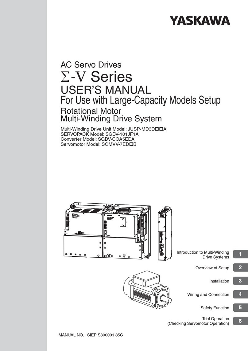
YASKAWA HR Series User manual

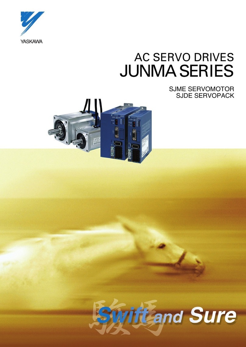
AC SERVO DRIVES HR SERIES
DESCRIPTIVE MANUAL
FOR MULTI-FUNCTIONS/POSITIONING CONTROL
SERVOMOTOR M,F,G,D,S,R,P SERIES
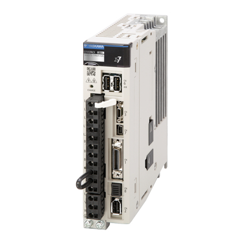
SERVOPACK CACR-H Ri_ii_i BAD(RACK-MOUNTED TYPE)
CACR-HRI_ji_iBB (BASE-MOUNTED TYPE)
V
YASKAWA TSE-S800-6H
Yaskawa AC Servos have been developed for the most advanced FA and FMS. The extensive
servo manufacturing technology accumulated through half a century of servo drive
applications has created this series.
AC Servopack CACR-HRis a general-purpose multi-function position controller which
applies YASKAWA'slong-term positioning control technologies to software.
In addition to realization of high-accuracy and quick response control even under
adverse conditions, easy and flexible operation is available with excellent
maintainability due to various display functions and protective functions.
CAUTION l-_'-=_
Neveruse voltage resistanceor
ITleggertester.
ServopackS(Rack.mountedType) _111
[ 1__ 589-264
• _ ,d 589 266
_8995
|
AC Servomotors Servopacks Mli
(Base-mounted Type)
I
390-37
General Precautions
•Some drawings in this manual are shown with the protective coveror shields I
'qg
removed, in order to describe the detail with more clarity. Make sure all covers
and shields are replaced before operating this product.
•Some drawings in this manual are shown as typical example and may differ from
the shipped product.
• This manual may be modified when necessary because of improvement of the
product, modification,or changes in specifications.
Such modification is made as a revision by renewing the manual No.
• To order a copy of this manual, if your copy has been damaged or lost, contact
your YASKAWA representative listed on the last page stating the manual No. on
the front cover.
• YASKAWA is not responsible for accidents or damages due toany modification
of the product made bythe user since that will void our guarantee. •
1
NOTES FOR SAFE OPERATION
Read this manual thoroughly before installation, operation,mainte-
nance or inspection of the AC Servo Drives. In this manual,the
NOTES FOR SAFE OPERATION are classified as "WARNING"
or "CAUTION."
WARNING[
Indicates a potentially hazardous situation which,if not avoided,
could result in death or serious personal injury.
P
CAUTION
Indicates a potentially hazardous situation which, if not avoided,
may result in minor or moderate personal injury and/or damage to
the equipment.
In some instances,items described in ]_ CAUTION]may also result in
a serious accident. In either case,follow these important items.
/WARNING
(WIRING)
• Grounding must be in accordance with the national code and consistent with
sound local practices.
Failure to observe this warning may lead to electric shock or fire.
(OPERATION)
• Never touch any rotating motor parts during operation.
Failure to observe this warning may result in personal injury.
(INSPECTION AND MAINTENANCE)
• Never open the panel cover while power is ON, and never turn ON power
when the panel cover is open.
Otherwise, electric shock may result.
• After turning OFF power,wait at least five minutes before servicing the
product.
Otherwise, residual electric charges may result in electric shock.
- 1 -
CAUTION
(RECEIVING)
• Use the specified combination of SERVOMOTOR and SERVOPACK.
Failure to observe this caution may lead to fire or failure.
(INSTALLATION)
•Never use the equipment where it may be exposed to splashes of water,
corrosive or flammable gases, or near flammable materials.
Failure to observe this caution may lead toelectric shock or fire.
(WIRING) 1
• Do not connect three-phase power supply to output terminals @ @ and @.
Failure to observe this caution may lead to personal injury or fire.
• Securely tighten screws on the power supply and motor output terminals.
Failure to observe this caution can result in a fire.
(OPERATION)
,d
• To avoid inadvertent accidents, run the SERVOMOTOR only in test run ql
(without load).
Failure to observe this caution may result in personal injury.
• Before starting operation with a load connected, make sure emergency-stop
procedures are in place.
Failure toobserve this caution may result in personal injury.
•During operation, donot touch the heat sink, regenerative resistance,
SERVOMOTOR and other peripheral devices, il
Failure to observe this caution may result in burns.
• When Serve Alarm goes off, determine cause and confirm safety before
resetting alarm and resuming operation.
Failure to observe this caution may result in personal injury.
(INSPECTION AND MAINTENANCE)
• Do not disassemble the SERVOMOTOR.
Failure toobserve this caution may result in electric shock or personal
injury.
• Never change wiring while power is ON.
Failure to observe this caution may result in electric shock or personal
injury. 1
- 2 -
OUTLINE 9
TYPE DESIGNATION AND CONFIGURATION 12
RATINGS AND SPECIFICATIONS OF AC SERVOMOTOR 18
_4 RATINGSANDSPECIFICATIONSOFAC SERVOPACK 44
_C_ONNECTION 55
_6 I/0 SIGNAL OPERATION AND FUNCTIONS 95
SERIALCOMMUNICATION 121
_8 PARAMETERS 145
DISPLAY/SETTING/MONITOR FUNCTIONS 182
_0 INSTAL_TION AND WIRING 197
1 TEST RUN,MAINTENANCE, AND INSPECTION 201
_2 PERIPHERALDEVICES 223
3 DIMENSIONS 250
D
_4 APPENDIX PARAMETERSETTING 278
m3D
CONTENTS
Page Page
1. OUTLINE .................................................................. 9 5.1.1 Basic Connection ................................................... 55
2.TYPE DESIGNATION AND CONFIGURATION .................. 12 5.1.2 Typical Connection at Positioning
by Station No. -..................................................... 56
2.] TYPE DESIGNATION ............................................. 12 5.1.3 Typical Connection at Positioning
2.2 COMBINATION OF ACSERVOPACK by DG-SW Data ................................................... 5?
AND SERVOMOTOR ............................................. 14
2.3 CONFIGURATION WITH 5.1.4 Typical Connection at Positioning
by Serial Communication ....................................... 59
PERIPHERAL DEVICES .......................................... 17
3. RATINGSAND SPECIFICATIONS 5.1.5 Typical Connection at Positioning
by Command Table ................................................ 60
OF AC SERVOMOTOR ................................................ 18
5.2 MAIN CIRCUIT TERMINAL NAMES
3.1 RATINGS AND SPECIFICATIONS ........................... 18 AND OUTLINE ...................................................... 61
3.1.1 M Series ............................................................... 18 5.3 CONNECTOR TERMINAL (2CN)
3.1.2 F Series ............................................................... 20 FOR I/O SIGNAL ................................................... 61
3.1.3 G Series ............................................................... 22 5.3.1 Applicable Receptacle Specifications ........................ 61
3.1.4 D Series ............................................................... 24 5.3.2 Connector 2CN Layout and Connection ..................... 62
3.1.5 S Series ............................................................... 26 5.3.3 Description and Usage of I/O Signals
of Connector 2CN ................................................... 64
3.1.6 R Series (For 200V) ............................................. 28
5.4 CONNECTOR TERMINAL (3CN)
3.1.7 R Series (For 100V) ............................................. 30 FOR ENCODER .......................................... "........... 65
3.1.8 P Series ............................................................... 32 5.4.1 Applicable Receptacle and Cable Specifications ......... 65
3.2 MECHANICAL CHARACTERISTICS ........................ 34 5.4.2 Connector 3CN Layout and Connection ..................... 67 •
1
3.2.1 Mechanical Strength ............................................. 34 5.5 CONNECTOR TERMINAL (4CN)
3.2.2 Allowable Radial Load and Thrust Load .................. 34 FOR I/O SIGNAL ................................................... 70
3.2.3 Mechanical Specifications ....................................... 35 5.5.1 Applicable Receptacle ............................................. 70
3.2.4 Rotating Direction ................................................ 35 5.5.2 Connector 4CN Layout and Connection ..................... 70
3.2.5 Shock Resistance ................................................... 35 5.5.3 Description and Usage of I/O Signals
of Connector 4CN ................................................ 72
3.2.6 Vibration Resistance ............................................. 35
5.6 CONNECTOR TERMINAL (5CN)
3.2.7 Vibration Class ...................................................... 35 FOR I/O SIGNAL ................................................... 73
Jml
3.3 RECEPTACLES ...................................................... 36 5.6.1 Applicable Receptacle Specifications ........................ 73 I
3.3.1 Connector Specifications ....................................... 36 5.6.2 Connector 5CN Layout and Connection ..................... 73
3.3.2 List of Standard Combination ................................. 40 5.6.3 Description and Usage of I/O Signals
4. RATINGSANDSPECIFICATIONS OFof Connector 5CN ................................................ 80
AC SERVOPACK ......................................................... 44 5.7 POWER SUPPLY CONNECTION .............................. 86
4.1 RATINGS AND SPECIFICATIONS ........................... 44 5.7.1 Power Supply ON/OFF ........................................ :'86
4.2 INTERNAL BLOCK DIAGRAM .............................. 46 5.7.2 Power Supply Line Protection ................................. 88
4.3 PROTECTIVE CIRCUIT .......................................... 495.8 RATED CURRENT AND TYPICAL
APPLICABLE CABLE SIZE .............. ....................... 89
4.4 PRECAUTIONS FOR APPLICATION ........................ 52
5.9 NOISE CONTROL .................................................... 91
4.4.1 Overhanging Load .................................................. 52
4.4.2 Load Inertia (JL) ................................................ 52 6. I/OSIGNALOPERATIONAND FUNCTIONS ..................... 95
4.4.3 Allowable Cyclic Operating Frequency ..................... 52 6.1 OPERATION AND FUNCTIONS OF 2CN
4.4.4 High Voltage Line ................................................ 53 INPUT SIGNAL ...................................................... 95 •
I
4.5 POWERLOSS ......................................................... 54 6.1.1 Signal Timing ...................................................... 95
5. CONNECTION ............................................................ 55 6.1.2 Input Circuit (Refer toFig. 5.7for Connection.) ......... 95
5. I TYPICAL CONNECTION ....................................... 55 6.1.3 Signal Operation and Functions .............................. 96
-- 4-- I
CONTENTS
DPage Page
6.2 OPERATION AND FUNCTIONS OF 5CN 10.2INSTALLATION .................................... "........... 197
INPUT SIGNAL .... ............................................... 101
10.2.1 Servomotor ...................................................... 197
6.2.1 Signal Timing ...................................................... 101 10.2.2 Servopack ......................................................... 199
6.2.2 Input Circuit (Refer to Figs. 5.14, 5.15 and
10.3 WIRING PRECAUTIONS ....................................... 200
5.16 for Typical Connection.) ................................. 101
11. TEST RUN,MAINTENANCE,ANDINSPECTION............ 201
6.2.3 Signal Operation and Functions .............................. 102 11.1CHECK ITEMS BEFORE TEST RUN ....... .............. 201
6.3 OPERATION AND FUNCTIONS OF
2CN/5CN OUTPUT SIGNAL ................................. 114 11.1.1 Servomotor ...................................................... 201
6.3.1 OutputCircuit 11.1.2 Servopack ......................................................... 201
(Referto Figs. 5.7, 5.14and 5.15.)........................... 114 11.2 TEST RUN PROCEDUREs .................................... 202
6.3.2 Signal Operation and Functions .............................. 114 11.2.1 Test-run Preparations .......................................... 202
7.SERIALCOMMUNICATION.......................................... 121 11.2.2 OPeration Check ................................................ 209
7.1 SPECIFICATIONS ................................................ 121 11.3 SERVO PERFORMANCEADJUSTMENT ............... 213
7.2 CONTROL CONFIGURATION .............................. 121
11.3.1. Parameter Setting ............................................. 213
7.3 COMMAND TRANSMISSION
(MASTER CONTROLLER --,SERVOPACK) ............ 122 11.3.2 Adjusting Method-Kp, Kv' Optimum Setting ............ 214
7.3.1 Transmission Method .......................................... 122 11.4INSPECTION AND MAINTENANCE ..................... 215
7.3.2 How to Use Axis Address .................................... 123 11.4.1 AC Servomotor ................................................... 215
7.4 TRANSMISSION DATA 11.4.2 Servopack ......................................................... 215
(SERVOPACK --* HOST CONTROLLER) .................. 124 11.4.3 Battery Replacement .......................................... 216
7.5 SERIAL COMMUNICATION AND TYPICAL 11.5 TROUBLESHOOTING GUIDE .............................. 217
SERVOPACK RESPONSE ..................................... -'125
11.5.1 AC Servomotor ................................................... 217
7.6 SERIAL COMMUNICATION CONTROL CODE ......... 125
11.5.2 Servopack ......................................................... 218
7.7 AUTOMATIC TRANSMISSION DATA
FROM SERVOPACK ............................................. 126 12. PERIPHERALDEVICES............................................. 223
7.8 SERIAL COMMAND ............................................. 129 12.1 COMBINATION OF PERIPHERAL DEVICES ......... 223
7.8.1 Serial Command List ............................................. 129 12.2 BRAKE POWER SUPPLY .................................... 227
7.8.2 Command Functions ................................... ;......... 130 12.3 BRAKING RESISTOR UNIT
(TYPE JUSP-RA03) ............ ................................. 229
8. PARAMETERS......................................................... 145
12.4 EXTERNAL POSITION INDICATOR
8.1 GENERAL PROCEDURE F0R DEFINING PARAMETERS ......... 145 (TYPE MCIF-L8[_]) ............................................. 230
8.2 PARAMETER LIST ................................................ 149 12.5 DIGITAL SWITCH UNIT (TYPE MCIF-D[_][_]) ...... 232
8.3 PARAMETER FUNCTION DETAILS ..................... 157 12.6 CONTACT INPUT UNIT (TYPE MCIF-R86) ......... 234
9. DISPLAY/SE'I-FING/MONITORFUNCTIONS.................. 182 12.7 MANUAL PULSE GENERATOR
9.1 DISPLAY AND SETTING FUNCTIONS .................. 182 (TYPE PREH-2C3T/100-M1) ................................. 236
9_1.1 Display ............................................................... 182 12.8 CONNECTING CABLE .......................................... 238
12.9 PARAMETER SETTER (PF803) ........................... 239
9.1.2 Display and Setting Functions for Servopack
Type CACR-HR[-_]BAB[-__] .............................. 184 12.9.1 Specifications ................................ :.................. 239
9.1.3 Display and Setting Functions for Servopack 12.9.2 External View ................................................... 242
Type CACR-HR[_I_]BB ....................................... 190
12.9.3 How to Use ................................ _..................... 243
9.2 MONITOR FUNCTION .......................................... 195
9.2.1 Servopack Type CACR-HR[_I_]BAB[_] ............... 195 13.DIMENSIONS ......................................................... 250
9.2.2 Servopack Type CACR-HR[_:_]BB ........................ 196 13.1 ACSERVOMOTORWITHABSOLUTEENCODER............... 250
10. INSTALLATIONAND WIRING ............................. "....... 197 13.2 ACSERVOMOTORWITHINCREMENTALENCODER-"........ 266
10_1 RECEIVING ......................................................... 197 13.3 SERVOP.ACK ...................................................... 276
- 5-
CONTENTS (cont'd)
Page Page
13.3.1 Rack-mounted Type CACR-HR[_I_]BAB[_I_] ......... 276 14.7 PARAMETER CHECK LIST ................................. 284
13.3.2 Base-mounted Type CACR-HR[_Z=_]BB .................. 277 14.7.1 Parameters Related to Motor Used ........................ 284
14. APPENDIX PARAMETER SETTING ........................... 278 14.7.2 Parameters Related to Machine
Specifications ................................................... 285
14.1 APPLICATIONS ................................................... 278
14.7.3 Parameters Related to Position
14.2ORDER ELECTRICAL DEVICES ........................... 278
Reference Method ............................................. 287
14.3 MACHINE CONFIGURATION .............................. 279
14.7.4 Speed Reference Method .................................... 287
14.4 SPECIFICATIONS ................................................ 279
14.7.5 Parameters Related to Position Control .................. 288
14.5 SPEED DIAGRAM ................................................ 280 14.7.6 Selection Function ............................................. 288
14.6PARAMETER SETTING TABLE ........................... 281
INDEX
_ section No. Page Section No. Page
AC Servomotor .......................................... 11.4.1 ............ 215 COMBINATION OF PERIPHERAL
DEVICES ................................................... 12.1 ............ 223
AC Servomotor .......................................... 11.5.1 ............ 217
Command Functions .................................... 7.8.2 ............ 130
AC SERVOMOTORWITH ABSOLUTE ENCODER ...... 13.1 ............ 250
COMMAND TRANSMISSION
AC SERVOMOTORWITH INCREMENTAL ENCODER 13.2 ............ 266 (MASTER CONTROLLER --*SERVOPACK)7.3............... 122
Adjusting Method-Kp, Kv' CONFIGURATION WITH
Optimum Setting .......................................... 11.3.2 ............ 214 PERIPHERAL DEVICES ........................... 2.3 ............... 17
Allowable Cyclic Operating Frequency ......... 4.4.3 ............... 52 CONNECTING CABLE ............................. 12.8 ............ 238
• Allowable Radial Load and Thrust Load ......... 3.2.2 ............... 34 CONNECTION .......................................... 5 .................. 55
APPENDIX PARAMETER SETTING ......... 14 ............... 278 Connector 2CN Layout and Connection ......... t5.3.2 ............... 62
Applicable Receptacle Specifications ............ 5.3.1 ............... 61 Connector 3CN Layout and Connection ......... 5.4.2 ............... 67
Applicable Receptacle and Connector 4CN Layout and Connection ......... 5.5.2 ............... 70
Cable Specifications .................................... 5.4.1 ............... 65 Connector 5CN Layout and Connection ......... 5.6.2 ............... 73
Applicable Receptacle ................................. 5.5.1 ............... 70 Connector Specifications .............................. 3.3.1 ............... 36
Applicable Receptacle Specifications ............ 5.6.1 ............... 73
CONNECTOR TERMINAL
APPLICATIONS ....................................... 14.1 ............ 278 (2CN) FOR I/O SIGNAL .............................. 5.3 ............... 61
AUTOMATIC TRANSMISSION CONNECTOR TERMINAL
DATA FROM SERVOPACK ........................ 7.7 ............... 126 (3CN) FOR ENCODER ................................. 5.4 ............... 65
_] CONNECTOR TERMINAL
(4CN) FOR I/O SIGNAL .............................. 5.5 ............... 70
CONNECTOR TERMINAL
Base-mounted Type CACR-HR[_]BB......... 13.3.2 ............ 277 (5CN) FOR I/O SIGNAL .............................. 5.6 ............... 73
Basic Connection ....................................... 5.1.1 ............... 55 CONTACT INPUT UNIT
Battery Replacement .................................... 11.4.3 ............ 216 (TYPE MCIF-R86) ................................... 12.6 ............ 234
BRAKE POWER SUPPLY ........................... 12.2............ 227 CONTROL CONFIGURATION .................. 7.2 ............... 121
BRAKINGRESISTORuNIT
(TYPE JUSP-RA03) .................................... 12.3 ............ 229
lu/
-_ Descriptionand Usage of I/0 Signals of Connector 2CN "'5.3.3 ............... 64
Description andUsage of I/0 Signals ofConnector 4CN --.5.5.3 ............... 72
CHECK ITEMS BEFORE TEST RUN ......... 11.1 ............ 201 Description and Usage of I/0 Signalsof Connector 5CN ...5.6.3 ............... 80
COMBINATION OF AC SERVOPACK DIGITAL SWITCH UNIT
AND SERVOMOTOR ................................. 2.2 ............... 14 (TYPE MCIF-D[_I_i) ................................. 12.5 ............ 232
-- 6--
I
__ i
INDEX
SectionNO. Page SectionNo. Page
DIMENSIONS .......................................... 13 ............... 250
i,v,i
Display ...................................................... 9.1.1 ............ 182
DISPLAY ANDSETTING FUNCTIONS...... 9.1 ............... 182 MACHINE CONFIGURATION..................... 14.3 ............ 279
Display and SettingFunctionsforServopack MAIN CIRCUIT TERMINAL NAMES
TypeCACR-HR[_!BAB'[_i_i ..................... 9.1.2 ............ 184AND OUTLINE .......................................... 5.2 ............... 61
Display and SettingFunctions forServopack
Type CACR-HR[_[:_BB.............................. 9.1.3 ............ 190 MANUAL PULSE GENERATOR
(TYPE PREH-2C3T/100-M1)..................... 12.7 ............ 236
DISPLAY/SETTING/MONITOR
FUNCTIONS ............................................. 9 ............... 182MECHANICAL CHARACTERISTICS......... 3.2.-............. 34
D Series ................................................... 3.1.4............... 24 Mechanical Specifications ........................... 3.2.3............... 35
-]Mechanical Strength ................ :................... 3.2.1............... 34
MONITOR FUNCTION .............................. 9.2 ............... 195
External View ............................................. 12.9.2.. .......... 242 M Series ................................................... 3.1.1 ............... 18
EXTERNAL POSITIONINDICATOR
(TYPE MCIF-L8[_!).................................... 12.4 ............ 230
-_ NOISE CONTROL ...................................... 5.9 ............... 91
F Series ...................................................... 3.1.2............... 20 tO I
t-------J
OPERATION ANDFUNCTIONS
OF2CN INPUT SIGNAL ........................... 6.1 ............... 95
GENERALPROCEDUREFORDEFININGPARAMETERS...... 8.1 ............... 145 OPERATION ANDFUNCTIONS
G Series ................................................... 3.1.3 ............... 22 OF 5CN INPUT SIGNAL ........................... 6.2 ............... 101
OPERATION AND FUNCTIONS
-_ OF2CN/5CNOUTPUT SIGNAL .................. 6.3 ............... 114
Operation Check .......................................... 11.2.2 ............ 209
High Voltage Line ................................ :...... 4.4.4............... 53 ORDER ELECTRICAL DEVICES .................. 14.2 ............ 278
How to Use ................................................ 12.9.3 ............ 243
OUTLINE ................................................ 1 ..................... 9
How to Use Axis Address ........................... 7.3.2 ............ 123
Output Circuit
(Refer to Figs. 5.7, 5.14 and 5.15.).................. 6.3.1 ............ 114Overhanging Load....................................... 4.4.1............... 52
I/O SIGNAL OPERATION
AND FUNCTIONS .................................... 6.................. 95
irl
Input CircuitPARAMETER CHECK LIST ........................ 14.7 ............ 284
(Refer to Fig.5.7 for Connection.) .................. 6.1.2............... 95PARAMETER FUNCTION DETAILS ......... 8.3 ............... 157
Input Circuit (Refer to Figs. 5.14,5.15 and
5.16 for Typical Connection.) ........................ 6.2.2 ............ 101 PARAMETER LIST .................................... 8.2 ............... 149
INSPECTION AND MAINTENANCE ......... 11.4 ............ 215 Parameters Related to Motor Used ............... 14.7.1 ............ 284
INSTALLATION ....................................... 10.2 .......... :.197 Parameters Related to Position
Reference Method .-:.................................... 14.7.3............ 287
INSTALLATION AND WIRING .................. 10 ............... 197
Parameters Related to Position Control ......... 14.7.5 ............ 288
INTERNAL BLOCK DIAGRAM .................. 4.2 ............... 46 PARAMETERS .................... :..................... 8.................. 145
ParametersRelatedtoMachine
Specifications ............................................. 14.7.2............ 285
List of StandardCombination ........................ 3.3.2............... 40PARAMETER SETTER (PF803) .................. 12.9 .......... _"239
Load Inertia(JL).......................................... 4.4.2............... 52 Parameter Setting ....................................... 11.3.1............ 213
-- 7 --
INDEX (cont'd)
Section NO. PageSection No. Page
PARAMETER SETTING TABLE ............... 14.6 ............ 281 SERVOPACK ............................................. 13.3 ............ 276
PERIPHERAL DEVICES ........................... 12 ............... 223 Servopack Type CACR-HR[_I_!BAB[_I_] ...... 9.2.1 ............ 195
POWER LOSS .......................................... 4.5 ............... 54 Servopack Type CACR-HR[_]BB ............... 9.2.2 ............ 196
POWER SUPPLY CONNECTION ............... 5.7 ............... 86 SERVO PERFORMANCE ADJUSTMENT ...11.3 ............ 213
Power Supply Line Protection ..................... 5.7.2 ............... 88 Shock Resistance ....................................... 3.2.5 ............... 35
Power Supply ON/OFF .............................. 5.7.1 ............... 86 Signal Operation and Functions ..................... 6.1.3 ............... 96
PRECAUTIONS FOR APPLICATION ......... 4.4 ............... 52 Signal Operation and Functions ..................... 6.2.3 ............ 102
PROTECTIVE CIRCUIT .............................. 4.3 ............... 49 Signal Operation and Functions ..................... 6.3.2 ............ 114
Signal Timing ............................................. 6.1.1 ............... 95
P Series ...................................................... 3.1.8 ............... 32 Signal Timing ............................................. 6.2.1 ............ 101
-_ SPECIFICATIONS .................................... 7.1 ...............
121
SPECIFICATIONS .................................... 14.4 ............ 279
Rack-mounted Type
CACR-HR[_I_]BAB[_I_] .............................. 13.3.1 ............ 276 Specifications ............................................. 12.9.1 ............ 239
RATED CURRENT AND TYPICAL SPEED DIAGRAM .................................... 14.5 ............ 280
APPLICABLE CABLE SIZE ........................ 5.8 ............... 89 Speed Reference Method .............................. 14.7.4 ............ 287
RATINGS AND SPECIFICATIONS OF S Series ...................................................... 3.1.5 ............... 26
AC SERVOMOTOR .................................... 3 .................. 18
RATINGS AND SPECIFICATIONS ............ 3.1 ............... 18 IT]
RATINGS AND SPECIFICATIONS OF TEST RUN, MAINTENANCE,
AC SERVOPACK ....................................... 4 .................. 44 AND INSPECTION .................................... 11 ............... 201
RATINGS AND SPECIFICATIONS ............ 4.1 ............... 44 Test-run Preparations ................................. 11.2.1 ............ 203
RECEIVING ............................................. 10.1 ............ 197 TEST RUN PROCEDURES ........................ 11.2 ............ 202
RECEPTACLES .......................................... 3.3 ............... 36 TRANSMISSION DATA
(SERVOPACK _ HOST CONTROLLE R) ...... 7.4 ............... 124
Rotating Direction ....................................... 3.2.4 ............... 35
Transmission Method ................................. 7.3.1 ............ 122
R Series (For 100V) ................................. 3.1.7 ............... 30
TROUBLESHOOTINGGUIDE ..................... 11.5 ............ 217
R Series (For 200V) ................................. 3.1.6 ............... 28
TYPICAL CONNECTION ........................... 5.1 ............... 55
Typical Positioning
Connection
at
by Station No.' ............................................ 5.1.2 ............... 56
Selection Function ....................................... 14.7.6 ............ 288 TYPE DESIGNATION AND CONFIGURATION ......... 2 .................. 12
SERIAL COMMAND ................................. 7.8 ............... 129 TYPE DESIGNATION .............................. 2.1 ............... 12
Serial Command List .................................... 7.8.1 ............ 129 Typical Connection at Positioning
SERIAL COMMUNICATION ..................... 7.................. 121 by DG-SW Data .......................................... 5.1.3 ............... 57
SERIAL COMMUNICATION AND Typical Connection at Positioning
TYPICAL SERVOPACK RESPONSE ............ 7.5 ............... 125 by Serial Communication .............................. 5.1.4 ............... 59
SERIAL COMMUNICATION Typical Connectionat Positioningby CommandTable ...... 5.1.5 ............... 60
CONTROL CODE ............... •....................... 7.6 ............... 125
IvJ
Servomotor ................................................ 10.2.1 ............ 197
Servomotor ................................................ 11.1.1 ............ 201 Vibration Class .......................................... 3.2.7 ............... 35
Servopack ................................................ 10.2.2 ............ 199 Vibration Resistance .................................... 3.2.6 ............... 35
Servopack ................................................ 11.1.2 ............ 201
Servopack ................................................ 11.4.2 ............ 215
Servopack ................................................ 11.5.2 ............ 218 WIRING PRECAUTIONS ........................... 10.3 ............ 200
-8-
OUTLINE [
1
Servopack types CACR-UR_2][2]BABand -HR[2][2]BBare single axis position controller
and servo amplifier for AC Servomotor.
Input method of positioning data (speed, position) can be selected from Table 1.1
by setting parameters. Each input method has four operation modes described in Table
1.2. All servo constants are set by parameters. Therefore, adjustment can be per-
formed properly without dispersion.
This manual describes functions and use of Servopaek types CACR-HR[2][2]BABand
-HR[2][2]_BBand to realize their full performance. Read this manual to customize the
use of this drive and improve performance for the machines.
Table1.1Input Method
I InputMethod Description
Serial Communication Positioning dataare input by serial commands.
Input Commandscan be sent to 16 Servopacks with one master controller by
connecting with multi-drop method.
Station No. Input Indexing positioning is performed.
Numbers provided to indexing points (station numbers) are input as
I positiondata.
Speed data are selected from four types of speed set in the Servopack
by parameters, by speed selection signals.
Both "one-way rotation" and "short-cut rotation" are possible.
• Range of station numbers
Binary coded decimal(BCD): 0 to 999
Binary: 0 to 4095
Digital Switch(DG-SW) Positioning data are input by contacts from digital switches, relays
I (Thumbwheelswitch) or sequencers,
Input • Rangeof positioning data
Speed: Up to 6 digits
Position: Sign +up to 8 digits
Note:
According to strobe signal,HRdrive reads DG-SWinput data in time
divisions of 2 digits. Therefore, YASKAWA'sexclusive digital switch
is recommended. Whenanother digital switch or relay is used,use
"contact input unit". Whendata are directly input from thePLC,it
is necessary to set scan time of HR drive (24 to 2000 ms, variable)
to match sequencer scan time.
CommandTable Input Positioning data are selected from the command table set in the
Servopack by using the positioning data selection signals.
D Positioningdata selected in the formof and
are
position
speed
as a pair : Up to 64 patterns can be selected.
-9-
Table 1.20perationModes
OperationMode Contents
Automatic Mode After positioning data are input, positioning is performed based on
the data by turning on start signal.
Manual Mode While manual operation signal is turned on, operation is performed at
constant speed.
Pulse Mode Positioning is performed by pulse train command given by an external
pulse generator.
• Pulse method: Line driver/line receiver method
• Pulse form: 90° phase difference 2-phase pulse train
(up to 1.6 Mpps)
Sign + pulse train (up to 4OOkpps)
CW+ CCWpulse train (up to 400 kpps)
• Pulse multiplication: Xl, XlO, XlO0
Zero-point Used for zero-point return (homing) when incremental encoder is used.
Return (Homing) Mode Two types of methods can be selected.
(1) Decel limit switch and encoder C¢-pulse signal are used.
(2) Only stop limit switch is used.
I Software Revised Version I
Some functions of the CACR-HR type have been added with the revised software. Concerning
the additional functions in Table 1.3, check the software version before use.
Table1.3SoftwareVersionAdjustable for Additional Functions
Software Version
Function
HR[_:]BAB HREJE]BB
Commandtable method and zone signal 3 and upper HRGO06and
upper
Positioning completion signalchange
Positioning commanderror detection
Extension of station No. output, 4 and upper HRGO08and
upper
Addition of Servopack response axis addresses
--10--
Software Version Indication Position
Figs.!. 1 and 1.2 showthe software yersion indications.
sorrwA_ VEaSIO'N
SERVOPACK
CACR-HR f_J i CN
0
I
Fig. 1.1 Software VersionIndication of HR [_[_ BAB
•IC42 _ SOFTWARE
i
LED3
Fig. 1.2Software Version Indication of HR [_[_ BB
--11 --
_.][TYPE DESIGNATION AND CONFIGURATION I
1
2.1 TYPE DESIGNATION
(I) Servomotor
usARES -OS C S 2i_[;i
........
ACSERVO_TOR L OPPOSITEORIVEEND
SPECIFICATION
SERIES*B: S, R,P Series
•AM:MSeries With HoldingBrake
• AF: F Series .E: M, F, G,D Series
•AG:GSeries WithHoldingBrake
•AD: D Series
• AS: S Series _ORIVE ENDSPECIFICATION
• AR: R Series *0: Without Keywaywhen0pp. I
• AP: P Series Drive EndSpecification
I
is Provided.
ENCLOSURE.K:With Keyway
• E: Totally-enclosed, Self- .S: With Oil Seal
cooled Type•T: With Keyway& Oil Seal
•K: Totally-enclosed,
Externally Fan-cooled SHAFTTYPE
Type •i: Taper
•2: Straight
I_.GI_-TTYPE (
oD: Ferrite WITI-IENCODER
•M: Rare Earth
S: 8192 pulses/rev (Absolute)
MOTOROOTPUT W: 1024 pulses/rev (Absolute)
(Refer to Par.2.2) 2:8192pulses/rev (Incremental)
DESIGNREVISIONOR[_._ *1 3:2048 pulses/rev (Incremental)
(A, B, C "-) 4:2500 pulses/rev (Incremental)
(2) Servopack (
CACR- HR 05 B A B 12
J -I ---I
ACSERVOPACKSERIES POWERSUPPLYVOLTAGE
(Provided only for Single-Phase)
CONTROLTYPE I: PowerSupplyVoltagelOOV
Multi-function, 2: Power SupplyVoltage 200V
Positioning Control
MOTOROUTPUT SINGLE-PHASEPOWERSUPPLY
A5:50W (O.OTHP) 01: lOOW (O.13HP) (Providedonlyfor Single-Phase)
02: 200W(0.27HP) 03: 300W(0.40HP) DESIGNREVISIONORDER
05: 500W (0.67HP) 10: 1.0kW(I.3HP) (Blank,B...)
15: 1.5kW(2.0HP) 20: 2.0kW(2.7HP) STRUCTURE
30: 3.0kW(4.1HP) 44:4.4kW(5.9HP) A: Rack-MountedType
60: 6.0kW (8.2HP) B: Base-Mounted Type
SERIES (
General Purpose,
Positioning Control
--12--
*1
Encoder Specification Series Type EncoderSpecification Series Type
Absolute USAMED-O3BS Incremental USAMED-03C3
M to-06C3
8192P/R -60BS 2048P/R M -09B3
to
USAFED-02CS -60B3
F to
-44CS USAFED-02D3
to
USAGEO-O2AS -09D3
Gto F -13C3
-44AS to
USADED-05ES -44C3
D toUSAGED-02C3
-37ESto
-0903
USASEM-O2AS G -t3A3
S to to
-30AS -44A3
USAREM-A5CS(2OOV) USADED-OSE3
R to D to
-07CS -37E3
.USAREM-A5DS(IOOV)
toUSASEM-O2A3
-05DS Sto
-30A3
Absolute USAMED-O3BW
Mto IncrementalUSAMED-O3B2
1024P/R-60BWMto
8192P/R -60B2
USAFED-O2CW
F toUSAFED-O2D2
-44CW-03D2
F-05C2
USAGED-O2AW to
G to -44C2
-44AW
USADED-O5EWUSAGED-02C2
-03C2
D i toG-05A2
!-37EW to
IiUSASEM-O2AW-44A2
to USADED-O5E2
-30AW D to
.USAPEM-OICW -37E2
to IncrementalUSASEM-O2A4
-07CW 2500P/R'S to
-30A4
--13--
2.2 COMBINATION OF AC SERVOPACK AND SERVOMOTOR
Table 2.1 Rack-mounted TypeServopack (200 VAC)4
,figuration, Main Circuit Voltage Rack-mounted Type.Single-phase 200VAC Rack-mounted Type. 3-phase 200VAC
Type CACR-HR A5BABI2 OIBABI2 02BAB12 [ 03BABI2 05BABI2 IOBAB 15BAB
Type US,LMED.... I 03_J_l -- 06 _[_] l 09B _1 12BI!_1
Applicable Output kW 0.3 0.6 0.9 1.2
Servomotor HP -- -- -- 0.4-- 0.81,2 1,6
Speed r/min -- -- -- RatinglO00/Max.2000 -- RatinglO00/Max.2000
:ontinuous OutputCurrent Arms -- -- -- 3.0 -- 5.87.611.7
Max Output Current Arms -- -- -- 7.3 -- 13.916.6 28.0
Allowable Load Inertia kg.cm = 67.5 _ 121.5 183.5 290
IL(=GD2J4)lb,.in.S=x 10-3-- -- -- 60 107.5 162.5 256
TypeUSAFED.... 02 {_J{_1 03 [_]_] 1 05 {_];_] 1 09 ;_;{_]1 I3C _] 2
Applicable kW0.15 O.3 0.45 0.85 1.3
ServomotorOutput 8P -- -- -- 0.2 0.40.6 1.11.7
Speed r/min -- -- -- Rating 1500/Max.2500 Rating 1500/Max.2500
_" Continuous Output Current Arms -- -- -- 3.0 3.0 3.86.2 9.7
MaxOutput :urrent Arms -- -- -- 8. 5 8. 5 11.0 17. 0 27. 6
Allowable kg- ca26.5 10,3 67.5121.5 183.5
I:(=GD2d4) lb.in.S 2x 10-a 5.75 9 60 107.5 162.5
Type USAGED.... 02 [_]{_]I 03 [;;{_]I 05{;]_.i 09 [_]{_;i 13A:{_]2
Applicable kW 0.15 0,30.45 0.85 1.3
Servomotor Output 8P -- -- -- 0.2 0.4O,6I.I1.7 ,1_
I
=" Speed r/min -- -- -- Rating 1500/Max.3000 Rating t500/Max.3000
_"Continuous Output Current Arms -- -- -- 3.0 3.03.87.611.7
Max OntpntCurrent Arms -- -- -- 8.5 8,5 11.0 IT. 028.0
Allowable Load Inertia kg-cm = 6.5 10.3 67.5121.5183.5
JL(=GD=,./4) Ib.in.S _x 10-_ 5.75 0 60 107.5 162.5
Type USADED..... 05E_ _ IOE _]
Applicable kW 0.5 1.0
Servomotor Output HP .... 0,67 -- 1.3
Rating2000 Rating2000 4Speed r/min .... Max. 2500 -- Max. 2500
_.Continuous Output Current Arms .... 3.5 -- 7.9
MaxOutputCurrentArms .... 10.6 -- 25.2
Allowable Load Inertia kg.cm = .... 105 _160
Jt(=GD=J4)lb.in.S =x I0-391 143
TypeUSAS_.- -- -- 02A_i2 03A_i2 05AZ_i2o6A_i2_5A_i2
Applicable Output kW 0.154 0.308 0.462 0.771 1.54
Servomotor HP -- -- 0.20.4 0.6 1.0 2.1
_._o_ Speed r/min -- -- Rsting3000/Max.4000 Rating3000/Max.4000
_"ContinuousOutput Current Arms -- -- 2. I 3.04,2 5. 3 10.4
MaxOutput CurrentArms -- -- 6.0 8.5 11.015.6 28.0
A]]owable Lead [nertia kg,c= =0.652.55 3.75 14.25 16.5
JL(=GD_/4)tb-ln.Stx 10-_ -- -- O.552.253.35 12.65 14.4
4
-- 14--
Table2._Rack-mountedType Servopack(200VAC)(Cont'd)
)efiguration, Main Circuit Voltage Rack-mounted Type, Single-phase 200VAC Rack-mounted Type.3-phase 200VAC
TypeCACR-HR A6BABI2 OIBABI2 02RABI2038AB12 06BABI2IOBAB 16BAR
Type USAREM-A5CS ores02CS 03CS05CS 07CS --
Applicable OutputW 50 100 200300500 700-
ServomotorHP 0.07 0.13 0.27 0.40 0.67 0.94 --
Speed r/min Rating3000/Max.4500Rating 3000/Max,4500 --
_"Continuous Output CurrentArms 0.71 1.02.0 2.7 3,65.7 --
Max Output Current Arms 2. 1 2.8 5. 7 7.8 10.616. 3 --
Allowable Load Inertia kg.cm =0.7751.25 5,0757.65 27.2 37,2
JL(=GD_J4)oz.in.S 2 x 10-_10.817, 8 71.8 109 386 528--
m
Type USAPEM- -- OlCW 02CW 03CW 05CW 07CW --
Applicable Output W _100200 300 500 700
Servomotor HP 0.13 0.27 0.40 0.67 0.94 --
Speed r/min -- Rating 3000/Max.4500 Rating 3000/Max.4500 --
Continuous Output Current Arms -- l.O 2.0 2.7 3.6 5.7--
Max Output Current Arms -- 2.8 5.7 7.810.6 16.3--
Allowable Load Inertia kR "cm 2 _ 1.953. 2 4.9 23. 9 32. 85
JL(=GD'L/4) OZ.in*S =x 10-_ 27. 7545. 15 69. 5339 465 --
Table2.2 Rack-mountedTypeServopack(Single-phaseIOOVAC)
Configuration,Main Circuit Voltage Rack-mounted Type. Single-phase IOOVAC
Type CACR-HR A5BABII OIBABII 02BABII03BABII 05BABI1
Type USAREM- A5DS OIDS 02DS 03DS 05DS
Applicable Output W 50 100 200 300 500
Servomotor HP 0.070.13 0.270.400.67
=,¢,
Speed r/min Rating3000/Max. 4000
Continuous Output Current Arms 1.2 1.7 2.93.6 5.5
MaxOutput Current Arms 3.6 5.0 8.5 10.6 16.3
Allowable Load Inertia kg *cm = O.775 I. 25 5. 0757.6527. 2
JL(=GD=J4) OZ.in.S = x 10-310. 8 17. 871.8 109 386
Note:Combinationof Servomotor and encoder is as shownbelow:
o. of Incremental EncoderAbsolute Encoder @ Standard
s
2048 2500 8192 1024 8192 0 Semi-standard
MSeries • 0 @ 0 @
FSeries 0 @ 0 @
GSeries @. @ @ @
DSeries Q 0 @ ©
SSeries @ 0 @ @
RSeries @
P Series (_)
-15-
Table 2.3 Base-mounted Type Servopack(3-phase 200 VAC)
Configuration. Main Circuit Voltage Base-mountedType.3-phase 200VAC,_
1
TypeCACR-HR 03BB 0588 IOBB 15BB 20BB30BB 44BB 60BB
USAMKO
Type USAMED- 03B [:][:_1 -- 068 [:][:] 109BE:_2 12B[:]220B[:]2 30BE:]2448_:]2-60B _:]2
I Applicable Output kW 0.3 _ 0.6 0.9 1.2 2.0 3.04.4 6.0
Servomotor HP 0.4 0.8 1.2 1.6 2.7 4.05.9 8.0
z= Rating
Speed r/min 1000/-- Rating JO00/Max.2000 Rating lO00/Max.1500
2. Max.2000
ContinuousOutput CurrentArms 3.0-- 5.8 7.6It.718.8 26.0 33.0 45.0
!Max OutputCurrent Arms 7.3 -- 13.9 16.6 28.0 42.0 56.5 70. 0 80. 6
Allowable LoadInertia kg. cm2 67.5121,5183.5 290 550 715 1200 t200
Jt(=GO2J4) Ib. ia, S=× 10-s 60107.5 162. 5 256 486 633• 5 1063 1063
!Type USAFEO- 02 [_][;]1 03 [_][_i 1 I 05it]ill1 09 [_][_i 113C E_]2 20C [_]230C [:]244C _]2--
Applicable Output kW 0.15 0.3 0.45 0,85 1,31.8 2.04.4_
Servomotor HP 0.2 0.4 0.6 1.1 1.7 2.4 3.0 5.9
Speed r/minRating1500/Max.2500 --
_" ContinuousOutput Current Arms 3.0 3.0 3.8 6.20.7 15.0 20.0 30.0 --
MaxOutput iurrent Arms 8. 5 8.511.0 17.027. 6 42. 056. 5 77.0 --
AllowableLoad inertiakR-cm_ 6.5 10.3 87.5 121.5 183.5 290 550 715
JL(=GD=L/4)Ib.in.S=x 10.3 5. 75960107.5 162.5 256 486633.5
m
Type USAGED- 02 _][_ 103 [_]!_ 1 05[_]_]1 00 [_]!_]1 13A _] 2 20A _:]230A _ 2 44A _ 2 --
Applicable kW 0.15 0.30.45 0.85 1.3 1.8 2.94.4
ServomotorOutput HP 0.2 0.4 0.6 1.1t.7 2.4 3.95.9 --
Speed r/minRating1500/Max.3000 -- Am
II
_" ContinuousOutput Current Arms 3.0 3.0 3.8 7.6 11.7 19.0 26.033.0 --
MaxOutput Current Arms 8.5 8.511.0 17.0 28.0 42.0 56.5 70.0 --
AllowableLoad Inertia kg.cm = 6.5 10.3 67.5 121.5 183.5 290 550 715
JL(=GD=_/4) Ib,in.S =x 10-3 5.75 960 107.5 162.5 256 486 633.5
TypeUSAOED- -- 0BE_-- IOE _Z_ 15E_22E _:_ 37E _ --
ApplicableOutput kW _ 0.5 _ 1.0 1.52.2 3.7_
Servomotor HP 0.67 1.3 2.0 2.9 5.0
'=' Speed r/min 'Rating2000
o_ -- Max. 2500 -- Rating 2000Alax.2500 -- _l
ql
Continuous Output Current Arms-- 3.5-- 7.9 12.6 16.6 23.3 --
MaxOutput Current Arms-- 10.6-- 25.2 40.654.0 76. 7 --
Allowable Load Inertia kg*cm 2 105 160 310 415740
JL(=GO=J4)Ib'in.S _× tO-_ 91143 274.5367.5 655
TYpeUSASEM- 023. _]203A [_]205A [_]208A_] 2 15A [_] 2 -- 30A [_]2-- --
Applicable kW 0.154 0.3080•462 0.771 t,54 3.08
Servomotor Output HP 0.2 0.4 0.6 1.0 2.1 -- 4.1-- --
:,, Speed r/min Rating 3000/Max.4000 _ Rating3000 _ _
Max.4000
_' ContinuousOutput Current Arms 2.1 3.0 4.2 5.3 10.4-- 19.9-- --
MaxOutput Current Arms 6.0 8.5 11.015.6 28.0 _ 56.5 -- --
Allowable LoadInertia kg.cm = 0.65 2.55 3.75 14.25 16.5 28.7
J:(=GD==/4)OZ.in.S=×10-_O.55 2.25 3.35 12.65 14.4 25.45
1
-16-
2.3 CONFIGURATION WITH PERIPHERAL DEVICES
Option
MAGNETIC'CONTACTOR FOR NOISE FILTER ..,
POWER SUPPLY ON/OFF
r v
A-99N 591-I
(See Par. 12. i.)
IMain Body
Option Attachment
ISERVOMOTOR _ ]
RECEPTACLES CON NECTORS |
b, ii
-6589 589-n5 7
ISee Par. 3. 3.) AC SERVOMOTOR SERVOPACK (See Pars, 5. 3, to 5. 6.)
HR SERIES
Option
Option
PARAMETER
II EXTERNAL POSITION INDICATOR DIGITAL SWITCH UNIT
589-37
(See par. 12.8.)
J
CONTACT INPUT'UNIT MANUAL PULSE GENERATOR CONNECTION CABLE UNIT
588-327591-I0
See Yaskawa Controls Co., Ltd. Catalog HSE-CO-16)
-- 17--
RATINGS AND SPECIFICATIONS OF AC SERVOMOTOR I
3.1 RATINGS AND SPECIFICATIONS
3.1.1 M Series
(i) Ratings
Time Rating" Continuous Ambient Humidity" 20% to 80°A
Insulation" Class F (non-condensing)
Isolation Voltage: 1500 VAC, one minute Vibration: 15_m or below
Insulation Resistance: 500 VDC, IOMQ or more Finish in Munsell Notation: N1.5
Enclosure: Totally-enclosed, self-cooled for Excitation: Permanent magnet
03 to 44 and externally fan-cooled Mounting: Flange mounted
for 60; IP65(exclusive of shaft Drive Method: Direct drive
opening)
Ambient Temperature: 0 to + 40°C
(2) Combination with encoder
• Standard
USAM[_]D- [_][_]BS E_]: With absolute encoder (8192 pulses/rev)
OSAM_]D- _][_] B2 [7]: With incremental encoder (8192 pulses/rev)
• Semi-Standard
- :_::_J ,.:: With absolute encoder (1024 pulses/rev)
USAM[_]D- [_][_]B3[7] :Withincremental encoder (2048 pulses/rev) (09 to 60)
USAMED- _][_] C3[7] : Withincremental encoder (2048 pulses/rev) (03, 06)
Table 3.1 Ratings and Specifications of M Series AC Servomotors
_otor Type USAMED-OSAMKD-
Item _--.._ 03_:][_]lI06E]E] llOOB [:] 2 12BIll 2 20B [:] 21308 [_] 2 44B _:]2 60B [:] 2
kW 0.3 I 0.6 0.91.2 2.03.04.46.0
Rated Output* (RP) (0.4) I (0.8) (1.2) (1.6) (2.7) (4.0) (5.9) (8.0)
N-m 2.84{5. 68 8. 62 11.519.1 28.4 41.9 57.2
RatedTorque" (lb.in) (25) [ (50) (76) (102) (169) (252) (372) (507)
N.m 8.82 11.8 21.6 62.9
ContinuousMax. Torque(_b.in ) 2. 94 I 5. 88 32.3 46. 1(26) I(52) (78) (104) (191) (286) (408) (557)
Instantaneous N.m 7.17 I 14.1 19.3 28.0 44.0 63.7 91.1 106
PeakTorque"(lb.in) (63)I(125) (171) (248) (390) (564) (807) (938)
Rated Current" A3.0 I 5.8 7.6 11.7 i 18 8 [' 26 [ 33 45
, [
Rated Speed"r/min 1000
Instantaneous Max.Speed"r/min 2000 1500
N• m/A1.O1 1.041.21 1.021.071.16 1.33 1.33
TorqueConstant (Ib* in/A) (8.9) (9.2) (10.7) (9.0) (9.5) (10.2) (11.8) (11.8)
Momentof Motor Kg.mzx 10-' 13.524.3 36.7 58 110143 240 240
Inertia
J,(=GD=_/4) (Ib. in. S_x 10-a) (12.O) (21.5) (32.5) (51.2) (97.2) (126. 7) (212. 6) (212. 6)
PowerRate* kW/s6.013.3 20.3 22.7 33.2 57.0 74.0138
Inertia Time Constant ms 12.8 6.3 4.4 6.0 5.23.53.6 3.6
Inductive TimeConstant ms 2.75.1 6.510.4 12.9 15.3 16.2 16.2
• Typical value atarmature winding temperature of20_, in combination with Servo)ack.
- 18 -

This manual suits for next models

9

Other YASKAWA Servo Drive manuals

YASKAWA S-V Series User manual

YASKAWA

YASKAWA S-V Series User manual

YASKAWA Sigma-7 SGD7S Series User manual

YASKAWA

YASKAWA Sigma-7 SGD7S Series User manual

YASKAWA CIPR-GA50 AJ Series User manual

YASKAWA

YASKAWA CIPR-GA50 AJ Series User manual

YASKAWA S-V Seres User manual

YASKAWA

YASKAWA S-V Seres User manual

YASKAWA E-7S SERVOPACK SGD7S User manual

YASKAWA

YASKAWA E-7S SERVOPACK SGD7S User manual

YASKAWA SGD7S-R70A User manual

YASKAWA

YASKAWA SGD7S-R70A User manual

YASKAWA M Series Manual

YASKAWA

YASKAWA M Series Manual

YASKAWA Sigma Mini SGMM Series User manual

YASKAWA

YASKAWA Sigma Mini SGMM Series User manual

YASKAWA SGM7J-A5A Manual

YASKAWA

YASKAWA SGM7J-A5A Manual

YASKAWA SGMJV User manual

YASKAWA

YASKAWA SGMJV User manual

YASKAWA SGM-A3 User manual

YASKAWA

YASKAWA SGM-A3 User manual

YASKAWA S Series User manual

YASKAWA

YASKAWA S Series User manual

YASKAWA E7 Drive User manual

YASKAWA

YASKAWA E7 Drive User manual

YASKAWA Sigma-V Series User manual

YASKAWA

YASKAWA Sigma-V Series User manual

YASKAWA USAREM-A5A Manual

YASKAWA

YASKAWA USAREM-A5A Manual

YASKAWA JUSP-MD D01A Series User manual

YASKAWA

YASKAWA JUSP-MD D01A Series User manual

YASKAWA E Series User manual

YASKAWA

YASKAWA E Series User manual

YASKAWA E7LVD002 User manual

YASKAWA

YASKAWA E7LVD002 User manual

YASKAWA E-V Series User manual

YASKAWA

YASKAWA E-V Series User manual

YASKAWA JUNMA SERIES User manual

YASKAWA

YASKAWA JUNMA SERIES User manual

YASKAWA SERVOPACK Sigma 7W Series User manual

YASKAWA

YASKAWA SERVOPACK Sigma 7W Series User manual

YASKAWA Sigma-II Series User manual

YASKAWA

YASKAWA Sigma-II Series User manual

YASKAWA SIGMA-7 Series User manual

YASKAWA

YASKAWA SIGMA-7 Series User manual

YASKAWA E-V Series User manual

YASKAWA

YASKAWA E-V Series User manual

Popular Servo Drive manuals by other brands

Allen-Bradley 2097-V31PR0 installation instructions

Allen-Bradley

Allen-Bradley 2097-V31PR0 installation instructions

Leadshine EL7-EC Series user manual

Leadshine

Leadshine EL7-EC Series user manual

Shihlin SDH Series manual

Shihlin

Shihlin SDH Series manual

Mitsubishi Electric Melservo-Jet HG-SNS Series user manual

Mitsubishi Electric

Mitsubishi Electric Melservo-Jet HG-SNS Series user manual

Vescent Photonics D2 Series manual

Vescent Photonics

Vescent Photonics D2 Series manual

ABB ACS880-x04 Firmware manual

ABB

ABB ACS880-x04 Firmware manual

Lenze L-force 9400 Communications manual

Lenze

Lenze L-force 9400 Communications manual

ALTER PWM3D-000 manual

ALTER

ALTER PWM3D-000 manual

Beckhoff AX8-1 Series Documentation

Beckhoff

Beckhoff AX8-1 Series Documentation

Moons' M2 Series user manual

Moons'

Moons' M2 Series user manual

Quanser SRV02 Ball and Beam user manual

Quanser

Quanser SRV02 Ball and Beam user manual

Xinje DS5E Series user manual

Xinje

Xinje DS5E Series user manual

Parallax Continuous Rotation Servo manual

Parallax

Parallax Continuous Rotation Servo manual

Moons' SSM23C user manual

Moons'

Moons' SSM23C user manual

Astraada SRV-64 Operation manual

Astraada

Astraada SRV-64 Operation manual

Allen-Bradley 2098-DSD-010 installation manual

Allen-Bradley

Allen-Bradley 2098-DSD-010 installation manual

Siemens SINAMICS S120 Commissioning manual

Siemens

Siemens SINAMICS S120 Commissioning manual

Xinje DS2 series manual

Xinje

Xinje DS2 series manual

manuals.online logo
manuals.online logoBrands
  • About & Mission
  • Contact us
  • Privacy Policy
  • Terms and Conditions

Copyright 2025 Manuals.Online. All Rights Reserved.