manuals.online logo
Brands
  1. Home
  2. •
  3. Brands
  4. •
  5. HeadShot Controllers
  6. •
  7. Control Unit
  8. •
  9. HeadShot Controllers Arbiter 4 User manual

HeadShot Controllers Arbiter 4 User manual

Thank you for buying from www.headshotcontrollers.co.uk – UK Official Distributor of the Arbiter Chipset.
tart by taking apart the controller (Please see disassembly video at https://www.youtube.com/watch?v=ZhkQKwrwNV4).
To make install much easier we recommend removing the main rumble motor wires and the trigger motor wires too.
After removing the hell, the controller should look like this.
Remove the Rumble cables from the Triggers and Rumble Motors.
After removing the wires add solder to these connections ready for reassembly.
Thank you for buying from www.headshotcontrollers.co.uk – UK Official Distributor of the Arbiter Chipset.
Make sure that the connections on the Arbiter 4 chip are solid and not dry joints. It is easy to make dry
joints that appear good but break very easy. If you get dry joins the chip will not work.
Also make sure that you have no joins between each pin on the chip.
Start by scraping off the carbon on the B button as shown here.
hen in the connections on the two connector blocks as shown below. As you look at the board, the
left hand connector block is bottom row, 3
rd
from the left.
he right hand connector block, bottom row is pin 2, 4 & 5. op row is Pin 2, 3, 5 & 6. Also in the B
button ready. Doing this prep work will make the joints much easier when soldering the board on.
hen place the Arbiter 4 board over the controller and line up the gold pads with the pads of the 2
black connector blocks as accurately as possibly. You can hold down the board with tape or tack while
you make your first few connections.
Next solder the B button pad at the top right to the copper you
exposed earlier by removing the carbon from the B button pad.
hen connect the sync connection, left connector block. his will
also hold the board in place as its soldered in both corners. hen
proceed and solder the other connections.
Check all of you connections are solid before proceeding.
he final step is to attach the wires for the R , R3, LED, SIG, L3,
Ground and L pads. Your board should come pre-attached with
wires on the pads, but if not attach wires to each gold pad before
turning the board over.
Here is the Arbiter 4.0 board soldered to the Xbox One Board.
Attach the wires for the RT, R3, LED, IG, L3 and LT pads.
Thank you for buying from www.headshotcontrollers.co.uk – UK Official Distributor of the Arbiter Chipset.
Note that for the R and L connections, the bottom pin of the resistor (left) and capacitor (right) are joined, so you are ok to connect
the wire going over both pins like we do.
Thank you for buying from www.headshotcontrollers.co.uk – UK Official Distributor of the Arbiter Chipset.
Once done build up and test. he controller must be synchronised and connected to an Xbox One console before it will work. Once
connected the guide LED should be solid on. Now tap the sync button and the LED should flicker rapidly several times.
If that works you are ready to test based on the User Manual
If you get no response at all, check the connections are good and not dry. It is easy to get a dry joint for power or ground that look ok
but break if you pull them slightly. If you do not have good connections the chip will not work.
For help & Support please contact us through our website.
www.headshotcontrollers.co.uk
support@headshotcontrollers.co.uk
Thank you for buying from www.headshotcontrollers.co.uk – UK Official Distributor of the Arbiter Chipset.

Popular Control Unit manuals by other brands

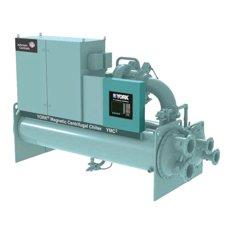
York OPTIVIEW Operation manual

York

York OPTIVIEW Operation manual

Flomatic Miniair installation instructions

Flomatic

Flomatic Miniair installation instructions

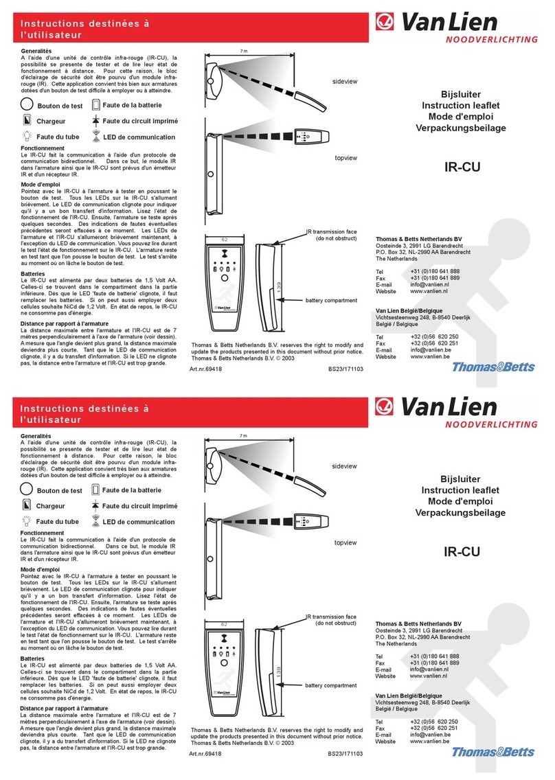
Van Lien IR-CU instruction manual

Van Lien

Van Lien IR-CU instruction manual

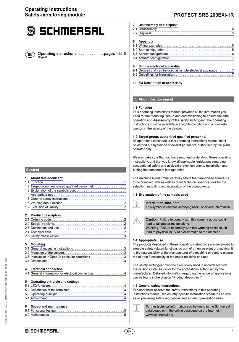
schmersal PROTECT SRB 200EXi-1R operating instructions

schmersal

schmersal PROTECT SRB 200EXi-1R operating instructions

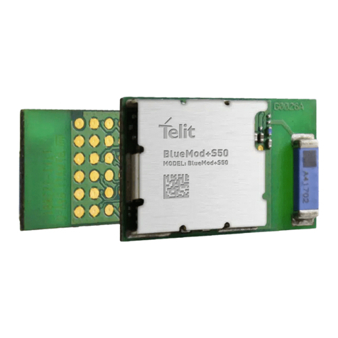
Telit Wireless Solutions BlueMod+S50/AI Hardware user's guide

Telit Wireless Solutions

Telit Wireless Solutions BlueMod+S50/AI Hardware user's guide

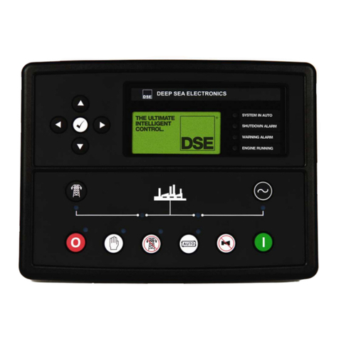
DSEGenset DSE7400 Operator's manual

DSEGenset

DSEGenset DSE7400 Operator's manual

Laird SDC-SSD30AG Hardware integration guide

Laird

Laird SDC-SSD30AG Hardware integration guide

Acuity Brands Lighting 5BPMW LED installation instructions

Acuity Brands Lighting

Acuity Brands Lighting 5BPMW LED installation instructions

Danfoss TS 12.5 installation guide

Danfoss

Danfoss TS 12.5 installation guide

SRA iPAMM installation manual

SRA

SRA iPAMM installation manual

Dungs VPM-VC instructions

Dungs

Dungs VPM-VC instructions

Harvia Sentiotec A2 Instructions for installation and use

Harvia

Harvia Sentiotec A2 Instructions for installation and use

Automated Logic InterOP8500 Technical instructions

Automated Logic

Automated Logic InterOP8500 Technical instructions

Exsys EX-1338HM user manual

Exsys

Exsys EX-1338HM user manual

ITR MUPASZ 710 plus user manual

ITR

ITR MUPASZ 710 plus user manual

Hayward SP0735 owner's manual

Hayward

Hayward SP0735 owner's manual

Emerson ASCO 290 Series Installation and maintenance instructions

Emerson

Emerson ASCO 290 Series Installation and maintenance instructions

Tech Controllers EU-L-X WiFi user manual

Tech Controllers

Tech Controllers EU-L-X WiFi user manual

manuals.online logo
manuals.online logoBrands
  • About & Mission
  • Contact us
  • Privacy Policy
  • Terms and Conditions

Copyright 2025 Manuals.Online. All Rights Reserved.