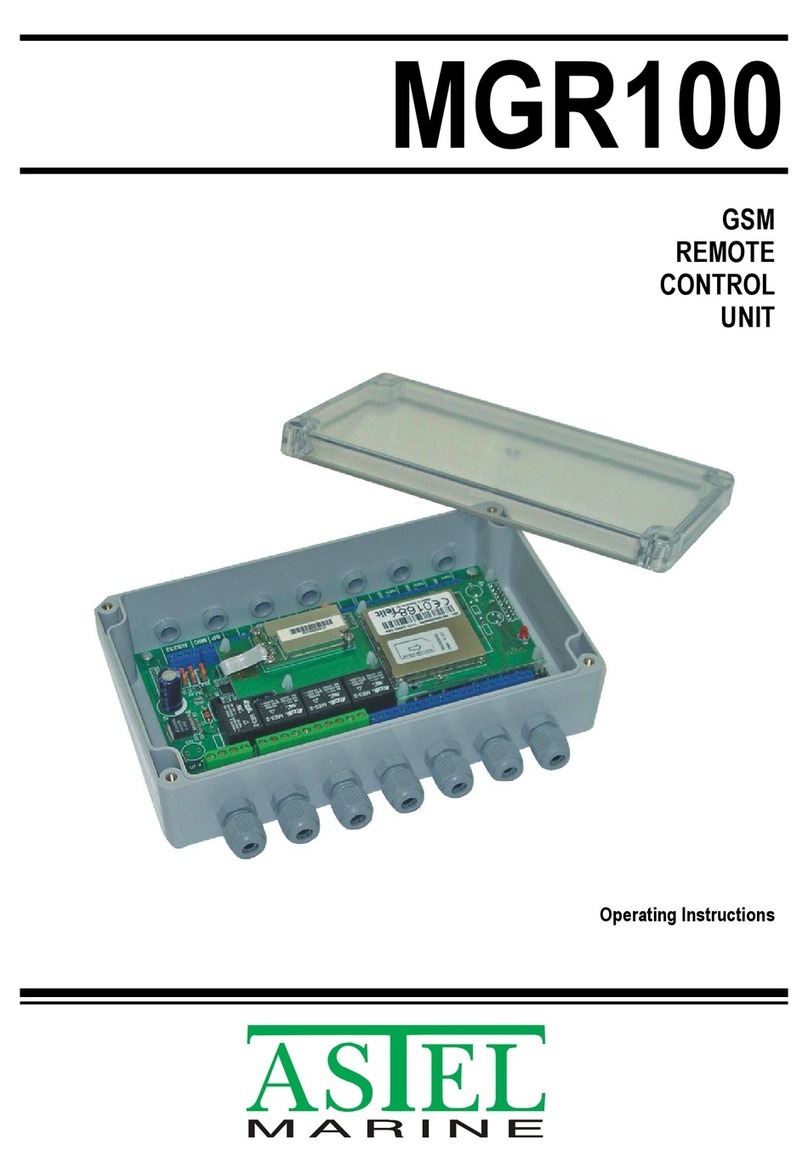
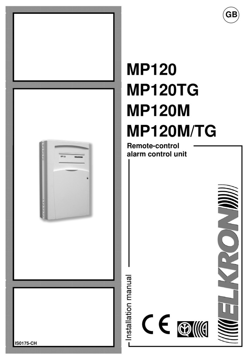
SRA iPAMM User manual

* Includes iPAMM Orientation Instructions
Congratulations on becoming the proud owner of an iPAMM, we believe you have
made the right choice and hope you will enjoy all of its capabilities. The iPAMM
provides outstanding performance in all criteria of server racks – energy efficiency,
reliability, security and price. This is achieved with a patented air management
system which has been engineered and manufactured entirely in Australia.
This document is subject to change without notice. We recommend obtaining the
latest version from the Server Racks Australia Website: www.srasolutions.com.au
IIf you have difficultly installing an iPAMM Unit please contact SRA for advice.
For iPAMM Version 2.0
Please Note -
The term iPAMM is used throught this
document and referes in the majority of cases
to the collective family of iPAMM Ready,
iPAMM and iPAMM Plus models.
Installation Manualv2.0
Intelligent Plenum Air Management Module
iPAMM
Version 2.0
v2.0

The iPAMM is provided for customers to assemble in their rack in order to minimise
the use of valuable RU space and to ensure it is possible to remove an iPAMM for
service. These instructions are intended to make installation an easy process.
If you have difficultly installing an iPAMM Unit please contact SRA for advice.
iPAMM Kit - A. iPAMM Unit (x1), B. iPAMM
Stud Plates (x2), C. iPAMM Mounting Rails
(x2), D. iPAMM Grille (x1)
Hardware - E. M6 x 16 Screws (x6),
F. M5 Flange Nut (x10), G. M5 Contact
Washer (x8), H. M5 Locating Washer (x4)
Email - enquiry@srasolutions.com.au
5.A Slide the iPAMM Main Body
into position holding the handle with
one hand, gently lower the iPAMM Main
Body into the front area of the rack with
the other hand supporting the pinchweld
side of the unit.
5.B Gently slide the bottom part of the
iPAMM Main Body closer to the Mounting
rails while keeping the pinch weld just
above the escutcheon plate of the rack
frame.
Ensure that the two rear Mounting Pins
are beneath the iPAMM Mounting Rails.
5.B Note the pins
6. Once the front of the iPAMM
can drop into the frame of the rack,
push the iPAMM back, ensuring that the
front two Mounting Pins slide under the
iPAMM Mounting Rails.
Once the iPAMM is placed up against the
Mounting Rails, use 2 x Flange Nuts and 2
x Contact Washers, over the third stud
from the bottom (position 3).
7. Slide the iPAMM Top Cover into the
channel. Secure using 2 x Flange Nuts
and 2 x Contact Washers, over the fourth
stud from the bottom (position 2).
8. Place the iPAMM Grille onto the
front of the unit with the return
towards the top. Place the pinch weld
side hard up against bottom of the
IPAMM and frame bottom, then pivot the
grille such that the top return slides
underneath the top cover. It may require
some downward pressure to locate the
lip under the top cover.
9. Secure the iPAMM Grille with 4 x
Flange Nuts and 4 x Contact Washers, on
the top (posiiton 1) and bottom studs
(position 5).
5.A Mount the unit
6 Use contact washers 7Fit the top cover
8Angle the grille 9Secure the grille
1. Install the iPAMM Mounting
Rails by placing the tabs through the
slots in the Rack Mount Arms as shown.
2. Secure the Mounting Rails to the Rack
Mount Arms using 3 x M6 Screws, repeat
the process with the remaining Mount
Rail on the opposing Mount Arm.
3. Place the Locating Washers
over studs 2 and 4 on both of the Stud
Plates.
Position the 2 x Stud Plates (with the
Locating Washers still in place) into the
front Mounting Rails of the Rack.
4. Secure the 2 x Stud Plates using a
Flange Nut on the 2nd stud (position 4)
from the bottom of each plate.
1Mount the rails 2Secure the rails
3 Locate the washers 4 Secure the plate
iPAMM
Installation Manual
Warning: Do not connect the iPAMM to any power source until the
unit is completely installed.
VERSION 2.0
iPAMM
Version 2.0
iPAMM
Version 2.0
Installation Manual
iPAMM Mounting Kit
Warning: Do not connect the iPAMM to any power source until the
unit is completely installed.
B.
C.
E.
F.
G.
H.
A. NOT SHOWN
D. NOT SHOWN
C.
H.
H.
H.
H.
B.
B.
C. + E.
1.
2.
3.
4.
5.
H. + F.
H.
1.
2.
3.
4.
5.
F. + G.
1.
2.
3.
4.
5.
F. + G.
v2.0 v2.0
1.
2.
3.
4.
5.
F. + G.

Installation Manual
iPAMM
Version 2.0 Warning: Do not connect the iPAMM to any power source until the
unit is completely installed.
10. If the Magnetic Blanking Sheet
is supplied, place over the exposed
venting immediately behind the iPamm
module.
11. Ensure all vents are covered by the
Magnetic Blanking Sheet as shown and
the sheet is up against the end of the
iPamm.
If this optional Magnetic Blanking Sheet is
not supplied please contact SRA Solutions
to discuss as sheet will increase iPAMM
performance.
11 Check placement10 Place the sheet
iPAMM installation is now complete
iPAMM
Versi
iPAMM installation is now complete
v2.0

The following information is an instructional process on how to alter the orientation
of an iPAMM unit from a ‘Bottom Mount’ to a ‘Top Mount’ model. Alternatively, these
instructions can be followed in reverse to alter orientation opposite to what’s shown.
If you have difficultly installing an iPAMM Unit please contact SRA for advice.
iPAMM Tools - A. PH2 Screwdriver (x1),
B. 2.5mm Allen Key Driver Bit (x1), C. Drill
Driver (x1)* - Image for reference only.
Hardware - Existing Hardware, including:
D. M4 x 12 Screws (x2),
E. M3 x 10 Pan Phillips Screw (x4)
Email - enquiry@srasolutions.com.au
5.Carefull rotate the iPAMM
Display PCB so that the 4 x indicating
lights are on now on the left hand side
(when facing from the front). Ensure
cable remains attached.
5. Rotate iPAMM PCB Display Plate so the
indicating numbers are now on the left
hand side (when facing from the front).
6 Rotate display plate
7. Place the iPAMM PCB Display
Plate into position by supporting the
iPAMM Display PCB and lining up the
screw holes.
Fasten using 4 x M3x10 Pan Phillips
Screws.
8. Place PCB Protective Cover into
position by supporting the iPAMM Circuit
Board Guard and lining up the screw
holes.
9. Resecure the Chrome Handle
by aligning the iPAMM Circuit Board
Guard holes and supporting both the
guard and handle.
Fasten using 2 x M4x12 Button Head
Socket Screws.
10. Slide on cover, your iPAMM can now
be installed as a top mount unit.
5 Rotate the PCB
7 Secure display plate 8Fasten PCB guard
9Fasten the handle 10 Slide on cover
1. Remove the iPAMM from the
server rack and place on a stable
surface sliding cover facing up.
Slide off cover to reveal the iPAMM
Display PCB.
2. Stand iPAMM on its end carefully to
reveal the iPAMM Circuit Board Guard.
Using the 2.5mm Allen Key, remove the 2
x M4x12 Button Head Socket Screws
holding the cover on.
3. Remove the Chrome Handle.
4. Using the PH2 Screwdriver, remove
the 4 x M3x10 Pan Phillips Screws holding
the iPAMM PCB Display Plate to the
iPAMM unit.
Note these screws also fasten the PCB to
the underside of the iPAMM unit.
Ensure the iPAMM Display PCB is fully
supported before removing the iPAMM
PCB Display Plate.
1Slide off cover 2Remove PCB guard
3 Remove the handle 4 Remove display plate
iPAMM Orientation
Warning: Do not attempt to modify the orientation of the iPAMM
PCB until it is removed from the rack and the power is isolated.
VERSION 2.0
iPAMM orientation is now complete
iPAMM
Version 2.0
iPAMM
Version 2.0
iPAMM Orientation
iPAMM Mounting Kit
Warning: Do not attempt to modify the orientation of the iPAMM
PCB until it is removed from the rack and the power is isolated.
D.
v2.0 v2.0
E.
D.
E.

