healing HDC6IRL User manual

healing HDC6IRL HDMI Extender - 50m (164ft) single CATx UTP HDMI
Extender with Transmitter loop through and wideband IR control.
User manual VER:1.4l
Thank you for purchasing. For optimum performance and safety
please read these instructions carefully before connecting, operating
or adjusting this product. Keep this manual for future reference.
1. Introduction
This HDMI Single Cat5e/6 Extender with IR extends High Definition
video, audio and IR control to a distance of up to 50metres (or 164ft)
over a single Cat5e or Cat6 cable. Features include EDID
management, which facilitates source and display 'handshake' for
seamless integration. With only one cost effective Cat5e/6 cable,
devices with HDMI outputs can be connected to High Definition
displays over long distances, without signal processing delays or
latency. Deep Colour video, DTS-HD or Dolby TrueHD audio are
compatible with the extender. HD6IRL is also equipped with a
wideband Infra Red control extender, which allows the source device
to be controlled from the remote display, up to 50m away. One
extender set includes Transmitter, Receiver IR Receiver, IR Blaster
and Power Supply. The transmitter processes the HDMI signal,
balancing it across the 4 pairs of the single CATx cable. IR commands
are simultaneously passed over the same cable from the Receiver to
the Transmitter. The Receiver reconstructs the HDMI signal from the
CATx cable, equalizes the level for cable length and makes the signal
ready for connection by HDMI to the remote display. The extender
provides a convenient long distance solution for HDMI extension over
a single Cat5e/6 cable, a perfect solution for PayTV or any HDMI
signal.

2. Package Contents:
HDMI Transmitter 1pc,
HDMI Receiver 1pc,
IR Tx cable-wideband 1pc,
IR Rx cable-wideband 1pc,
5V1A DC Power Supply 1pc,
Product User Manual 1pc
3. Features:
Sends HDMI Audio & Video with return wideband IR control signals
over a single Cat5e or Cat6 cable. Up to 1080p High Definition
resolution. Compact design installs easily. Electronic Display
IDentification (EDID) is selected for the REMote Receiver display or
LOCal Transmitter loop out display. HDMI Loop Out permits
simultaneous connection to a display near the Transmitter. Only one
5V Power Supply is required at the Transmitter, thanks to Power Over
Cable function. Transmission Range: Extends up to 50m or 164 ft of
single Cat5e or Cat6 cable for 1080p resolution. HDCP compliant.
4. Specifications:
Video Bandwidth: 4.95Gbps / 165MHz, Single-link
Video Resolutions: 1080p, 1080i, 720p, 480p, or 480i @50 or 60Hz
Audio: Surround Sound (up to 7.1 ch) or stereo digital audio
Transmission Range: distances up to 50metres or 164 ft, HD 1080p
24-bit colour
Input TMDS Signal: 3.3 volts
Input DDC Signal: 5.0 volts P-P
ESD Protection: Human Body model: ±8 kV (air-gap discharge) ±4 kV
(contact discharge)
HDMI connectors: Type A 19 pin female
RJ-45 connectors: WE/SS 8P8C
3.5mm connectors: (Tx) for IR Blaster and (Rx) for IR Receiver

Mechanical Specifications:
Housings: Precision stamped metal thread screw secured steel
enclosures
Power Supply: 1 x 5V DC 1A
Power consumption: 1.5 watts (TX); 1.0 watts (RX)
Operating temperature: 0 to 40°C Storage temperature -20 to 60°C
Relative humidity 20 to 90 % RH (no condensation)
5. Panel descriptions
5.1 Transmitting unit
1. HDMI In: Here you connect the HDMI output from your
source equipment, Set Top Box, BluRay, CCTV NVR etc. HDMI
cable excluded.
2. EDID: Selects Electronic Display IDentification from one of the
HDMI outputs. Switch to LOCal or right, to pass HDMI loop
out display EDID. Switch to REMote or left position to pass
Receiver display EDID to source device.
3. HDMI out: Connect to HDMI input of local TV or display,
HDMI cable excluded.
4. IR out: Connect the IR Blaster or Emitter included in the set
for IR signal re-transmission. Place the IR blaster where it has
best line-of-sight view the front of the equipment to be
controlled. The Blaster's adhesive pad may assist fixing in a
convenient position. As the adhesive is single use, you may
wish to test first.
5. Power LED: Illuminates when the device is connected to 5V
DC power.
6. CATx: Connect the Transmitter output to the Receiver input
with CAT5E/6 cable. Better quality cable may permit you to
reach 60m distance.
7. Link LED: Illuminates when the Transmitter is connected to
HDMI a source.
8. DC 5V: Connect power supply included to Transmitter.
Connect to mains after Receiver and monitor(s) are
connected. Under no circumstances should voltage higher
than 5V be connected.
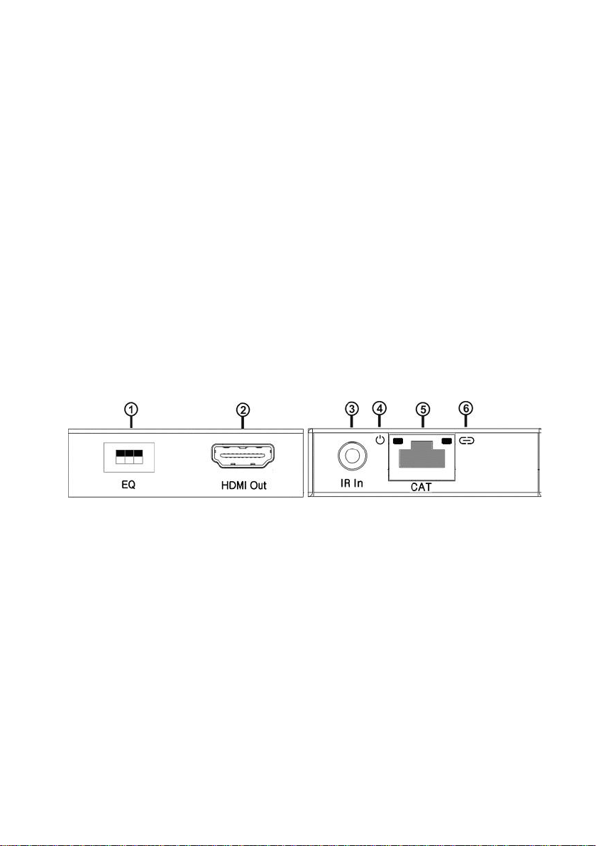
5.2 Receiver unit
1. EQ switch: CATx cable length equalizer, set according to point
5.3 (below).
2. HDMI out: Connects to remote display or TV HDMI input,
HDMI cable excluded.
3. IR in: Connect the (larger) IR Receiver. Ensure remote control
and receiver in direct line-of-sight.
4. Power LED: glows when the receiver connected to the
transmitter's Power Over Cable supply.
5. CATx: Connect the Receiver input to the Transmitter output
with CAT5E/6 cable.
6. Lock LED: Illuminates when the HDMI signal from the
transmitter is stable.
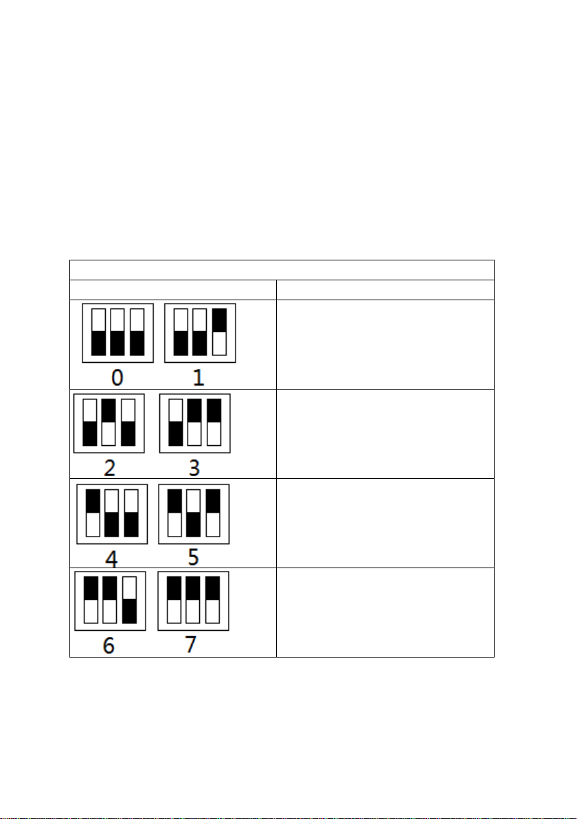
6. RX Equalizer adjustment for CATx distance
Flickering or blinking images on the remote display usually means the
EQ cable skew switch needs to be set. 7 is for the longest possible
CATx transmission cable length (HDMI signal level is the strongest),
whilst 0 is for the shortest CATx transmission cable length (HDMI
signal level is the weakest). Adjust equalization from 0 through 7
until reliable video quality can be seen on the far monitor.
Recommended EQ settings
Recommended EQ setting
Position
Cable Length
under 15m (49.5ft)
15 to 30m (49.5 ft to 99ft)
30 to 40m (99ft to 132ft)
40 to 50m(132ft to 164ft)

7. Connection diagram:

8. HDMI Extension Connection and Operation
1. Plug your chosen HDMI source such as a Set Top Box, Blu-Ray
Player, game console, A/V Receiver etc. to the HDMI input on
the Transmitting unit - via a HDMI cable (excluded).
2. Connect the TV, HD display or Projector to the HDMI output
on the Receiving unit - also via a HDMI cable (excluded).
3. Plug a single Cat6 etc. cable (up to 50m or 164ft long) to the
CATx output of the Transmitting unit, and the other end to
the CATx input of the Receiver.
4. To power, connect the 5V DC supply to the Transmitter.
Receiver is Powered Over Cable.
5. At this point the display connected to the Receiver should
show the source signal connected to the Transmitter.
Should the video be unstable, check the Equalization setting
point 6meets your CATx cable length. Try some close but
different settings. If one display is having difficulty resolving,
try changing the EDID switch (you may need to power cycle
for this to take effect) or adjust the display's resolution by it's
menu from lowest to highest until picture displays. A 24Hz
vertical refresh rate may work better than 60Hz or higher.

9. Infra Red Command Repeater Connection and Operation
IR BLASTER (IR Out)
Plug IR Blaster 3.5mm plug into the IR Out port of Transmitter unit.
Place the IR Blaster in front of the source device's IR receiver, usually
in the front panel.
IR RECEIVER (IR In)
Plug IR Receiver 3.5mm plug into the IR In port of Receiver unit.
Place IR Receiver at or near the remote display, so the front has the
clearest line of sight view of the area from which the remote control
might be used.
If the IR remote function is not responding, Ensure the IR Receiver
and Blaster are fully inserted into the correct IR jacks on the Extender
and Transmitter units, and are not reversed. Carefully place the IR
Receiver and IR Blaster for best operation.
Check there are no obstacles between your remote and IR
Receiver, or IR Blaster and device.
A smart phone camera can help by showing the IR blaster
output.
Ambient infrared light from windows or some lighting can
reduce IR remote control range, so it may be necessary to shield
the IR Receiver or position IR Blaster more carefully in
consideration.
©2017 online.laceys.tv
Table of contents
Other healing Extender manuals


