manuals.online logo
Brands
  1. Home
  2. •
  3. Brands
  4. •
  5. Savant
  6. •
  7. Extender
  8. •
  9. Savant PAV-VIMVP1F2 Series User manual

Savant PAV-VIMVP1F2 Series User manual

PAV-VIMVP1F2-xx/PAV-VIMVP1CP2-xx QRG | 009-2059-00
Copyright 2022 Savant Systems, Inc | 220121
45 Perseverance Way, Hyannis, MA 02601
Savant.com | 508.683.2500
1 of 2
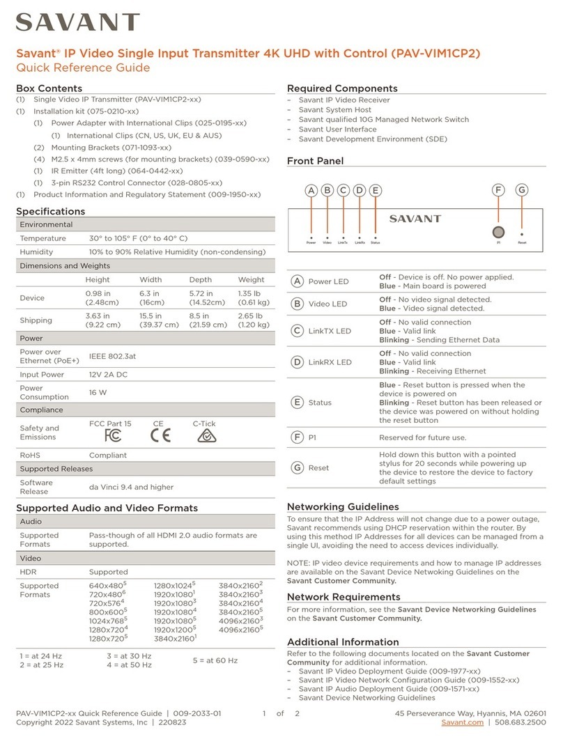
Box Contents
(1) IP Video Transmitter (PAV-VIMVP1F2-xx/PAV-VIMVP1CP2-xx)
(1) SFP+ module (PAV-VIMVP1F2-xx only)
(1) Installation Kit (075-0210-xx)
(1) Power Adapter with International Clips (025-0195-xx)
(1) International Clips (CN, US, UK, EU & AUS)
(2) Mounting Brackets (071-1093-xx)
(4) M2.5 x 4mm screws (for mounting brackets) (039-0590-xx)
(1) IR Emitter (4ft long) (064-0442-xx)
(1) 3-pin RS232 Control Connector (028-0805-xx)
(1) Product Regulatory Statement (009-1950-xx)
Required Components
–Savant IP Video Receiver
–Savant System Host
–Savant qualified 10G Managed Network Switch
–Savant User Interface
–Savant Development Environment (SDE) and Configuration Tools
Compliance
Safety and
Emissions
FCC Part 15 CE C-Tick UKCA
RoHS Compliant
Power
Input Power 12V 3A DC
PoE+ (IEEE 802.3at)
Nominal Power 16 W (PAV-VIMVP1F2-xx)
19 W (PAV-VIMVP1CP2-xx)
Maximum Power 36 W (PAV-VIMVP1F2-xx)
36 W (PAV-VIMVP1CP2-xx)
Dimensions and Weights
Height Width Depth Weight
Device 0.98 in
(2.50 cm)
8.46 in
(21.50 cm)
5.51 in
(13.99 cm)
1.65lb
(0.75 kg)
Shipping 4.0 in
(10.16 cm)
9.0 in
(22.86 cm)
16.0 in
(40.64 cm)
4.8lb
(2.17 kg)
Rack Space 1U
Environmental
Temperature 32° to 104° F (0° to 40° C)
Humidity 10% to 90% Relative Humidity (non-condensing)
Specifications
Supported Releases
Software Release da Vinci 9.4.3and higher
Front Panel
Additional Information
Refer to the following documents located on the Savant Customer
Community for additional information.
– Savant IP Video Deployment Guide (009-1977-xx)
– Savant IP Video Network Configuration Guide (009-1552-xx)
– Savant IP Audio Deployment Guide (009-1571-xx)
–Savant Device Networking Guidelines
System
G
USB HOST
H I
P1
J
USB HID
Video
C
LinkTx
D
USB
F
LinkRx
E
Status
B
Power
A
Item Description
Power LED O - Device is o. No power applied.
Red - Main board is powered.
Status LED
Blue - Reset button is pressed when the
device is powered on.
Blinking - Reset button has been released or
the device was powered on without holding
the reset button.
Video LED O - No video signal detected.
Blue - Video signal detected.
Link TX LED
O -No valid connection
Blue - Valid link
Blinking - Sending Ethernet Data
Link RX LED
O - No valid connection
Blue - Valid link
Blinking - Receiving Ethernet Data
USB Reserved for future use.
System LED Not used and will remain in the OFF state.
H
USB Host Reserved for future use.
IUSB HID Reserved for future use.
JP1 Reserved for future use.
A
B
C
D
E
F
G
Audio
Supported
Formats
Pass-though of all HDMI audio formats are
supported.
Video
HDR Supported
Dolby® Vision Supported
Supported
Formats
640x48051280x72041920x108043840x21603
720x48051280x72051920x108053840x21604
720x57641280x102451920x120053840x21605
800x60051920x108013840x216014096x21603
1024X76851920x108033840x216024096x21605
1 = at 24 Hz
2 = at 25 Hz
3 = at 30 Hz
4 = at 50 Hz 5 = at 60 Hz
Supported Audio and Video Formats
Networking Guidelines
To ensure that the IP Address will not change due to a power outage,
Savant recommends using DHCP reservation within the router. By
using this method IP Addresses for all devices can be managed from a
single UI, avoiding the need to access devices individually.
NOTE: IP video device requirements and how to manage IP address-
es are available on the Savant Device Netwoking Guidelines on the
Savant Customer Community.
Savant® IP Video Single Input Transmitter 4K UHD with Video Processing and Control
(PAV-VIMVP1F2/PAV-VIMVP1CP2)
Quick Reference Guide
PAV-VIMVP1F2-xx/PAV-VIMVP1CP2-xx QRG | 009-2059-00
Copyright 2022 Savant Systems, Inc | 220121
45 Perseverance Way, Hyannis, MA 02601
Savant.com | 508.683.2500
2 of 2
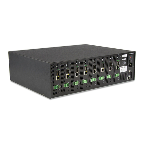
Rear Panel Wiring and Connections
IR connection is made using 3.5 mm IR Emit-
ter supplied with the device.
IR Wiring
Enhanced small form-factor pluggable connection. Duplex LC
Multi-mode OM3 Fiber required.
Transport Distance
DAC cable 6ft (2m)
OM3 multi-mode fiber 1000ft (300m)
Optical In (PAV-VIMVP1F2-xx)
RJ-45 10G Ethernet connection.
Transport Distance
Cat6 100ft (30m)
Cat6a 300ft (100m)
Cat7 300ft (100m)
10 GbE (PAV-VIMVP1CP2-xx)
PAV-VIMVP1CP2-xx
DC 12V IR OutIR In
A B C
HDMI In
D
Loop Out
E
RS232
TX RX G
F
10 GbE (PoE+)
G
Audio LAN
K
RESET
H
I
L
M
JN
Item Description
APower Input 12V DC
BIR In Not used
CIR Out
3.5 mm IR Emitter connection. Transmits IR
signals via an IR Flasher (5V tolerant) to devices
with an IR input or IR receiver.
DHDMI In
19-Pin Type A HDMI female digital audio/video
input.
Supports HDMI 2.0a
HDMI 2.0 compliant cable required for 4K
content.
ELoop Out Reserved for future use.
FRS-232
3-pin control connector transmits and receives
serial data to and from serial controllable
devices. For pin-out information, refer to the
RS-232 Wiring section to the right.
G10 GbE
10G input from the Audio/Video over IP switch.
SFP+ (PAV-VIMVP1F2-xx)
RJ-45 (PAV-VIMVP1CP2-xx) supports Power
over Ethernet (PoE+ IEEE 802.3at standard).
HLink LED
Solid Green - Link is established with
2.5/5GBase-T mode.
Solid Amber - Link is established with
10GBase-T mode.
O – No link established.
ILink Activity
LED
Amber Blinking - Indicates data activity.
O – No Activity.
JAudio
3.5 mm (1/8 in) Analog Audio Output.
Outputs 2 Ch PCM audio from the local HDMI
input when 2 CH and MC PCM is present. Does
not support downmixing encoded audio.
Direct Line Level 2.1 VRMS Output.
KLAN
1G of reserved network data bandwidth
commonly used to connect any network
compliant device to transmit its data onto the
Ethernet network by sharing the 10G network
link. 8-pin RJ-45 female connection.
IMPORTANT!: Do not connect this port to a
network switch.
LLink LED Solid Orange - Link is established.
O – No link established.
MLink Activity
LED
Amber Blinking - Indicates data activity.
O – No Activity.
NReset
Hold down this button with a pointed
stylus for 20 seconds while powering up
the device to restore the device to factory
default settings.
Rear Panel
Power Input
Serial control connection are made
using a 3-pin Control Connector
supplied with the device. The wire slips
into the hole and locks with a screw
located at the top of the connector.
RS-232 Wiring
3
2
1
Rx
Tx
G
PIN 1
PIN 2
PIN 3
Receive
Transmit
Ground
Installation
To install this device use the mounting screws to attach the
included mounting brackets. Please follow the steps below.
1. Align the bracket using the top holes.
NOTE: This will leave an air gap behind the device.
2. Use mounting screws to attaching the bracket.
If the device is going to be mounted Savant recommends aligning the
device with the rear of the device facing down. This will allow the best
heat dissipation.

This manual suits for next models

2

Other Savant Extender manuals

Savant BLASTER User manual

Savant

Savant BLASTER User manual

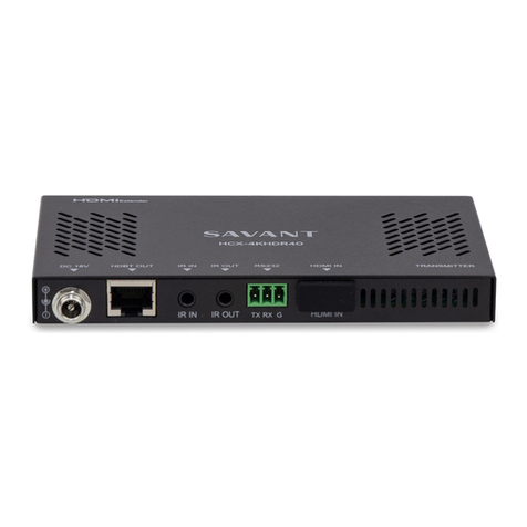
Savant HCX-4KHDR40 User manual

Savant

Savant HCX-4KHDR40 User manual

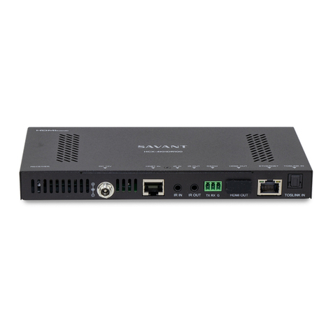
Savant HCX-4KHDR100 User manual

Savant

Savant HCX-4KHDR100 User manual

Savant HCX-1100 User manual

Savant

Savant HCX-1100 User manual

Savant HCX-1010 User manual

Savant

Savant HCX-1010 User manual

Savant PAV-VIMAP8S Quick reference guide

Savant

Savant PAV-VIMAP8S Quick reference guide

Savant HCX-4KHDR40 User manual

Savant

Savant HCX-4KHDR40 User manual

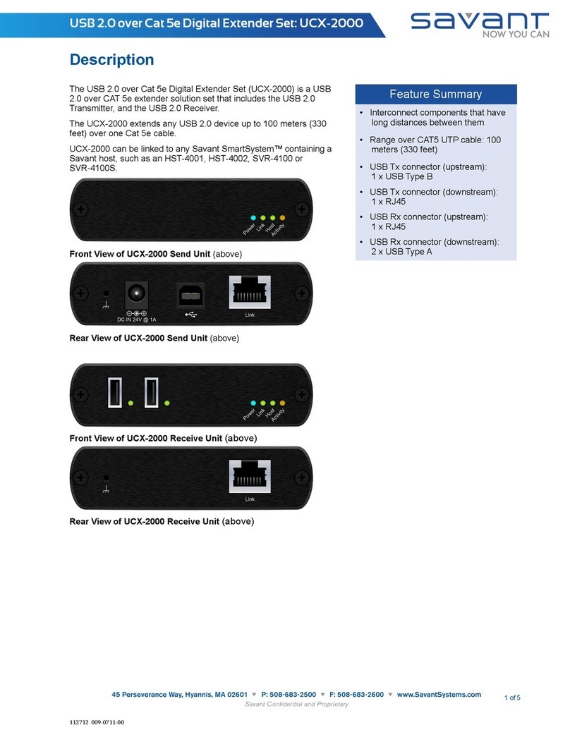
Savant UCX-2000 User manual

Savant

Savant UCX-2000 User manual

Savant HCX-4KHDR100 User manual

Savant

Savant HCX-4KHDR100 User manual

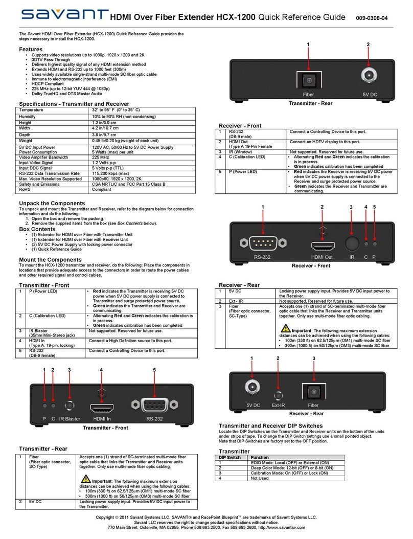
Savant HCX-1200 User manual

Savant

Savant HCX-1200 User manual

Savant HCX-4KHDR100 User manual

Savant

Savant HCX-4KHDR100 User manual

Savant PAV-VIM1CP2 Series User manual

Savant

Savant PAV-VIM1CP2 Series User manual

Popular Extender manuals by other brands

fios Home Wi-Fi Extender installation instructions

fios

fios Home Wi-Fi Extender installation instructions

Powerfix Profi 270224 Operation and safety notes

Powerfix Profi

Powerfix Profi 270224 Operation and safety notes

TP-Link RE190 user guide

TP-Link

TP-Link RE190 user guide

TP-Link WPA8630PK user guide

TP-Link

TP-Link WPA8630PK user guide

Magma ExpressBox EB1F user manual

Magma

Magma ExpressBox EB1F user manual

Wi-Ex zBoost YX520 user guide

Wi-Ex

Wi-Ex zBoost YX520 user guide

LevelOne WRE-6001 Quick installation guide

LevelOne

LevelOne WRE-6001 Quick installation guide

Sitecom WLX-1000 installation guide

Sitecom

Sitecom WLX-1000 installation guide

Alto Professional Stealth Wireless user guide

Alto Professional

Alto Professional Stealth Wireless user guide

Lightware VINX-110-HDMI-DEC quick start guide

Lightware

Lightware VINX-110-HDMI-DEC quick start guide

gofanco HDwireless100-LT user guide

gofanco

gofanco HDwireless100-LT user guide

Gefen ex-tend-it DVI Detective user manual

Gefen

Gefen ex-tend-it DVI Detective user manual

StarTech.com 8STST121HDBT20S manual

StarTech.com

StarTech.com 8STST121HDBT20S manual

Sitecom WL-130 manual 

Sitecom

Sitecom WL-130 manual 

TP-Link TL-WPA4220 TKIT Quick installation guide

TP-Link

TP-Link TL-WPA4220 TKIT Quick installation guide

COMEXIO Extension-Amp manual

COMEXIO

COMEXIO Extension-Amp manual

Ihse K450-1S Installation and operation manual

Ihse

Ihse K450-1S Installation and operation manual

zBoost SOHO YX545 user guide

zBoost

zBoost SOHO YX545 user guide

manuals.online logo
manuals.online logoBrands
  • About & Mission
  • Contact us
  • Privacy Policy
  • Terms and Conditions

Copyright 2025 Manuals.Online. All Rights Reserved.