Health GEAR SleepZone C2 User manual

UserManual MK/YF38-07–V2.01CS
©2019AllRightsReserved
Pa
g
e 1 of 60
User Manual
Sleep Apnea Therapy Devices
Models: C2 (CPAP) & C5 (AUTO CPAP)

UserManual MK/YF38-07–V2.01CS
©2019AllRightsReserved
Pa
g
e 2 of 60
(This page intentionally left blank)

UserManual MK/YF38-07–V2.01CS
©2019AllRightsReserved
Pa
g
e 3 of 60
Contents
PREFACE.................................................................................................................................6
CHAPTER 1 PRODUCT OVERVIEW.....................................................................................7
1.1
I
NTENDED PURPOSE
,
PRODUCT USAGE AND APPLICATION
....................................................7
1.2
W
ORKING PRINCIPLE
............................................................................................................8
1.3
S
AFETY TIPS
.........................................................................................................................8
1.3.1
W
ARNING
...................................................................................................................................8
1.3.2
C
AUTIONS
................................................................................................................................10
1.3.3
C
ONTRAINDICATIONS
..............................................................................................................11
1.3.4
P
OTENTIAL SIDE EFFECTS AND SOLUTIONS
...........................................................................12
CHAPTER 2 APPEARANCE AND ACCESSORIES...........................................................13
2.1
A
BOUT THE MODEL
.............................................................................................................13
2.2
C
OMPONENT SUMMARY
......................................................................................................13
2.3
C
OMPONENTS AND PARTS
..................................................................................................14
2.4
N
OTES ABOUT TERMINOLOGIES AND ACRONYMS
................................................................16
2.5
A
BOUT THE SIGNS
..............................................................................................................16
CHAPTER 3 INSTALLATION AND OPERATION................................................................18
3.1
P
LACEMENT LOCATION
.......................................................................................................18
3.2
S
ET UP
...............................................................................................................................18
3.2.1
P
RE
-
ASSEMBLY PREPARATION
................................................................................................18
3.2.2
C
ONNECT POWER TO THE
M
ACHINE
......................................................................................18
3.2.3
C
ONNECT THE HOSE TO THE MASK
........................................................................................19
3.2.4
F
ILL THE WATER TANK
.............................................................................................................19
3.2.5
C
ONNECT THE HOSE TO THE
M
ACHINE
..................................................................................21

UserManual MK/YF38-07–V2.01CS
©2019AllRightsReserved
Pa
g
e 4 of 60
CHAPTER 4 EQUIPMENT USE............................................................................................22
4.1
P
RE
-
START INSPECTION
-
M
ACHINE
....................................................................................22
4.2
P
RE
-
START INSPECTION
-
M
ASK
.........................................................................................22
4.3
S
TARTING TREATMENT
.......................................................................................................23
4.4
S
TOPPING TREATMENT
.......................................................................................................23
4.5
P
ATIENT AND CLINICIAN MODES
..........................................................................................24
4.6
P
ATIENT MODE
...................................................................................................................24
4.6.1
E
NTER PATIENT MODE
.............................................................................................................24
4.6.2
P
ATIENT MENU
.........................................................................................................................24
4.7
C
LINICIAN MODE
.................................................................................................................29
4.7.1
E
NTER CLINICIAN MODE
..........................................................................................................29
4.7.2
R
ETURN TO PATIENT MODE
.....................................................................................................29
4.7.3
C
LINICIAN MENU
......................................................................................................................29
4.8
T
REATMENT SETTING PARAMETERS
....................................................................................30
4.9
D
ATA OUTPUT
.....................................................................................................................34
CHAPTER 5 HEATING HUMIDIFIER...................................................................................35
5.1
I
NTENDED USE
....................................................................................................................35
5.2
S
PECIFICATIONS
.................................................................................................................35
CHAPTER 6 WIFI...................................................................................................................37
6.1
E
XPECTED USAGE
..............................................................................................................37
CHAPTER 7 ALERTS............................................................................................................38
7.1
V
ISUAL AND
A
UDIBLE
A
LERTS
...........................................................................................38
7.2
A
LERT MESSAGES
..............................................................................................................38
7.3
A
LERT
S
USPENSION
...........................................................................................................40
CHAPTER 8 EQUIPMENT CLEANING AND MAINTENANCE..........................................41

UserManual MK/YF38-07–V2.01CS
©2019AllRightsReserved
Pa
g
e 5 of 60
8.1
R
EPAIR AND MAINTENANCE
................................................................................................41
8.2
F
REQUENCY
.......................................................................................................................41
8.3
C
LEANING METHOD
............................................................................................................41
8.3.1
C
LEANING OF
CPAP
MACHINE AND HOSE
.............................................................................41
8.3.2
W
ATER TANK CLEANING
..........................................................................................................42
8.3.3
A
IR FILTER CLEANING AND REPLACEMENT
.............................................................................42
CHAPTER 9 STORAGE AND TRANSPORTATION............................................................45
CHAPTER 10 TROUBLESHOOTING...................................................................................46
CHAPTER 11 TECHNICAL INFORMATION........................................................................49
11.1
P
ARAMETERS
...................................................................................................................49
11.1.1
D
EFAULT
C2
CPAP
M
ACHINE
S
ETTINGS
.............................................................................49
11.1.2
D
EFAULT
C5
A
UTO
CPAP
M
ACHINE
S
ETTINGS
..................................................................49
11.1.3
AC
A
DAPTER PARAMETERS
..................................................................................................50
11.1.4
M
ACHINE AMBIENT PARAMETERS
.........................................................................................50
11.1.5
P
HYSICAL AND ELECTRICAL PARAMETERS
...........................................................................50
11.1.6
E
LECTRIC SAFETY CLASS
.....................................................................................................51
11.2
P
NEUMATIC SCHEMATIC DIAGRAM
....................................................................................52
11.3
EMC
INFORMATION
..........................................................................................................52
11.3.1
I
NSTRUCTIONS FOR USE
.......................................................................................................52
11.3.2
T
ECHNICAL DESCRIPTION
.....................................................................................................53
11.3.3
RF
INFORMATION
..................................................................................................................57
APPENDIX 1: MODEL COMPARISON TABLE...................................................................58
APPENDIX 2: WARRANTY AND DOWNLOADS................................................................59

UserManual MK/YF38-07–V2.01CS
©2019AllRightsReserved
Pa
g
e 6 of 60
Preface
is a registered trademark of CPAP Sales Pty Ltd (hereinafter CPAP
Sales)
Models C2 (CPAP) and C5 (AUTO) are Sleep Apnea Therapy Devices (Non-invasive
ventilators) have been independently developed by Micomme Medical Technology
Development Co., Ltd (hereinafter referred to as Micomme Medical) exclusively for CPAP
Sales.
Micomme Medical reserves all the rights to information contained in the document. Unless
specially authorized by Micomme Medical in written form, nobody can copy any part of the
document in any way or save it into any electronic information retrieval system. No unit,
corporation or individual shall produce, sell or copy our products without being authorized by
our company; or it shall be deemed as an infringement of our protected patents, and our
company reserves the right to take any legal action against such infringement.
No additional notice shall be provided in case of any change in the information contained in
this document. Micomme Medical reserves the right to change equipment design,
performance, components and processes including any other circumstances to continually
improve product and quality assurance.

UserManual MK/YF38-07–V2.01CS
©2019AllRightsReserved
Pa
g
e 7 of 60
Chapter 1 Product overview
1.1 Intended purpose, product usage and application
This Class IIa Medical Device has been registered and approved by the Australian Therapeutic
Goods Administration (TGA) for supply by CPAP Sales Pty Ltd.
It is a portable, mains electricity (AC-powered) device, which may include rechargeable
batteries, intended to assist noninvasive ventilation (i.e., without use of an artificial airway)
using continuous positive airway pressure (CPAP) during spontaneous respiration, primarily to
treat adult patients affected by obstructive sleep apnea (OSA); it may also be intended to treat
snoring. It is a small desktop unit with controls, and may include a built-in humidifier; the airway
pressure may be automatically adjusted to help provide optimal CPAP through use of a sensor
(auto CPAP). The device is intended for use in the home but may also be used in healthcare
facilities.
Models C2 (CPAP) and C5 (AUTO) are Obstructive Sleep Apnea Therapy Devices (hereinafter
referred to as a “CPAP Machine”) providing non-invasive ventilation treatment for patients with
obstructive sleep apnea syndrome (OSAS). These CPAP Machines are for use by pediatric
patients aged over 7 (with a weight being over 18.1kg or 40lbs) and adult patients (with a
weight being over 30kg and 66lbs) only.
This CPAP Machine should be used by patients under the guidance of professionally trained
medical staff, with patient as the intended end user/operator. Patients with severe respiratory
failure but spontaneous breath should not use a CPAP Machine unless instructed to do so by a
medically trained professional.
CPAP Machines need to be used together with a breathing hose and a nasal/face mask
suitable to the patient.
To download this User Manual, please visit: cpapsales.com.au/manuals

UserManual MK/YF38-07–V2.01CS
©2019AllRightsReserved
Pa
g
e 8 of 60
1.2 Working principle
This CPAP Machine includes a power cord, ac adaptor, hose and Machine (including main
control panel, motor, display, control dial, buzzer, enclosure, humidifier, water tank and ozone
generator). Room air passes through a filter, and is sent out at a preset pressure and flow rate
through the controlled motor and heated humidifier, before reaching the respiratory tract and
finally the patient’s lungs. The CPAP Machine’s system can collect information about the
patient’s compliance use and Machine operating performance.
1.3 Safety tips
Warnings, cautions and notes apply to the whole User Manual.
1.3.1 Warning
The User Manual is for reference only. The description in it can’t substitute the
guidance of professional medical staff.
Before using the equipment, please read through and understand the User Manual.
The equipment is not designed to meet your complete ventilation demand or to be
used as life support system.
Since there is no circuit of expiration in the Ventilator, the user should be provided with
a face mask with at least 30LPM air-leaking holes to avoid repeated inhalation of the
carbon dioxide resulting from the breath.
The treatment parameters must be adjusted by trained professional medical staff.
In case of any discomfort in the equipment use, please immediately contact your
professional medical staff.
Use only the expiration circuit provided by your professional medical staff instead of
any anti-static or conductive hose or conduit.
Winding due to cables and breathing hoses, particularly due to excessive length.
Do not bend or wrap the breathing line during use.
When using the breath circuit integrated with expiration holes mask or circuit with
independent outlet device, do not bind or seal the air leaking holes, or block the fresh
air inlet with adhesive tape, seal or other substances, for it may stop the inspiration of
fresh air and even lead to suffocation.
When the equipment is working, do not cover it with any article, or else the fresh air

UserManual MK/YF38-07–V2.01CS
©2019AllRightsReserved
Pa
g
e 9 of 60
inlet may be blocked so that the user may get suffocated.
Do not try to wear the face mask before the equipment is turned on and works
normally; or repeated inspiration of carbon dioxide may be caused. In some case,
inspiration of exhaled gas for a few minutes can lead to suffocation.
In order to ensure normal use, the power supply must be inserted into the socket in a
vertical way.
Do not use this equipment alone for pediatric patients over 7 years old.
Please keep the equipment away from children and pets.
Against servicing and maintenance while the equipment is in use.
Regularly check if there is any damage or wearing sign in the electric wire, cable or
power supply device; if there is any, please stop using the device and arrange a
replacement.
The plug is used as disconnect device to the mains supply, do not to position the ME
EQUIPMENT so that it is difficult to operate the disconnection device.
To avoid electric shock, please disconnect the plug before cleaning the equipment.
The equipment maintenance and repair can only be done by the professional
repairman authorized by Micomme Medical.
No modification of this equipment is allowed.
Do not use the equipment when the room temperature is above 35℃, for the
temperature of the air flow in such case may exceed 43℃, and stimulus or damage
may be caused to your air passage.
Keep the equipment from sunshine or heating device when using it, for the air
discharged from the equipment in such case may have an elevated temperature.
Before using the equipment, please check if the present warning SET is suitable for
the patient. Improper warning preset in different areas may bring damage to the
patient.
When using the equipment, please prepare simple respirator or other Machine that
can substitute the equipment for the time being so that the normal treatment of patient
will not be interrupted and no damage is caused to the patient in case of sudden
failure with the equipment.
When noticing an unexplainable change or abnormal or annoying noise with the
working equipment,
If necessary, our company (Micomme Medical) may provide the technical files (e.g.
circuit diagram, list of elements, legends, and detailed rules and regulations about
calibration) required for the purpose of repair for the qualified technical maintenance
and repair staff either designed by us or of other types.

UserManual MK/YF38-07–V2.01CS
©2019AllRightsReserved
Pa
g
e 10 of 60
The product must be used as specified in IEC 60601-1:2005+A1:2012 Medical
electrical equipment - Part 1: General requirements for basic safety and essential
performance.
Additional equipment connected to medical electrical equipment through the
network/data coupling must comply with the respective IEC or ISO standards (e.g. IEC
60950 for data processing equipment). Furthermore all configurations shall comply
with the requirements for medical electrical systems (see IEC 60601-1-1 or clause 16
of the 3Ed. of IEC 60601-1, respectively).
Anybody connecting additional equipment to medical electrical equipment
configurations a medical system and is therefore responsible that the system complies
with the requirements for medical electrical systems. Attention is drawn to the fact that
local laws take priority over the above mentioned requirements. If in doubt, consult
your local representative or the technical service department.
Sources of oxygen must be located more than 1 m from the equipment to avoid the
risk of fire and burns.
1.3.2 Cautions
The equipment can only be operated in the ambient environment of 5℃-35℃.
To assure normal working, an undamaged reusable sponge filter should be properly
fixed at the air inlet.
The equipment should not be immersed in any liquid, and no liquid is allowed to enter
into its enclosure or inlet filter.
Condensation may damage the equipment. Please raise the equipment temperature to
the room temperature before using it.
Do not cover the equipment with such objects as blanket; or the fresh air intake may
be blocked so that the Machine become overheated to affect the treatment or damage
the equipment.
The equipment isn’t provided with power-off alert or power-off-resistant design. Within
it, there is no battery supply. Therefore, during the use, please ensure the adapter
power plug and equipment are properly connected, the power line is reasonably
placed in order to prevent the power plug from falling off from the equipment under
external force and consequent patient suffocation with harder respiration.
In case of recovery of power supply after an interruption, the equipment should be
restarted in treatment in order to assure normal working.
The waste and residue generated by the equipment as well as the expiry equipment
and its accessories should be classified before treatment so as to prevent
environmental pollution or other hazards.
The pressure sensor of the equipment remains as a key pressure test device, so it

UserManual MK/YF38-07–V2.01CS
©2019AllRightsReserved
Pa
g
e 11 of 60
should be sent to the maintenance staff passing the training organized by Micomme
Medical for maintenance every half a year; or the accuracy of the equipment’s
pressure output may be affected.
All the parameters of the ventilator are stored in non-volatile memory, so disconnection
of equipment with mains will not affect the SET of all such parameters.
Replacement of parts shall be made by the parts specified by the manufacturer of the
equipment and by the maintenance personnel designated by the manufacturer.
1.3.3 Contraindications
When having severe respiratory failure and no spontaneous breath, please do not use the
equipment.
When any of following situations applies to you, please consult professional medical staff
before using the equipment;
Insufficient respiratory drive to tolerate the intermittence of non-invasive ventilation
treatment;
Acute sinusitis and otitis media;
Some diseases that may cause intake of stomach contents;
Inability to clear the secretion;
Hypotension or apparent hypovolemia within blood vessel;
Pneumothorax or mediastinal emphysema;
Craniocerebral trauma or surgery;
receiving airway neostomy in the past;
Pulmonary bulla.

UserManual MK/YF38-07–V2.01CS
©2019AllRightsReserved
Pa
g
e 12 of 60
1.3.4 Potential side effects and solutions
The non-invasive PAP (positive airway pressure) may have following potential side effects:
Dry mouth, nose or throat;
Abdominal distension;
Discomfort with ear or sinus;
Eye irritation;
Skin irritation caused by face mask;
Chest discomfort.
When having any discomfort during the use, please immediately seek medical advice from
professional medical staff or consult with the supplier.

UserManual MK/YF38-07–V2.01CS
©2019AllRightsReserved
Pa
g
e 13 of 60
Chapter 2 Appearance and accessories
2.1 About the model
The CPAP Machine product is coded as follows:
2.2 Component summary
In the unlikely event that any of the following major components or parts are missing, please
contact your equipment supplier. It is recommended to use matching parts and materials
recommended by the equipment manufacturer. Please consult your equipment supplier or
manufacturer when planning to use other alternative products; or the safety performance of the
equipment may be affected.
1. Machine with Humidifier 2. Power adapter with Australian Power Cord
3. Hose 4. Ozone circulation joint connector
5. Accompanying documents: Quick Start Guide and Packing List.
Version
Bi-level PAP/CPAP

UserManual MK/YF38-07–V2.01CS
©2019AllRightsReserved
Pa
g
e 14 of 60
2.3 Components and parts
Air outlet
Connection with CPAP Machine hose; 360°rotation; outlet
dimensions: Outside Diameter 22mm, Inside Diameter 15mm.
Heated Humidifier
Including water tank, heating plate and air outlet; can be separated
from main body of the Machine.
Control Dial
Rotate the dial clockwise or counterclockwise to scroll through the
screen display; increase the value of selected parameter by rotating
the dial clockwise and decrease it by rotating the dial
counterclockwise.
Colour Display
Displays settings, and real-time data including working pressure
and air leakage.
Power LED
Green light indicates the Machine is powered. When not lit, it
indicated the Machine is disconnected from the power supply.
Humidifier Lid Open
Button
Press the humidifier lid open button to lift up the humidifier lid and
pull out the water tank.

UserManual MK/YF38-07–V2.01CS
©2019AllRightsReserved
Pa
g
e 15 of 60
Humidifier
Separation button
Press the button in order to remove the humidifier portion from the
Machine.
USB Data Port For use with USB memory stick to save sleep therapy usage data.
24VDC Input Socket Connection with power adapter.
Air Filter cover
The foam filter screens out normal household dust and pollen, the
filter cover is designed to keep the filter in place and should not be
blocked at any time.
Humidifier Lid
Release button
Press the button to allow the humidifier lid to be opened upwards
and allow the removal of the water tank.
Water tank (Inside
Humidifier)
The water tank can be removed and filled with distilled water for
later use. The amount of water should be less than the max
indicator line.
Heating plate (Inside
Humidifier)
There is a heater plate within the base of the humidifier for heating
the water tank.

UserManual MK/YF38-07–V2.01CS
©2019AllRightsReserved
Pa
g
e 16 of 60
2.4 Notes about terminologies and acronyms
You may encounter the following terminologies and acronyms when using the device. Please
read carefully before use.
Terminology/acronym Definition
cmH
2
O Pressure unit, cmH2O.
AHI Apnea and hypopnea index: the frequency of apnea and
hypopnea incidence in each hour.
95% pressure This is a value of pressure. In a period of treatment the
treatment pressure of the Machine is lower than this value for
95% of the treatment time.
LEAK Air leakage: the air flow leaking from the hose or face mask
during the treatment.
2.5 About the signs
You may find following signs on the equipment or when using the device.
Please read carefully before use.
Sign Definition
Attention
BF application component
Category II (double insulation)
IP21 Dustproof waterproof level

UserManual MK/YF38-07–V2.01CS
©2019AllRightsReserved
Pa
g
e 17 of 60
Component beyond repair by user.
It is in line with the rules about recycling and reusing of waste electrical
and electronic Machines/limited use of toxic substances in Waste
Electrical and Electronic Equipment/Restriction of the Use of Certain
Hazardous Substances (WEEE/RoHS)
Ramp function.
Comfort level function.
Icon indicating startup of heating and humidifying Machine.
WIFI on
Hot surface

UserManual MK/YF38-07–V2.01CS
©2019AllRightsReserved
Pa
g
e 18 of 60
Chapter 3 Installation and operation
3.1 Placement location
The CPAP Machine should be placed on a solid and flat table or fixed on support. The user
should operate the equipment in a position where it is easy to access the equipment and see
clearly the information displayed on it. A distance of at least 5cm should be kept between the
equipment and wall to ensure the equipment’s air inlet is not covered by curtains, quilts or
other objects. The air around the equipment should keep moving smoothly and away from any
heating or cooling device (such as forced vent, radiator, and air conditioning) to ensure the
system can work normally.
3.2 Set up
Your Machine will already have been pre-set by your equipment provider and should be ready
to use without any adjustments. A Quick Start Guide was supplied with this Machine to help you
get started.
3.2.1 Pre-assembly preparation
The Machine with humidifier are already assembled. No pre-assembly is required.
3.2.2 Connect power to the Machine
Fit the power cord and power supply together. Connect the mains plug to the AC wall socket and
the 24VDC plug into the back of the Machine.
Caution: please ensure the power line is inserted firmly to prevent the power supply becoming
loose in case of equipment movement.
Attention! Do not connect the device to any unauthorised devices unless recommended by
the manufacturer or your health care provider.
UserManual MK/YF38-07–V2.01CS
©2019AllRightsReserved
Pa
g
e 19 of 60
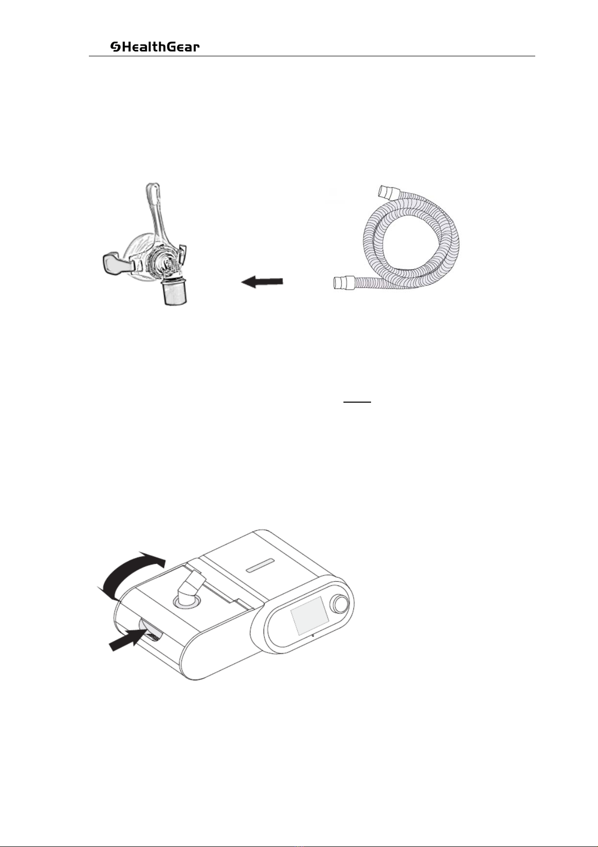
3.2.3 Connect the hose to the mask
Connect either end of the hose tubing supplied with your equipment to your mask.
The mask may have been included as part of a package, or can be purchase separately.
Any brand of mask will fit on this hose.
3.2.4 Fill the water tank
Before use, please ensure the water within the tank is below the max indicator line.
Warning: Do not activate the humidification function when there is no water tank or no
water within the water tank.
Remove the water tank by pressing the lid release button on the upper cover of the humidifier
and gently lift the cover upwards.

UserManual MK/YF38-07–V2.01CS
©2019AllRightsReserved
Pa
g
e 20 of 60
Fully open the humidifier cover lid and slide the water tank out of the main unit.
Carefully add distilled water into the water tank. Do not over-fill and do not operate without water,
unless the humidifier heating is set to OFF.
Slide the water tank back into the humidifier.
This manual suits for next models
1
Table of contents


