Health in motion Sunset Swings 422SB Supplement
Sunset Swings®
By Health In Motion,
LLC
!
!
!
!
!
!
!
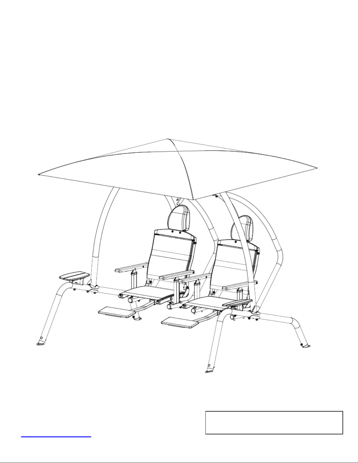
Model 422SB
Dual Recliner Swing
Assembly & Operation Manual
!
!
!
Record Serial Number Here
!
!
!
!
www.sunsetswings.com !
!
September 2018

!
Caution
:
READ! VERY
IMPORTANT
FOR ADULTS
ONLY
Ensure that the 422SB swing is set up on a firm level surface.
!
!
Make sure the swing has completely stopped before entering or exiting the swing. Be
careful as the swing may shift while sitting down or getting up from the swing.
!
!
The foot rest should be tucked under the seat when entering or existing the swing.
!
!
Keep all body parts within the swing seat while in motion.
!
!
Make sure bystanders are at least 5 feet away from the swing while it is in motion. Be
careful placing the swing too close to a structure as severe injury might occur if a
person gets caught between the structure and the swing or damage might occur if the
swing hits the structure.
!
!
Be cautious swinging while children are present as they may stray into the path of the
swing.
!
!
Review the maintenance schedule before each use to ensure the swing is in good
working order.
!
!
This swing is for casual relaxation swinging only.
!
!
In freezing climates, the canopy should be removed, folded and stored in a dry place before the
first freeze or snow and until the last freeze or snow has passed. Failure to follow these
instructions can cause damage to the canopy or canopy rods and will void the warranty.
!
!
The canopy is not designed for high winds. If high winds are expected, please remove the
canopy. Failure to follow this instruction can cause damage to the canopy or the canopy rods
and will void the warranty.
!
!
The swing uses a natural hardwood which might contain slight imperfections.
!
!
!
!
Page 1

!
Thank you for choosing Sunset Swings®. Please read the contents of this manual
thoroughly.
The information inside will help you in many different areas. You will need to send in
your
customer registration card at the back of this manual to validate your warranty. You may
also
complete your customer registration at
www.sunsetswings.com.
!
!
!
!
!
Table of Contents
!
Positioning Your Swing 3
!
!
Tools Required For Assembly 3
!
!
Helpful Installation Hints 3
!
!
Exploded Swing Diagram 4
!
!
Hardware and Tool Diagram 5
!
!
Parts and Hardware List 6
!
!
Assembly Instructions 7-16
!
!
Adjustments 17-18
!
!
Weekly Maintenance Information 19
!
!
Safety Information 20
!
!
Label Reference 21
!
!
Limited Warranty 22
!
!
Warranty Claim Procedure 22
!
!
!
!
!
!
!!Sunset Swings® by Health In Motion LLC reserves the right to alter the specifications of this product at any time.
!
!
!
!!!!!!!!!!!!!!!!!!!!!!!!!!!!!!!!!!!!!!!!!!!!!!!!!!!!!!!!!!!!!!!!!!!!!!!!!!!!!!!!!!!!!!!!!!!!!Page 2

!
Positioning Your Swing
!
!
1. The swing is designed to be installed on a firm level surface.
!
!
2. There should be a minimum clearance of five feet in front and back, and two feet on
each side of your swing. It should be placed in an area where children will not stray
or walk into the path of the swing.
!
!
3. Be careful placing the swing too close to a structure as severe injury might occur if
someone gets caught between the structure and the swing or damage might occur if
the swing hits the structure.
!
!
!
!
Tools required for assembly
!
!
1. 10, 14, 17 and 19 mm box or ratchet wrench
!
!
2. 4, 5 and 6 mm Allen wrenches (supplied with the hardware)
!
!
!
Helpful installation hints
!
!
1. At least 2 people are required to assemble this swing. Some parts are
large and heavy. Use care when handling.
!
!
2. Identify all of the parts for your swing. Empty the boxes and lay out the parts for
identification using the Parts List.
!
!
3. Read all the way through the instructions completely before beginning the assembly.
!
!
4. Do not tighten hardware completely until instructed. It helps to have some adjustment
for bolt alignment while you are connecting parts. Follow the tightening sequence as
mentioned in the steps. After you have completed the assembly, recheck
that all hardware is secure and tight.
!
!
!
!
!
!
Page 3

Page 4
65
55
67
24
31
17
5329
10
72
56
53
34 3419
43
71
69
56
35
30
11L
71
26 22R
19
12L
68
65
57
714
12R
11R
40
41
38
46
64
54
5958 555423
33
13
EXPLODED DIAGRAM
34
31
52
52
9
62
18
9
2
62
62
21
18
262
49
1
68
57
36 22L
52
52
5
39 5225
21
44
61
51
49
3R
1
73
50
873
50
504
51
3L
50
20
63
27
48
67
14
66
16
6
8
25
26
27
28
28
28
28
30
30 30
32
33
33
33
34
35
36
38
38
39
40
41
43
43
44
44
44
44
45
4545
45
45
45
45 45
4545
45 45
45
45
45
45
45
45
45
76
76
47
47
48
61
61
61
61 61
61
61
61
61
63
64
64
64
64
6464
66
66
66
66
70
70
70 70
70
70
70
70 70
70
70
70
70
70
70
70
70
72

!
Page 5
#46 M8 Lock Nut (Qty 4)
#56 M5 x 5
8" Socket Cap Head Bolt (Qty 4)
#50 M12 x 1 3
8" Hex Head Bolt (Qty 8)
#49 M10 x 3 1
2"Button Head Bolt (Qty 4)
0
0 1 2
mm
2"1" 3"
345 86 7
4" 5"
119 10 1412 13
6"
15
#53 M10 x 2 1
4" Carriage Bolt (Qty 8)
#51 M10 x 3 1
4" Carriage Bolt (Qty 2)
#52 M10 x 2 3
4" Carriage Bolt (Qty 16)
#55 M6 x 1 7
8" Hex Head Bolt (Qty 4)
#54 M6 x 1 1
8"T-Nut (Qty 4)
#63 M10 Flat Washer (Qty 2)
#61 M12 Flat Washer (Qty 16)
#70 M10 Arc Washer (Qty 30)
#66 M6 Flat Washer (Qty 16)
#64 M8 Flat Washer (Qty 1 6)
#45 M10 Lock Nut (Qty 32)
#44 M12 Lock Nut (Qty 8)
#72 M5 Lock Washer (Qty 4)
#57 M8 x 4 1
8" Button Head Bolt (Qty 4)
#58 M6 x 1 1
2" Button Head Bolt (Qty 4)
#76 M8 x 1 5
8"HexHead Bolt (Qty 4)
#68 M6 x 3
4" Button Head Bolt (Qty 4)
#69 M6 x 2 3
4" Button Head Bolt (Qty 2)
#41 M6 x 1 1
8" Hex Head Bolt (Qty 4)
#47 M10 x 3 1
8" Carriage Bolt (Qty 2)
#59 M6 Fender Washer (Qty 4)#60 TOOL:4mm Allen Wrench (Qty 1)
#38 M6 Lock Nut (Qty 10)
#42 M8 Fender Washer (Qty 4)
#43 M10 Big Flat Washer (Qty 12)
#74 TOOL:6mm Allen Wrench (Qty 1)
#75 TOOL:5mm Allen Wrench (Qty 1)
#48 M10 ThickLock Nut (Qty 4)
#67 M8 x 5
8"Button Head Bolt (Qty 4)

!
!
!
Page 6!
Part# Description Q'ty (pcs) Part# Description Q'ty (pcs)
1Bent Leg 238 M6 Lock Nut 10
2Curved Flange 239 Bearing 4
3L Right Upright Assembly 140 Dock Washer 4
3R Left Upright Assembly 141 M6*1 1/8" Hex Head Bolt 4
4Top Beam Assembly(with Bearing Housings installed) 142 M8 Fender Washer 4
5Bearing Housing 243 M10 Fender Washer 12
6Adjustable Canopy Support Assembly 144 M12 Lock Nut 8
7Extension Spring 445 M10 Lock Nut 36
8Pivot Shaft 246 M8 Lock Nut 4
9Swing Support Arm 447 M10*3 1/8" Carriage Bolt 2
10 Seat Frame 248 M10 Thick Lock Nut 4
11R Left Seat Bottom Tube 249 M10*3 1/2" Button Head Bolt 4
11L Right Seat Bottom Tube 250 M12*1 3/8" Hex Head Bolt 8
12R Left Seat Back Tube 251 M10*3 1/4" Carriage Bolt 2
12L Right Seat Back Tube 252 M10*2 3/4" Carriage Bolt 16
13 Head Board Bracket 253 M10*2 1/4" Carriage Bolt 8
14 Ratchet mechanism 454 T-Nut 4
15 Headrest Base Frame 255 M6*1 7/8" Hex Head Bolt 4
16 Tilting Headrest Assembly(pre-assembled) 256 M5*5/8"Socket Cap Screw 4
17 Footrest Frame 257 M8*4 1/8" Button Head Bolt 4
18 Wood Support Bracket 258 M6*1 1/2" Button Head Bolt 4
19 Fabric 459 M6 Fender Washer 4
20 Canopy 160 4mm Allen Wrench 1
21 Wood Table 261 M12 Flat Washer 16
22L Left Wood Arm 262 M10*3" Carriage Bolt 4
22R Right Wood Arm 263 M10 Flat Washer 2
23 Head Board 264 M8 Flat Washer 16
24 Footrest Pad 265 M10*2 1/8" Button Head Bolt 4
25 Φ1" Spacer 466 M6 Flat Washer 16
26 Fabric Rod 867 M8*5/8" Button Head Bolt 4
27 Canopy Rod 468 M6*3/4" Button Head Bolt 4
28 Swing Foot 469 M6*2 3/4" Button Head Bolt 2
29 Retainer End Bumper 270 M10 Arc Washer 30
30 30*40*45 Deg End Cap 871 ST3.5*1" Wood Screw 8
31 Foot Rest Left 272 M5 Lock Washer 4
32 Foot Rest Right 273 Set Screw 4
33 30*40 End Cap 874 6mm Allen Wrench 1
34
Φ2" End Cap 475 5mm Allen Wrench 1
35 Film Washer 876
M8*5/8" Hex Head Bolts 4
36 Thick Plastic Washer 4
parts list
hardware list
!
!
!
! !
!
!
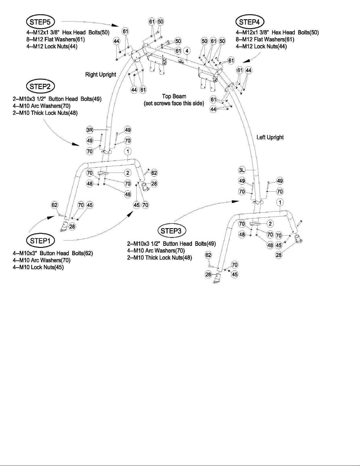
!!!!!!!!!!!!!!!Two people are required for Steps 1 through 5
!
Steps 1. Attach the Swing Feet(#28) to both Bent Legs(#1)
Steps 2 and 3. Attach the Bent Legs(#1) to the Right(#3R) and Left(#3L) Uprights.
Steps 4 and 5. Attach the Top Beam(#4) to the Right(#3R) and Left(#3L) Uprights. Ensure that the Set
Screws that hold the Bearing Shaft to the Top Beam(#4) are facing towards the front of the swing.
!!!
!!!!Wrench tighten all hardware now
!
!
Page 7

!
!
!
!
Step 6. Attach the Canopy Mount(#7) to the Top Beam(#4).
Wrench tighten all hardware now.
Page 8
!
!
!
!
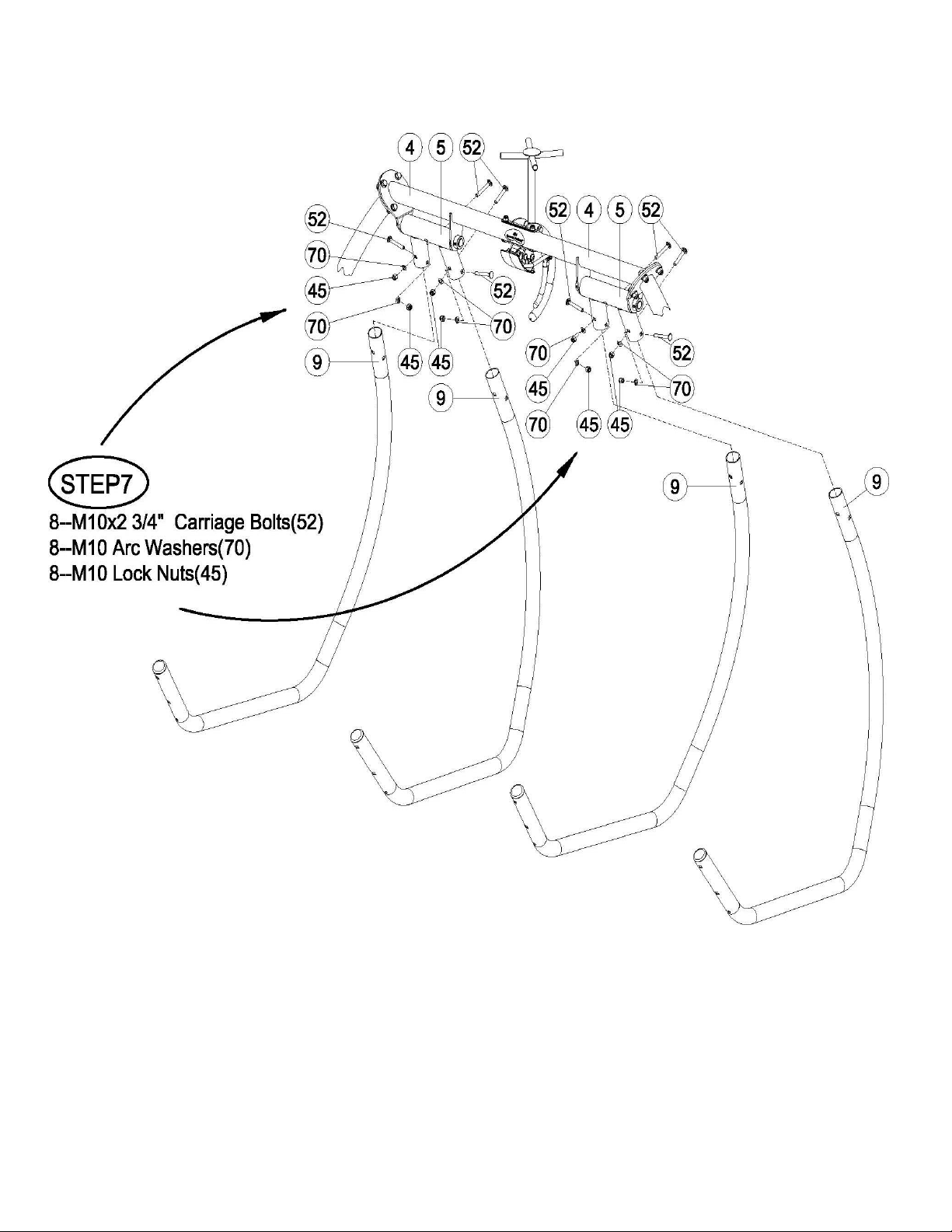
Step 7. Attach the Swing Support Arms(#9) to the Bearing Housing(#5).
Finger tighten the hardware at this time.
Page 9
!
!
!
!
!
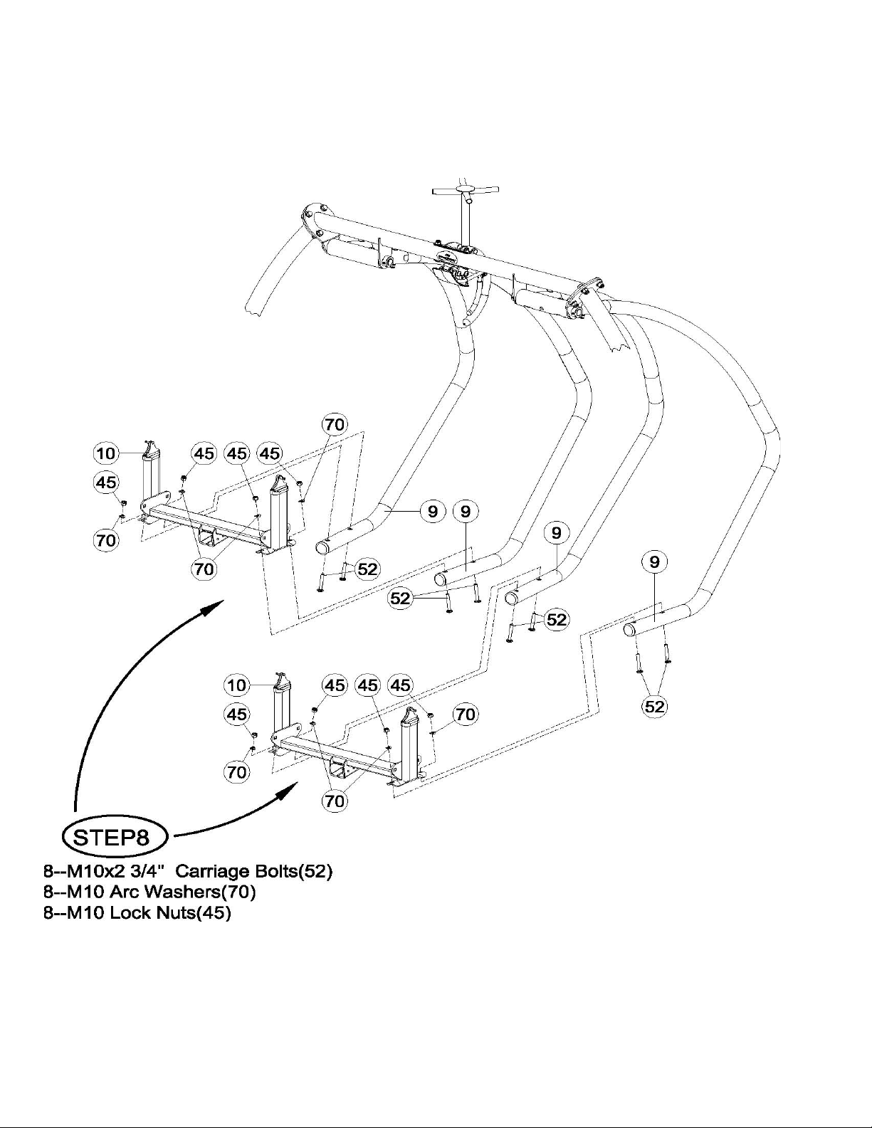
Step 8. Attach the Seat Frame(#10) to the Swing Support Arms(#9).
Tighten all the hardware in Steps 7 and 8 now.
Page 10

!
!
!
!
Make sure the fabric has been fully inserted into the groove of the Seat Bottom Tubes
before tightening the hardware. The fabric can not be adjusted afterwards.
Step 9. Attach the Left(#11L) and Right(#11R) Seat Bottom Tubes to the Seat Frame(#10). Apply the
four nuts to the four 2 1⁄4 bolts with only 3 to 4 turns before continuing to fully tighten each bolt to
stretch the fabric.
This step stretches the fabric. If the hardware on one side of the Seat Bottom Tube is fully tightened
to the Seat Frame before the hardware on the other side of the same chair, the other side can not be
attached without loosening the first side. After applying all 4 nuts by about three turns each,
incrementally tighten all 4 nuts in sequence until the Seat Tubes are fully tightened against the Seat
Frame Flanges.
Repeat Step 9 for the other seat.
Wrench tighten all the hardware after getting all 4 nuts started on the bolts.
Page 11

!
Step 10. With the metal ratchet mechanism, under each wooden armrest, placed so that it is closest to
the Seat Frame Mounting Arm, attach the end of each Left(#22L) and Right(22R) Wood Arm to the
Left(#12L) and Right(#12R) Seat Back Tube.
Step 11. Hook the forward end of the Extension Spring to the top of the Seat Frame Mounting Arm
as shown in the circle in the lower right area of the picture.
Mount the ratchet mechanism under the Wood Arm to the Seat Frame. Repeat Steps 10 and 11 for
the other seat.
Wrench tighten all hardware now but do not over tighten the arms or ratchet which
would prevent smooth motion for the seat back adjustment.
Page 12

!
!
!
Step 12. Attach the metal Head Board Bracket(#13) to the Right(#12R) and Left(#12L) Seat Back Tubes.
This step stretches the fabric at the top of the seat back. Start the hardware with just 3 to 4 threads until
you get both sides started. Continue to tighten the bolts until you can get the hardware in Step 12 started.
Step 13. Finish attaching the metal Head Board Bracket to the Right and Left Seat Back Tubes.
Repeat Steps 12 and 13 for the other seat.
Wrench tighten all the hardware now.
Page 13
!
!
!
!
!
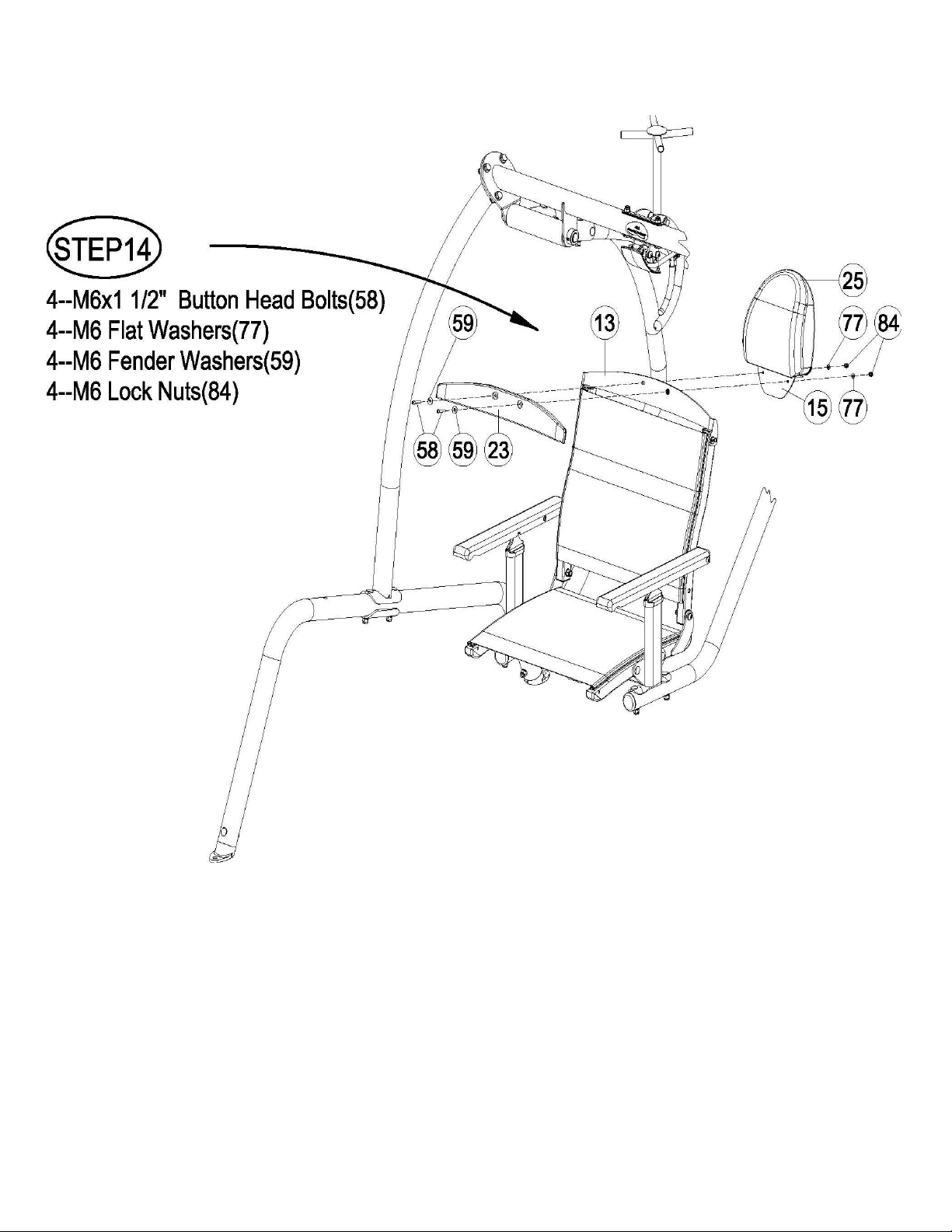
Step 14. Attach the Head Board(#23) and Head Rest(#25) to the Head Board Bracket(#13).
Complete Step 14 for the other chair
Wrench tighten all the hardware now
Page 14

!
Step 15. Attach the Footrest Pad(#24) to the Footrest Frame(#17).!Step 16. Attach the Retainer End
Bumper(#29) to the back of the Footrest Frame(#17).
Complete Steps 15 and 16 for the other chair
Wrench tighten all the hardware now but do not over tighten or damage will occur the
Footrest Pad and the soft rubber Retainer End bumper.
Page 15

!
Step 17 and 18. Attach the table Wood Support Brackets(#18) to the Bent Legs(#1) and attach the Wood
Table(#21) to the Wood Support Brackets(#18). Tighten the hardware now.
Step 19 Place the Canopy Rods(#27) into the rod holder tubes on the Canopy Support Assembly(#6). They will
just sit in the tubes until the Canopy(#20) is put on the swing.
Note: If the canopy is too cold it will not stretch enough to get it over the last canopy rod.
Place the canopy in a warm room of the house until it warms up enough to stretch over the
last canopy rod.
Step 20 The Canopy is a rectangular piece of fabric with pocketed corners. Begin by laying the canopy on
top of the Canopy Rods. Then slide one of the pocketed corners of the Canopy onto one of the Canopy
rods. Continue around the Canopy until the last corner. Getting the last corner onto the Canopy Rod
requires stretching the fabric by pulling the canopy fabric towards the end of the canopy rod and slightly
down. Continue stretching the Canopy towards the end of the Canopy Rod until it slides into the corner
pocket of the Canopy.
Page 16
!
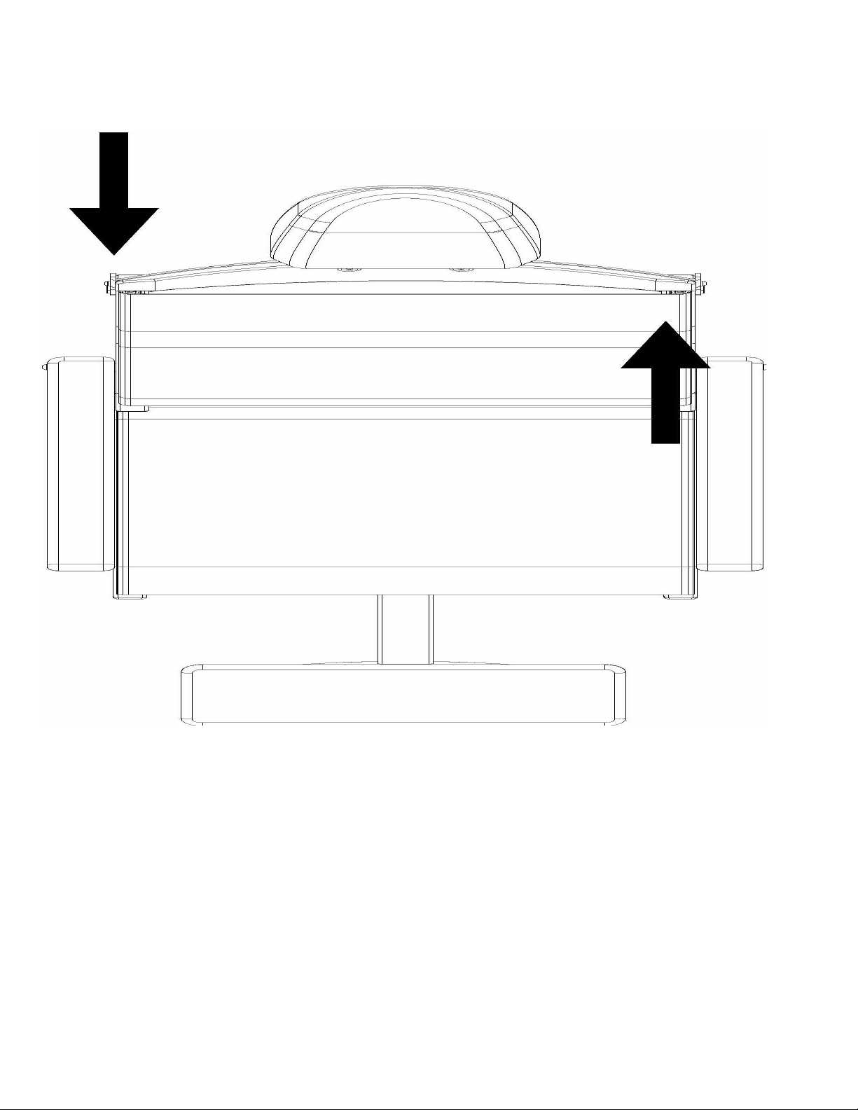
Seatback Adjustment
The seat back may need adjustment to appear even on both sides when looking down
from on top or if both armrests are not catching to hold the seat back firmly in place when
you lean back in the chair. Looking down from the top of the seat back if one side of the
seat back is further back than the other, gently twist the Seat Back Tubes to alter the seat
back’s natural position until it remains even without any force. Pressure should only be
applied in the directions shown above or in their reverse directions. When properly
adjusted, the ratchets on both sides of the seats will engage at each position at the same
time as the seat back is reclined and raised.
Page 17

!
Headrest Adjustment
If the headrest rotates too easily or too hard, adjust the resistance by tightening nut to
increase resistance or loosening the nut to decrease the resistance.
Page 18

!
422SB Swing Weekly Maintenance
!
!
Inspect and familiarize yourself with the safety warnings and other information that
is posted on the decals located on the swing or in the owner’s manual.
!
!
Inspect all fabric areas for tears and fabric seams for loose or damaged threads.
Replace immediately if needed.
!
!
Inspect all the hardware for proper tightness, Retighten if needed.
!
!
Inspect the wood for weather cracking. The wood is a natural product and there might
be slight imperfections that are visible. During normal weathering the wood may crack
slightly due to changes in moisture. This is a natural occurrence and does not affect the
structural integrity of your swing. The wood should be treated every 3 months, or as
needed, with a wood preservative. See your local hardware retailer for suggestions for
wood preservatives. Failure to protect the wood will void its warranty.
!
!
The canopy is not designed for high winds. If high winds are expected remove the
canopy. Failure to follow these instructions can cause damage to the canopy or canopy
rods and will void the warranty.
!
!
In freezing climates the canopy should be removed, folded and stored in a dry place
before the first freeze or snow and until the last freeze or snow has passed. Failure to
follow
these instructions can cause damage to the canopy or canopy rods and will void
the warranty.
Page 19
Table of contents
Other Health in motion Baby Swing manuals

Popular Baby Swing manuals by other brands


CANGAROO
CANGAROO JESSICA instruction manual

Kids II
Kids II Bright Starts Kaleidoscope Safari manual

Fisher-Price
Fisher-Price P6135 Assembly instructions

Swing King
Swing King Noortje quick start guide

Graco
Graco Simple Sway owner's manual

Barton
Barton HELICOPTER SWING 96196 Owner's manual and safety instructions


