Mainstays MSS129900298041 User manual

MSS129900298041/42/43/44
Need Assistance?
Contact our toll free Customer Service Hotline at:
(877) 980-6928
-Monday through Friday 7:30am until 3:30pm PST-
ASSEMBLY AND CARE GUIDE
MAINSTAYS BELDEN PARK
3-PERSON DAYBED SWING

2 YEAR LIMITED WARRANTY
WHAT IS COVERED
We warrant the frame to be free of manufacturing defects to the original purchaser for two years.
WHAT IS NOT COVERED
This warranty does not cover commercial use, hardware, acts of nature, fire, freezing, and abusive use. In
SAVE THESE INSTRUCTIONS
PLANNING ASSEMBLEY
Warranty
WARNING: This swing was made for the explicit purpose of providing outdoor functions and is not
to be used as a toy. This product is intended for normal outdoor use; however, the manufacturer recommends
storing and / or covering this swing when any formidable / severe weather is approaching.
required.
Keep children away during assembly. This item contains small parts that can be swallowed by children.
Children should always be under direct adult supervision while using this product.
○
○
○
○
1
MSS129900298041/42/43/44

LEG CAP
CANOPY/
FRAME CONNECTOR
PLASTIC SCREW
PLASTIC JOINT COVER
SUSPENSION SPRING
BOLT M8*75
WASHER M8
JAM NUT M8
BOLT M6*60
BOLT M6*40
WASHER M6
JAM NUT M6
BOLT M6*25
PLASTIC SLEEVE
RATCHET TOOL
WRENCH
No. Picture
AA
BB
CC
DD
EE
FF
GG
HH
II
JJ
KK
LL
MM
PP
NN
QQ
OO
A. Read instructions thoroughly. Acquaint yourself with the inventory of parts and the
accompanying drawings to ensure safe and proper assembly.
B.Lay out all of the parts on a flat surface and identify them using the table bel
TOP CROSS BEAM
UPRIGHT SUPPORT
REAR CROSS BRACE
LATERAL CROSS BRACE
SWING ARM TUBE
SIDE CANOPY BRACE
FRONT/REAR CANOPY BRACE
LEFT SEAT ARM
RIGHT SEAT ARM
SEAT FRONT SUPPORT
SEAT REAR SUPPORT
SEAT ASSEMBLY
CANOPY
CUSHION
ow.
No. Qty Picture
A
B
D
E
F
G
H
C
I
J
K
L
M
1N
1
4
1
2
4
2
2
1
1
1
1
1
1
Qty
4
2
2
4
2
2
4
2
6
12
18
1
2
4
36
2
4PLASTIC WASHER
2
MSS129900298041/42/43/44

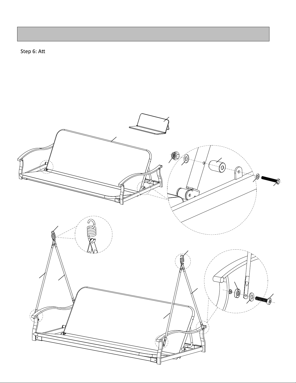
and jam nuts(LL). Tighten all of the nuts and bolts.
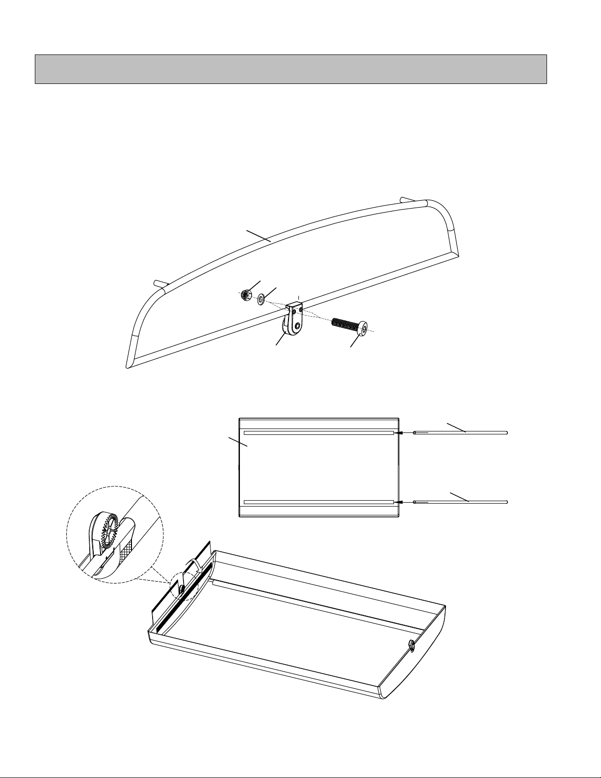
Step 4: Insert the leg caps(AA) into all of the base feet(B).
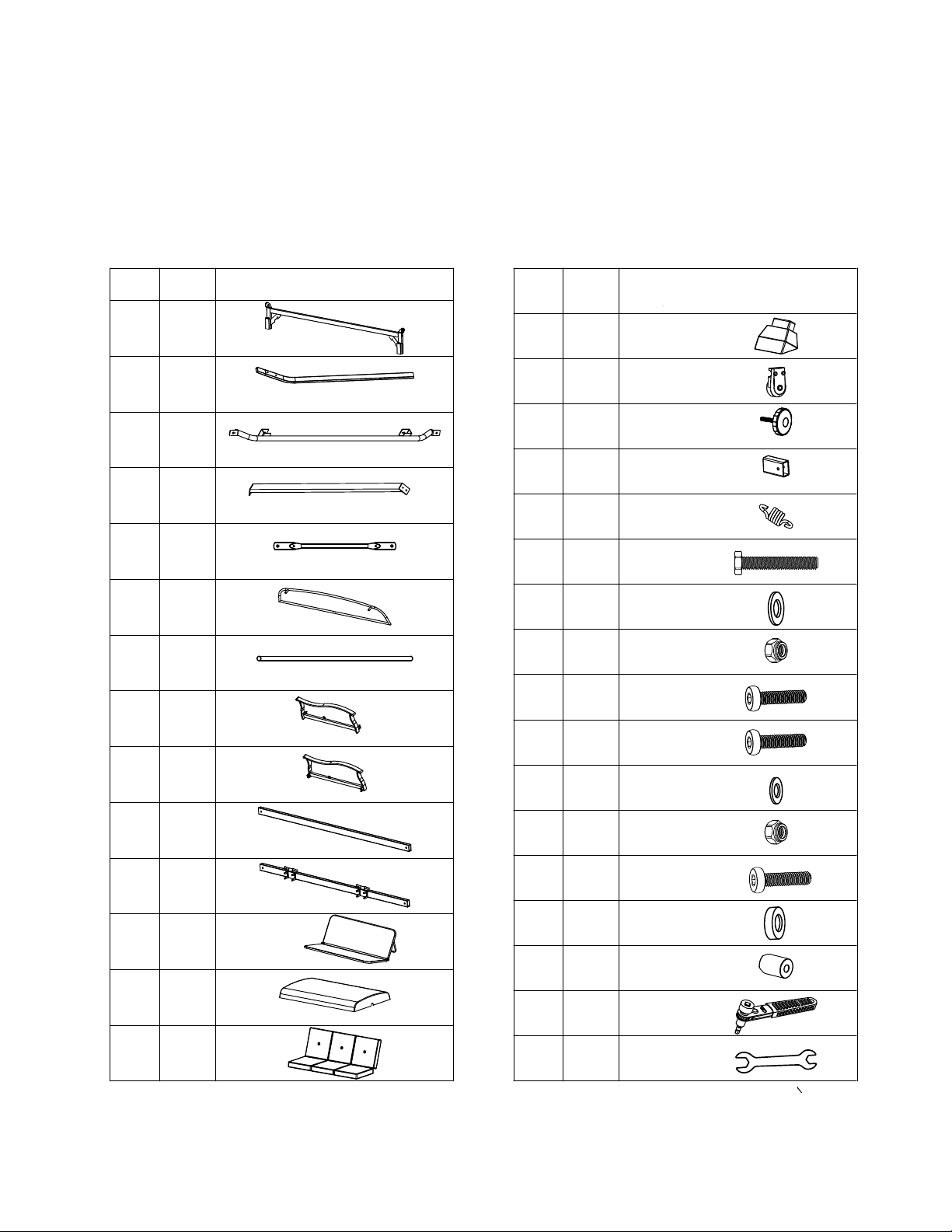
Fig A
Assembly
Note 1: When fastening with nuts and bolts, always use a washer(KK) between the tube and the bolt or the
tube and the nut.
Step 1: Insert the upright supports(B) into the top cross beam(A) separately, then assemble together
by using bolts(II), washers(KK) and jam nuts(LL).
Step 2: Fasten the lateral cross braces(D) to upright supports(B) by using bolts(JJ), washers(KK),
and jam nuts(LL). Repeat the same procedure for both sides.
Step 3: Fasten the rear cross brace(C) to the rear upright supports(B) by using bolts(JJ), washers(KK),
A
B
B
II
KK
LL
Step1 KK
B
B
JJ
D
C
D
Step4
Step2
Step3
AA
KK
KK
LL
JJ
KK
KK
LL
NOTE:
3
Note 2: Do not tighten the bolts after step 1. Fasten all of the bolts after step 4.
MSS129900298041/42/43/44

Fig B
Assembly
Step 5: Link seat arms(H&I) and support tubes(J&K) together through plastic joint cover(DD). Fasten them
by using bolts(JJ), washers(KK), and jam nuts(LL).
H
I
J
K
DD
DD
DD
DD
Step5
JJ
KK
KK
LL
4
MSS129900298041/42/43/44

ach the seat(L) to seat frame by using bolts(FF), washers(GG), jam nuts(HH) and plastic sleeve
(OO). Repeat the same procedure for both sides.
Step 7: Attach the swing arm tubes(E) to seat arm by using bolts(JJ),washer(KK) and plastic washer(NN).
Repeat the same procedure for both sides.
Step 8: Hook the suspension springs(EE) into the top of both holes in the swing arm tubes(E). Repeat the
same procedure for both sides.
Fig C
Assembly
L
L
GG
KK
GG
HH
FF
OO
Step6
Step8 Step7
EE
EE
EE
E
E
NN
JJ
5
MSS129900298041/42/43/44

Step 9: Hang the opposite ends of the suspension springs(EE) into the holes located in the angled
braces on the top cross beam.
Fig D
Assembly
Step9
EE
+
6
MSS129900298041/42/43/44

Step 10: Assemble connector(BB) onto the side canopy brace(F). Fasten them together by using bolts
(MM), washers(KK) and jam nuts(LL). Make sure that the teeth on the canopy/frame connectors
Fig E
Assembly
Step10
M
G
G
Step11
Step12
7
are facing toward the inside of the frame.
Step 11: Insert the front/rear canopy braces(G) into the sleeves of the canopy(M) on both sides.
Step 12: Assemble canopy(M),front/rear canopy tubes(G) and canopy brace(F) together as picture shows.
F
BB MM
LL KK
MSS129900298041/42/43/44

Step 13: Assemble top canopy to bottom frame by plastic screws(CC) at both sides.
Step 14: Put cushions(N) on the frame as picture shows.
Fig F
Assembly
Step13
Step14
N
CC
8
MSS129900298041/42/43/44

Step 15: Make sure that the safety locks on the seat rear support are fully locked whenever the seat
assembly is in a swinging position(left picture). To have the swing in a bed position, open both of
the safety locks(right picture).
Fig G
Assembly
LOCK UNLOCK
Step15
the support brace into the rear cross brace(C). The seat assembly should now be in a secured
Warning:
children.
9
MSS129900298041/42/43/44

Fig G
Assembly
Maintenance
Special Warnings
The user of this swing should always inspect it before each use.
such as fences, garages, houses, overhanging branches, laundry lines, or electrical wires.
Make sure that the suspension springs are properly secured before each use.
damage to its parts.
or its parts.
Oil all of the metal parts that move regularly.
The weight limit is 500 lbs.
.We recommend the use of furniture covers and put cushions aways when not in use.
○
○
○
○
○
○
○
○
○
○
○
Step16
10
safety of your swing.
In order to prolong the life and beauty of your swing , we recommend that it be stored in a dry and
protected area during off season periods.
MSS129900298041/42/43/44
This manual suits for next models
3
Table of contents