Heart Interface HF12-1200 Programming manual

HEART INTERFACE
HFL}-IaOO POWER INVERTER
OWNERS MANUAL
and
INSTALLATION GUIDE
Heart Interface Corporation
811 lst Ave. South
Kent, WA 98032
(206) 8s9-0e+0
8?ztt t{
Copyright, 1990, Heat Interface Corporation
Alt Rights Reserved
I
$ earr.a o.,,'rya.dFp..

1
INTRODUCTION
CONGRATULATIONS! You hay_e_pyrchased the finest mobile AC power sysrem
available. This manual describes the HFl2-1200U and the HFl2-1200U*. fne HFl2-
l?0tUl:quipp_e_d with a Ground Fault Circuit lntenupter (GFCI) outler on the front panel.
The HF12-1200UW has no outlet and is supplied witli a 3 foot ourpur cable from the back
which terminates in a junction box.
TheHFl2-1200 powerinverteris designed tobe installed and forgotren. Ir will give you
many years of uncompromising service, but as with any sophisticatedllectronic eq,iip.ulnt,
you must_respect its.requirements. This manual will explain those demands and gui^de you
through the installation procedures.
IMPORTANT POII\TS
Take care to observe correct polarity when connecting the batteries to the Heart. Reverse
polarity connection, even for a moment, will damage the unit and void the warranty.
Do not feed AC from the utility line or a generator into the oueur of the inverrer. This
is known as backfeeding, will damage the unit and void the *arranty. Always use a gansfer
switch when shore power or generator power is available.
INSTALLAfTON
SELBCTING AN INSTALLATION SITE:
There are several considerations which go into selecting a location to mount your
inverter. First is saf9.ty, but cable length, ventilation and coolin!', operating temperature and
environmental conditions must also be considered.
The F{F12-1200U is not ignition protected, and therefore must nor be mounted in the
pre^sence of ignitable gases, vapors, dust or liquids or in any other "HAzardous Location" as
definedby the National Electric Code. Do not mount in the engine room of a gasoline powered
boat or in an airtigtrtcompartment with the baneries. If in doubr about a pirticular iocation,
consult a qualified electrician before installing the product.
- Although it is.designed to be quite rugged, it is best ro prorecr rhe inverter from the
elements. Do not allow water to splash on the unit and avoid tenlperature extremes. The
inverter will work best in an ambient air temperature between 30 and 104 degrees F. (- 1 and
40 degrees C.).
The inverter may be mounted horizontally or vertically. It is importanr rhat the unit be
secured to a flat surface that will allow air to flow under rhe unit. You should ofro piouiOi
for some air flow around the unit. This will insure adequate cooling when operating high
powered loads.
It is best to locate the unit as close as practical to the batteries so as to keep the cables
short. It is better to ru-nlonger AC wires than longer DC cables. If you must alter the cable
length, use l/0 (00) AWG cable. Do not exceed a-10 foot DC cable iength, due to excessive
voitage loss. See the battery connection and fusing section for more iiformation.

- Ttg ilverter is provided with mounting flanges to allow you to secure the unit. Keyhole
shaped holes in the mounting flanges will facilitate mounting on a wall or bulkhead. When
bolting to either a shelf, a wall or bulkhead use U4 inch stainless steel bolts with lockwashers.
Tighten to 2O-25 ft./lbs. of torque. You will notice that this compresses the rubber feet
somewhat. This is intentional.
INSTALLATION PROCEDURES:
For marine installation, all cable and wires used in these procedures should be stranded
and should meet United States Coast Guard regulations. There are rhree major steps in the
installation procedure. Each step is described and discussed below. Please read the entire
procedure before beginning the installation.
First: Connect the ground
Second: Connect the AC oufput
Third: Connect the battery bank
GROUND CONNECTION:
You must begin the electrical installation by grounding the unit to either an earrh ground
(fornon-mobile land installations), or the vehicle chassis (for RV installations) or the vessel's
grounding system (for marine applications). On the back of the inverrer you will find a
connector labeled CHASSIS GROUND. This is for the purpose of connecting the chassis of
the inverter to ground. You will also find an identical connecror labeled eqUIPUENf
GROUND. Thisisfortheplrpo_seof connecting anyequipmenr rorhe groundingiystem. The
CHASSIS GROUND andEQUIPMENT GROUND are electrically bonded togeitrer. Use a
green insulated 8 AWG stranded copper wire for your ground wire.
PROCEDURE:
1. Measure and cut the required length of ground wire for your parricular appli-
cation.
2. Remove 114 inch of insulation from one end of the ground wire and insert the
bare copper wire into the hole in the ground connector. Use a flat blade screwdriver
to tighten down on the connector. Be sure the connection is very solid.
3. Attach to other end of the green wire to the selected grounding location. This
will vary depending on the installation.
Discussion:
will be either a water pipe or a copperrod pounded into the ground or an existinfground rod.
In a vehicle connect the wire to the vehicle chassis. Make surc the connection is
electrically sound- Also make sure that your selected site is electrically anached to the chassis
itself. Some metal parts on some vehicles are electrically isolated from the frame by rubber
or plastic mountings

In marine applications you will connect to the existing grounding system.
The ground lugs in the output sockets of the inverter are connected to the chassis ground.
In W models the green wire in the junction box is connected ro the chassis ground. Thii means
that when you plug an appliance with a standard 3 wire grounded plug into the inverter, the
ground from the appliance is connected through the inverter to ground.
The neutral wire of the AC output is attached to ground in the unit. This means that when
you connect the chassis to ground, you are also connecting the neutral leg to ground.
\The battery cables from the Heart are not connected internally to the chassis. You may
ground either the positiv€ or the negative battery.
Vt is very important for safe operation that grounding be carefully done. Please do not
operate the Heart without the protection afforded by proper grounding of the chassis.
AC OUTPUT CONNBCTION:
HF12-1200U: This model is equipped with a GFCI outlet on the front panel. The
simplest way to use this model is to plug your appliances into this outlet. You may connect
this unit to your existing electrical system by preparing a 3 conductor wire with a standard
household plug on one end and connecting the other end directly to a circuit breaker panel,
an outlet box or a transfer switch.
V-IF 12- 1200UW: These models do not have an outlet on the front, but are supplied with
a 3 foot cable out the back of the unit which terrninates in an electrical junction box. This is
designed to facilitate hardwiring into your electrical system. Use appropriate connectors in
the junction box and run the output to your circuit breaker panel, outlet box or transfer switch.
Vn order to conform to the National Electrical Code, certain branch circuits must be
equipped with a Ground Fault Circuit Intemrpter (GFCI) such as Pass & Seymour Cat- No.
1591-RW. Any such branch circuit must be protected a circuit breaker consistent with the
GFCI rating. In the case of the HF12-1200U the unit is equipped with the GFCI. In the case
of the HFI2-1200UW a GFCI is supplied separately.
TRANSFBR SWITCHING:
Any time two or more sources of AC electricity are used i n an electrical system a transfer
switch must be used to isolate the sources from one another. The transfer switch is double-
pole double-throw, and may be an automatic relay or a manual rotary selector switch.
IF SHORE POWER OR A GENERATOR CAN BE USED, DO NOTCONNECT THE
INVERTER TO YOUR ELECTRICAL SYSTEM WITHOUT A TRANSFER SWITCH.
THIS CREATES A BACKFEED, DAMAGE WILL R€SULT, AND YOUR WARRANTY
WILL BE VOID.
BATTERY CONNECTION AND FUSING:
Prior to performing this procedur€, you should be familiar with the basics of battery

connection andlzYDc theory. You should understand parallel and series hook-up and how
lo qet $ql*ggtygJ!1gg and current from your battery bank. These conceprs are described
in the BATTERY INTERCONNECTION section.
CAUTION: Do not arange the batteries in a configuration thar will exceed the rated
input voltage of the unit.
CAUTION: Connecting the inverter to the batteries with reverse polarity, even for an
instant, will cause damage and void the warranty. Ensure correct polarily before connecting
the DC lines.
BATTERY CONNECTIONS:
The inverter is supplied with two battery cables, each 36 inches in length. Both cables
ar-e.black, but the positive (+) cable has a red end. If you need to exrend the cables beyond
36 inches, you-must extend the cables supplied with 1/0 (00) AWG srranded cable of up to
!leet.AgTn, do notexceed 10 feet of battery cable, as you will incur excessive voltage lbss.
You must be absolutely certain to maintain correct polarity when changing to a longei cable.
Always install a red cable or a red cable end marker on the positive (l) cable.
Fusing:
The tIF12-1200U and I{F12-1200UW are UL Listed for both marine and RV appli-
cations. The listing is nullified if installation is not accompanied by appropriate baiiery
fusing, ?s per 33 CFR-183.46A for marine applications, and as per NEC-551-'51(e) for RV
applications.
_ _ _ Fo1.*arine applications, the fuse must be within six feet ( I .8 meters) of the battery. For
RVapplications the fuse must be readily accessible and be within 18 inches (.45 meier) of
the battery.
. .The average *!ng ojthgfgsg must not exceed the value appropriate for the gauge and
insulation of the cables. The FIF12-1200U and HF12-1200UW bome with strand-ed iables
with 90 degree C. rated insulation. Therefore you must use a class J fuse rated at 200 amps.
_ Current may flow momentarily when the battery connection is made, as a result of
charging acapacitorinsidetheunit. This isnotcausefoialarrn, however, donoimake thefinal
connection in the presence of flammable gas such as that from charging batteries.
Wiringnotes:
Certain minimum criteria must be met in wiring your inverter. Always use at least 16
AWG suanded wire for your AC output. In marine applications, always select UL listed boat
cable. {or 91her_applications, use moisture and fuef resistant insulated cable. Always use
sfanded cable. Stranded cable joins at connectors far more feliably than solid wire. -
BATTERY INTERCONNECTIONS
. If you will be using-more than one battery to power the Heart it is important that the
battery interconnections be made correctly.

-Whq using 6 volt batteries you must hook up pairs in series ro ger l2 volts. In a series
configuration y9g connec-t the p^ositive post of oni banery to rhe neg[tive post of the orher.
Twelve volts will be available from the remaining two pbsts.
When using 1.2. volt batteries-yoo hgo$ them up in parallel. In this configuration you
connect all the positive' poststogether and all the negative posts together. You inay connecr
the Heart to any pair of positive and negative posts.
If more than one pairof 6 volt batteriei is used you must connect them in a combination
of series and parallel.
When batteries are connected in series the voltage of the banery bank is equal to the sum
of the voltage of each battery. If you connect two 6 volt batteries in series you get 12 volts.
The app-lour capacity,of the battery bank is equal to the amp-hour capaiity o? one of the
batteries.Forexample,ifyou connectapairof 6volt250amp-hourgolf cart baiteries in series
you get aLZvalt 250 amp-hour battery bank.
When batteries are connected in parallel the voltage of the bartery bank is the same as
that of each battery. The- amp-hour capacity is equal to the sum of the amp-hour capacity of
each battery. Forexample, if you connect two 105 amp-hour 12 volt batteiies in paiatlel you
get a L2 volt 210 amp-hour battery bank.
For a final example, if you connectfour 6 volt 250 amp-hour golf cart batteries in a series/
parallel configuration you get a 12 volt 500 amp-hour battery bank.
Use at least 0 (l/.0) gauge_copp€r cable fitted with the proper terminals for your battery
interconnections. Make sure that all connections are clean-and tight.
OPERATION
It is recommended that all loads be turned off or disconnected before turning on the
F"ry. This is especially important for any high powered loads, and is less imporrant f6r small
loads.
To operate simply move the power switch to the on position.
Both LED indicator lights will flash momenrarily. The low battery LED will flash red
and go out first. The overload LED will flash green anci go our after the low battery LED. The
unit is now running and ready to supply AC power to your loads. WHAT TO EXpECT:
There are virtually no limitations to what will operate on your Heart, within the rating
of the unit. You may operate fluorescent and incandeicent lighls, refrigerators and freezers]
computers, televisions, etc- The tist is virtually endless.
Flectrical appliances fall into 2 broad groups, resistive and inductive. Resistive loads are
simple ones in which the electricity createi heat and no morion. Typical resistive loads that
you may operate include incandescent lights or electric heaters.-It is easy to figure what
resistive loads will work on rhe Heart, any resistive road within the rating will opirate fine.
Inductive loads are generally those in which the electricity goes through a coil of wire.
These loads usually contain motors, such as fans and refrigeratoisl or transfo-rmers, which are
found in most electronics such as TVs, computers and huorescent lights. Inductive loads
require a larger amount of power to get them started than to run them, soiretimes up ro 6 times

as much power.-This inductive surgemust be taken in to account when figuring what will
operate on the Hearr.{ good rule of thumb is to figure that your HFl2-i260 wiil operare a
1/3 horsepowerinductive motor. Capacitor-start motors require the minimum surge ro ger
started and are therefore recommended when possible.
THE LOAD DETBCTION CIRCUIT:
Your Heart features a unique load detection circuit that allows it to be left on and to draw
very little power if it is not actually operating any loads.
This circuit is automatic and virtually instantaneous. While in idle or no-load the unir
draws about 65 milliamps (.065 amp) from the battery bank and is putting out about 50 volts
RMS. This will typically be measured as 20-30 volts on an averaging uott merer.
The load detection circuit is set to detect a 7.5 wan load. If you arrempt to operare an
appliance which draws less than 7.5 watts you will have to run an additional load simulta-
neously to insure that the Heart will come out of idle.
Oc-casionally a small inductive load that draws around ?.5 watts will f ail to bring the unit
out of idle. An example might be an electric shaver. If this happens you musr simplf operate
a resistive load in conjunction with the shaver. A l5 watt tighi Uutli will be enougli to force
the unit out of idle if you are running a very small inductivE load.
THE PROTECTION CIRCUITS:
The Heart has 4levels of protection against overloads and ground faults, and a circuit
which protects against excessively high or low banery voltage.
OVERLOAD PROTECTION:
There is a very fast orrerload protection circuit in the Heart to protect against short
circuits. This is activated if there is a short circuit in your wiring ot if you aitempt ro srart a
large-induction motor in excess of the surge rating bf the Heait. The overload protection
circuit is indicated by the overload LED on the front of the unit. This LED will light green
if an overload condition occurs.
The overload circuit will quickly shut down the output of the Heart when activated. If
the short circuit or inductive overload is removed within l0 seconds, the unit will automati-
cally reset and continue normal operation.
If the overload condition pqrsiqtg lor more than 10 seconds the unit will completely turn
itselfoff, leaving the greel ovirload LED_shining. If this situation occurs you ,nurt discover
and eliminate the cause of the overload. Once the overload is removed, yL, *uy restart the
Heart by turning the power switch off, pausing a momenr, and ttren swi"tctringlt Uack on.
CIRCUIT BREAKER PROTECTION:
..- T!" 10 ampcircuit breaker on the front of the Heart is a relatively slow breaker which
will allow the unit to provide ample power to starr inductive loads.
6

If vo.u attempt to -o-perate an 11 amp AC appliance it will run fine for several minures.
The circuit breaker will eventually trip, proteciiirg ttre llearl rrom ;;;il; "perarion over
its rated ourpur. At higher powers theliicuit brealer wili tnp sooner.
When the breaker trips it will pop o!l: extending about 114 inch. To reset simply push
the breaker back in firmly and the unit will restart.
GROUND FAULT CIRCUIT INTERRUPTION:
HF12-1200U: The outlets on the front panel-are equipped with an integral ground fault
circuit intenupter (GFCI). In the case of a giould fautt, ttiii device will ind,'up't the outfut
of the Heart, and the reser burton will pop-out. To resei, push the uurio" uu"-t in.
On the GFCI there are two buttons, the reset and the test button. Monthly you musr test
ll9 G.FCI by turning the unit on and pushing.the test butron. The re.set u"ii""lnlutd pop out.
If it does not pop out, you must taki the uiir in for service.
- Important note: The GFCI test will not work properly if the unit is in idle. you must put
a load on the unit to perform the monthly test.
IIF12-1200UW: In order to conform to the National Electrical Code, certain branch
circuits -t!at may be operated with the HF600-12M musr be equipped with a Grct, such as
fasl a1d Seymour Cat. No. 1 591Rw. Consult the code for details. A CFCI outiit is included
in the box with the inverter.
PROTECTION FROM OVBRHEATING:
BecausetheHeartislo!guite lffiVoefficient, there will be heat built up in the unitduring
the operation of loads which-are close to the.rated ourpur. If a 1200 wait toaO is run lonfi
enough the therrnal protection in the Heart will come into play.
Wound into the center of the transformer is a thermal sensor that will shut down the Heart
if internal tlmperatures approach the maximum rating of ttre components. If this happens the
overload LED will come on, glowing red.
When this occurs you must give the unit time to cool down before re-starting. When the
fTlgets cool enough to start back ,rp, the overload LED will turn gt6n nirr,r,r overload
LED. turns green you may re-staft the unit by turning the power sivirch ro the off position,
pausing for a moment, then turning it on again
HIGH AND LOW BATTERY VOLTAGE PROTECTION:
The Heart will accept battery voltage ranging from 10.5 to 14.5 volts. If rhe voltage of
the battery bank falls ouiside of t-his ranle ttreio# uattery ieD will .o*" on, glowing red.
I.hg lo*. battery light will glow for a fewmoments while ;ho;;r ;;;;;;; iofierate. rr tr,e
high or low batrery voltage_persists the unit will shut itself d;;;;;h; i;; b^,;;y LED will
extinguish and the overload lighr wiu be left on, glowing $een.
The low battery cut out is designed to prevent the banery bank from discharging totally
and thereby incuning permanent dimage. There is a time delay built into this circuit which
l:'.
t:
1,.
Bi

allows the battery volta.ge to momentarilV drof below 10.5 volts. This will allow the voltage
to dip substantially while starting an induction moror.
The high b3tlery cut out is designed to protect the Heart from excessive input voltage.
When this circuit is activated the low battery LED comes on red, just as in the case of the t6w
battery cutout. once the unit shuts down, the green overload tight is left on.
If the low battery L.ED comes on you should measure the battery voltage to determine
if it is high or low. If it is high you are probably overcharging the baitery an? should check
both the charging system and the water level in the battery. If the battery voltage is low then
it is time to recharge
When clgcking for_lo,y battery voltage bear in mind that this low voltage will rebound
when the load is removed. If the low battery protection circuitry shuts the unit down it is quite
likely that the battery voltage will measure higher than the 10.5 volt cutotT point. Put a ioad
on the battery bank and recheck the voltage.
MAINTENAI\CB
The Heart is a solid-state electronic device that requires no maintenance. It is recom-
mended that you clean the unit periodically with a damp cloth.
. . KeegtheHeartdryatalltimes.Ifwatergetsinsidetheunitimmediatelydisconnectfrom
the batteries and dry it out. Make sure it is completely dry before attempting ro use the unit.
WhiletheHeartdoes notrequrlg ally maintenance, it isvery important to performregular
maintenance on the battery bank. This includes checking the electrolyte level'and filling-with
distilled water as necessary, and cleaning all battery cbnnections. keeping the rops 6f tne
batteries clean will help reduce their tendency ro self discharge.
BATTERIES
_ The performance of your Heart Interface will be highly dependent on the battery bank
thatyou use. The following information will help you to understand how to size and miintain
your battery bank.
BATTERY SIZING:
. Th" size of your battery bank will depend entirely on the loads that you operare and the
time between recharges.
We recommend that you use true deep-cycle batteries with your Heart Interface. Golf
cart batterigs are a good choice. RV ormarine deep-cycle batteriei ate acceptable, but do not
have the-life expectancy of the golf cart b.1tt9{y. Do not use auromotive starting barteries as
they will die after o$V u very few a99n-Aipfrarge cycles. Even the 8D rype dlesel starting
batteries will nothold up underdeep disch#ging. ttrere is no substitute foi a true heavy-dut!
deep-cycle battery.
. Gaining increasing popularity is the sealed gel-cell type battery. Several fearures make
these gel-cells attractive, including no maintenance, no chance of spiils, and some types are
capable of accepting a very high charge current for rapid recharging. In addition theinternal

resistance of these batteries is lower than that of conventional lead-acid batteries. This means
!!at the battery voltage stays higher under load, which adds a measure of performance ro the
Heart.
leep-cycle battery c-apfity is expressed in amp-hours, usually this number will refer
ta a20 hour discharge cycle..For example, a 100 amp-6our battery *ill deliuer 5 amps foi ZO
hours. If the discharge rate is greater than 5 amps the overall amp-hours available will be
reduced. Drawing 2! ayns, a 100amp-hour-batlery will deliver only about 80 amp-hours.
Drawing 100 amps the battery will deliver about 45 amp-hours.
. !":!-"ycle batteries can be discharged, sOVo without perrnanent damage. This means
that a 10O amp-hour battery hag S! amps of useful capacity. The number of discharge cycles
in the life of a battery is directly dependent on how deepiy they are discharged. rf lou oniy
draw SAVo of the batJev.cagpity each time before you iecharg-e, your batteiy bank will lait
much longer than a bank of batteries which is discharged, g0% eich time.
To-size your battery bank you need-to determine approximately how many amp-hours
you will consume between charging cycles.-Start by looliing on eacir of your afpfiances ioi
the number of watts that it consumes. Then figure out how miny hours thi apptiairce will run
between- charging cycles. For example, a small refrigerator consume s 240 watts. It will
operate forabout l0hoursperday. This meansitwill consume about 2400 watt-hours perday.
A corollary of Ohm's law tells us that watts equals volts times amps. Therefore, if we divide
$e yatl;.h9urs by our 12 volt battery voltage wE get 200 amp-hours. Figure in about lAVo extra
for inefficigncy, so that this refrigerator will draw about 220 amp-tr6urr p", day from youi
battery bank.
A minimu* oq a 280 amp-hour battery bank will be necessary ro power the above
refrigerator for oneday, assuming that we diicharge the battery bank io gdEo. elarger bank
will allow for less deep dischargrng and longer battery life.
WATTS=VOLTSxAMPS
WATT HoURs = WATTS CONSUMED By APPLIANCE x HOURS oF USE AMp.
HOURS = WATT HOURS / VOLTS
USING BATTERIES:
YourHeart Interface-operates 9n a 12 volt battery bank. The actual voltage of this bank
may_get as low as 10.5 volts or as lriqh as 14.5 volts. Within this range the ouiput voltage of
the Heart will remain constanr at ll9-I2l volts RMS.
. lattery_bank oulput voltage will drop under load. The larger the battery bank the smaller
the voltage drop will be. For ttiis reason it is advantageous toiuur ur rirgdof u i;;i;;fi;;;
as practical, especially if you will be startingiaductiie loads such as reffrgeration motors or
well pumps. In most cases, inductive loads will start easier if the banery "6itug" ir retativeiy
high.
AsyouuseyourHeartyou will find-ituseful tomonitorthe stareof chargeo{yourbattery
bank. This will let you know when it is time to recharge without letting ttre t6* uanery cutour
circuit shut the unit down unexpectedly.
The state of charge of a battery can be measured by two instruments, a hydrometer or
9

a volt meter. Hydrometers measure the specific gravity of the electrolyte in the battery. This
gives you a very accurate measurement of the state of charge but has two significant
disadvantages. Forone, the temperature of the electrolyte will affect the reading that you get.
Unless you measue the electrolyte temperature and make appropriate adjustments you will
not get accurate state of charge readings from your hydrometer. The other disadvantage to
taking hydrometerreadings is that the process tends to be messy. Nor only do you risk getting
banery acid on your clothes but you also risk contaminating the battery electrolyte with dirt.
Contamination in the battery can seriously impair the performance and longevity.
We recommend that you measure the state of charge of your battery bank with a digital
volt meter capable of reading to at least tenths and preferably hundredths of a volt.
The voltage measurement must be taken with the batteries at rest, having been neither
charged nor discharged for several hours. A fully charged battery will read about 12.6-12.8
volts at 80 degrees F. (30 degrees C.) The voltage of a deep-cycle battery that is discharged
to the 507o level will be about 12.2 volts. A battery that is 807o discharged will read about 10.5
volts. These voltage measurements are only slightly affected by temperature.
The ambient air temperature will have an affect on battery performance. Expect
reduced performance from very cold batteries. The rated specifications of a battery are true
at about 77 degrees F. At 30 degrees F. the capacity ofa battery is reduced by about 3OVo. At
0 degrees F. the battery capacity is reduced to about SAVo af its potential.
BATTERY CHARGING:
You may charge your battery bank from several different charging sources including
engine alternators, photovoltaic solar panels, hydro or wind systems, and standard AC op-
erated battery chargers. It is not uncommon for more than one of these sources to charge
the batteries at the same time. You may operate the Heart at all times, whether charging
simultaneously or not.
You must use a battery bank with the Heart. It will not operate on the charging system
alone.
PRODUCT DESCRIPTION
The Heart Interface is made up of a pulse width modulation control circuitry that drives
two banks of Field Effect Transistors (FETs) and a large transformer.
DCaorver enters the Heart through the battery cables and is connected directly to each
bank of FETs. DC is also fed to the Main Circuit Board. The FET banks act as high cument
switches, one bank switches on to create the positive half of the ourput and the olher bank
switches the negative half. Heart Interface uses the latest in ruggedized FETs, which have a
very.low resistance when they are turned on. This allows foi trlgfr surge capability and
efficiency.
The transformer in the Heart is wound, dipped in lacquer and baked in our factory. This
transformer is exceptionally low in resistance and very efficient.
The layout inside the unit places the transformer in the cenrer of the chassis. The FETs
10

I
are mounted on circuit boards which are in turn mounted to the sides of the chassis. In this
way the entire heavy-gauge chassis is used as a heat sink.
The control circuit board is mounted to the front panel. The switch and LED indicaror
lights are mounted onto the main control board. The control board sends o rignuf to the powir
modules turning tle FETs off and on. Circuitry on the control board insures tf;ut tf,e f.eqirency
is_keptstable lt 60 Hz and,.by constantly monitoring rhe output, the voltage is regulited at
120 volts RMS. Also contained on the main circuit 6oard are ttre prorectiJn circuits.
REMOTE CONTROL OPERAilNG PANEL
A flush mount remote- conffol panel with a 20 foot wiring harness is available for the
HF12-_1200U, please specify the RP-9. This plugs into the 9 pin"connecror on the front panel
of the Heart.
. - Jo operate the unit with the remote control you must leave the power switch on the Heart
itself in the OFF position.
TROUBLESHOOTING
. ^Mostproblems will fall into one of three categories. If a problem occurs please refer to
the following guidelines.
LOADS BEHAYING ABNORMALLY:
Most loads will run on the-Heart just like they do on utility power. Occasionally certain
inductive loads will emit a slightly louder hum than normal. Thls is due to ttre Heart ourpur
YaYe shape. If the problem is unacceptable there are sine wave filters available. Contact you.
dealer for more information.
If a small load will not start and run it may be related to the load demand circuit. Turn
on an incandescent light bulb of at least 15 waits and rry the load again.
Digital clocks will ordinarily keep good time on the Heart but occasionally we encounter
one that runs 2 or 3 times faster than normal. This probiem is due ro rhe modifieJ ;i";;;;;
output.
Itis.possible thatthe start-upof alargeinducrive load such as a U3 horsepowerinduction
motor will interfere withthe operation of sensitive electronics such as .o*piiir. What may
happen is that whiie the Heart is surging_to start the big motor, the compur"i *iii"rorh. If you
will be stafln$ a motor which requires the full currenithat the Heart is capable of delivering,
such as a 1/3 horsepower induction motor, do not operute sensitive etectronics at the same
tlme.
Microwave ovens depend on high peak.AC voltage to cook at full speed. The peak AC
voltage oulput of the Hgart is dependenionrhe input b-attery voltage. frre t iglt"r thb banery
yglage the faster the microwave will cook. Do noibe surpriied if y6ur microriuu, oven takes
!57o 1o.25voIo.nget to cook when operated with the Hearr. Cooking rpi"O *ifr n" increased
by raising the battery voltage.
11

MOTORS NOT STARTING:
Because of thelargesurgerequiredtogetthem started, itis sometimes difficulttopredict
exactly which induction motors are within the capacity of the Heart. We have foundthat i/
3 horsepower capacitor-start motors will reliably work on the Heart, even in well pump
applications.
If a problem is encountered getting a motor started the first thing to do is confirm that
your battery voltage is adequate . This must be done while the motor is attenrpting ro srarr. Use
a volt meter and watch the momentary voltage drop while you start the motor. If the voltage
is dropping below 1 1.0 volts this may be why the motor will not start. Check all the battery
connections and the state of charge of the battery bank.
If the connections appear solid and the battery bank is fully charged, bur the voltage
drops below 11 volts, you may want to consider a larger battery bank.
If the voltage does not drop below 11 volts, but the motor will not start, the addition of
a capacitor across the motor may help. Use a motor-run capacitor of about 3 uf.
MEASURING THE OUTPUT VOLTAGE WITH A METER:
You may measure the output voltage of the Heart with your volt meter, however, it is
possible that you will not measure the 119-121 AC volts RMS that the unit provides. This is
due to the output wave shape of the Heart, which can only be accurately measured with a true
RMS volt meter, a rather specialized instrument. Do not be concqJned about measuring
output voltage that varies with load and battery voltage, this is normal and should be expected
unless you have a true RMS volt meter. When measured with a standard volt meter you can
expect readings somewhere between 90 and 140 volts, and since different meters contain
different measuring circuits it is impossible to predict the exact reading you nray get.
_ If you measure the output voltage with nothing plugged into the front of the Heart you
will get a very low reading, usually between 20 and 30 volts AC. This is the no-load or idle
state of the unit and is perfectly normal. True RMS voltage in idle is about 55 volts AC.
. A Slod ryay to confirm that your voltage regulation circuit in rhe Hearr is working is to
observe the brightness of an incandescent light bulb. If the brightness appears about thelame
as the light plugged into utility power or a generator, then you know the voltage regulation
is correct. A relatively small change in voltage will produce a noriceable changeln light
output.
NO OUTPUT FROM THE HEART:
If you are unable to get any output voltage from the Heart the first thing you need to check
is the battery voltage. Confirm that neither dead batteries nor bad conneciions are the source
of the problem.
If the Heart does not hum at all, puts out no power, and displays the green overload LED
continuously, you should contact your dealer or Heart Interface.
t2

WARRANTY INFORMAI'ION
Your Heart Interface is under limited warranty for a period of one year from the date of
purchase' Terms of the wiuranty arespelled out on trt* *ui,runty registration card. please fill
this card out completely and reiutn ifto Hean rni"Juri in order to validate you, warranry.
Heart Interface will qay shipping one. way if your unit requires service within the
warranty period. After this time the Customer isresponriut" io. ail sriipping ;;;;. please keep
the original box and-hard foam packing lutrl4 ir 9-*; t;" need to.ship the Heart for any
reason. Please ship the unI_q"_lglrggpaio and it wilr bi ir1g1q-qeight prepaid to you. IF
YOU SHIP TO UNIT FREIGHT iOiIECr IT WIii dN NEP'USEU.
. - If you think that your Heart requires servicing please contact the factory for a Return
Authorization Number. Heart Interfice,canngr acc-epr unirrli'i'Ii;",.ii; ,ililout this R.A.
Number' You mav use the toll-free number below id;;t;;"tacr you musr make with Hearr
Interface.
800-446-6180
To obtain a Rerurn Authorization Number you must first provide the serial number of
yourHeart- Please have the serial number and moiet nu*Gi.eaov uerore vlu piir" your call.
Depending on you. location, you will get the unit io ;il;t authorized service cenrer or ro
the factory itself.
Please be prepared to show proof of purchase date on any warranry craim.
r3

HFl2-1200 heaft hteffncs
r
1200 Wqtts
Silent AC Power
Reguloted
Voltoge ond Freluency
High Efficiency Throughout
Power Ronge
Automotic Loqd Detection
High Motor Slorling Torque
Anti -Corrosion Conslruclion
Oplionol Remote Ponel
Operates sensitive electronic equipment such as computers, TVs
and VCRs. Output power remains constant, regardless of fluc-
tuations in battery voltage.
High efftcieney meErns extended run time on batteries. Extremely
efficient from 5olo of rated power to full output.
Reduces consumption to only .O7 amp when turned on but not
in use. Unit automatically shuts down at low battery voltage.
Unique circuit allows running appliances and tools whose mo-
mentary starting requirements are marry times their specified
ratings.
Hearry duty marine grade case uses stainless steel and anod?ed
aluminum. Designed to withstand extreme environmental
conditions.
Remote on/off/reset and LED indieators for power status, low
battery, and overload. 20 ft. wiring harness included.
POWER TECHNOLOC
\- . "-neaft fi*#?E
?
HeortlnterfoceCorporotion / 8lI-lstAvenueSouth / Kent,WA98032 / Office: (206)gb9-0640 Foxr (206)959-9079 Tetex: 160563
{} rtinr"a on reryclad paper

Model HF12-1200 $eries heaft htefface
s
8096
4096
20*
3500w
3000w
26O0w
2000w
lsOOw
lo(Xrw
EFFICIENCY VS OUIPUT POWEF
FOR HFI?-.IzOOU INV€RTERS
LOAD SIZE VSnilE UtfflLSfiUTDOWN
FOR HF 12 12OOU INVERTEFS
096 I
'
(t ;!=l]a
oooooo
ooooo6
N{@6gS
900 VA continuous
(a13VDC.TA=2sC
€sEsssE
EEEEEEE
oooDo60 6tNO
Distributed By: * &eort voltage and frequency models,
r.zf [-h== ]r zs"
CONNECTOR
lOAA"
r_----.".:-l
llj ,flBF I
t_ . "t
,t--
t'!
:/7'.
Tl'."-",-;1 tJ-r
'"LLJ;;.#."1't1__J
4,6' pE1y1916 1.7'
s
Heort lnterfoce Corporofion I 8l I - I st Avenue South / Kent, WA 94032 / Office: (206) 859-0640 Fsx: (m6) 859-3579 Tetex: 160063
The statemmts' sPeclllcatlons md data tn thts_Publlstton are belleved to_be camt. Specftcauotr ud data may vary accord[xg to condltions of actual us€, Heart Interface
:^.Y.T_9:l*1_P,-r.t$9-.*gcjl""u.nsandthecontentsofthlsmaterral*11rI!lF": Nowarantylsmaoe,exp"rees;dorrmptr&.uv-uriseusor-*"6"ii.r"r-il8 *"p*t
to my results or lack therof fm tlte use of lnfomatlon tn thls docment. No ltribity ts assrrmed as a rsult of ti's use or applieuon itrr *y Jrecl oi co*.quett"rii o**!us,
-1
*ii
bottery voltoge 12 volts
boftery voltcge ronge .l0.2-]5 volts
low bottery cut-out lO.2 volts
voltoge regulotlon 5% true RMS
output power (mtn.30 mtns) 1200 wcrtts
output voltoge 120 volts AC tarovac. lmvAc)..
frequency regulotion EOt
wove shope modifled sine wove
surge power willstort 1/4 HP inducfive motor
power foctor I io 0.1 logging
efflciency 91,3'6 @ ]200 wotts I 96.6% @ 600 wotts
no lood dloih (w/o remote) 0.07 omp
outomotic lood demond stqndord, no iime deloy
dimensions <oxwxHl 10.4" x 15' x7.2'
weight 42lbs,
remote RP-9 for HF]2-1200U
240 Volt.50 Hz HFr2-r200E
Protection circuit breoker, electronic overlood,
thermol overlood, high/low bottery
consumer worrontv 30 months

Model HFl2-1200 Series heaft inteffaru
r
ro0*
8{}*
60'6
4096
20s
EFFIC|EilCY V$ OUTPUT POWER
FOR HFI2.1 2OOU INVERTERS
LOAD StrE VS TIUE UNT]L SHUIDOWN
FOR HF 12 12OOU INVERTERS
900 VA continuous
@13VDC.TA=2sC
o%l
t
ol!}'''
oooooo
oooooo
qr@ogs
3500w
300qw
2500w
20O0w
1500tv
100OwE€gEg's.E
EEEEE€E
ortgrD665 qNo
Distributed By: * E4Ert voltage md &equency models.
4
r.z'[- [----p-- ]r.zs"
ltt
-+,._+ CoNNECTOR
10.44'
""-3-"%"
..".ffi
.hesrt:€e
4.6', ---J
neuorE l'7'
,o s
Heort lnterfoce Corporotion I 81 I - 1st Avenue South / Kent. WA 98032 / Office: (206) S59{640 Fox: (206) 859-3579 Tetex: 160560
The statments-, specfBtlom md data ln thb-PubUcauon m,bcllwed to_be srrtL SpectRcatlons md data my r amrdtng to mndttions of actual u*. Heart Int€rfacr
ffi6 the dght to. modlry sp€ctflcauons and the contents of thls mtertal 3! 11rI !t-F". No wamty ts mde, oq-nsae'd or imglt&, by the segu or mmufactu* *1th rcspect
$ii
botfery voltoge 12 volts
botfery voltoge ronge 10.2-]5 volts
low bottery cut-out 10,2 volts
voltoge regulotion 5% true RMS
output power (mh. so mins) 1200 wotts
output voltoge 120 volts AC eaovac. rmvAc)..
frequency regulotion .5%
wove shope modiffed sine wove
surge power willstori 114 HP inductive motor
power fqctor I to 0.1 logging
efficiency 91.3% @ 1200 wotts I 96.6% @ 6@ wotts
no lood drQin (w/o remote) 0.07 omp
qutomatic lood demond stondord, no time delcy
dimensions <oxwxnl 10.4"x15"x7.2"
weight 42lbs.
remote RP-9 for HF]2-1200U
240 Volt.50 Hz HFt2-1200E
Protection circuit breoker, electronic overlood,
thermol overlood, highllow boftery
consumer worronty 30 months

lnbmational
@ffi PD.9.510C
tRFZ44
nexfEfo Power MOSFET
. Dynaffic dvidt Rating
| 175"C Operating Temperitr.rre
. Fast Switching
o Easa ol Paralleling
o Simple Drive Requirementrs
Ileacription
Third Generation HEXFETS from lnternatonal Rectitid provide lhe dedgner
with the best combinatlon ol fast oadtching, ruggedized device design, low
on-rE6i€tance and cosl-off€clivon€ss.
Ths TG220 packags ls univercally prefened lor all commercial-induetrial
applklaiims at powsr dissapation levels lo approximately 5O watts. The low
thermal resistance and lo{y packago cost of the TG220 contrbute tc its wide
acceptance throughout the indu$lry.
Voss = 60V
Roslon; = 0'028o
lo = 50*A
TO-"20A8
Absolute Maxlm um Hatlngs Paraffleter Max. Ur$16
lo @ Tc= 25'C Conlinuous Drain Cunent. Vaq @ 10 V 50" A
lo@ Tc= 10fC Oontinuous Draln Cuffent,Vcs@ 10V 3€
lnM Pulsed D€in Cunent O 200
Po@Tc=25oC Fow6r Dissioation 150 W
Linear oeratinq Fador 1.0 wlc
Vcs Gat€-lo-Sourcs Votlage *20 v
EAs glngle Pulse Avahnche Energy @100 mJ
dv/d P€ak Diode Rocoverydv/dl @ 4.s Vfrs
T,r
Tsrc Operating Junction and ' -55 to +175
Storaqe T€mDerafu re Banoe "c
Soldedng Tempeftrbre, for 10 s€conds 900 (t.6mm ffffi 6asel
MountingTorqu€,6.32orM3screw ; 10bf.in{1.11',1.m}
Thermal Resistanee Parameler Min. Typ Max. Uniis
R*c Junction-to-Cas€ 1_O "cth/
Fscs Ca6€-lo-Sink, Flat, Greassd Surfacs 0.50
Junction-to.Ambi6nt 02

Table of contents
Popular Inverter manuals by other brands
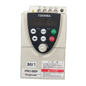
Toshiba
Toshiba TOSVERT VF-nC1 instruction manual

Selectronic Australia
Selectronic Australia SE10 operating manual
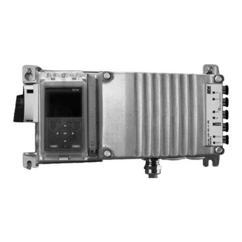
SEW-Eurodrive
SEW-Eurodrive MOVIMOT flexible MMF C/DSI Series operating instructions

DASS Tech
DASS Tech SOLEAF DSP-3320i-ODS Manual for use and installation

Telwin
Telwin TECNICA144-164 Troubleshooting and repair manual
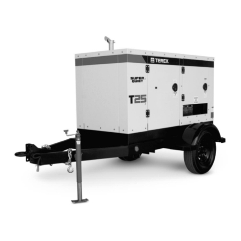
Terex
Terex T25 Service manual

