manuals.online logo
Brands
  1. Home
  2. •
  3. Brands
  4. •
  5. Heat & Glo
  6. •
  7. Gas Heater
  8. •
  9. Heat & Glo 6000XLSB Assembly instructions

Heat & Glo 6000XLSB Assembly instructions

This manual suits for next models

1

Other Heat & Glo Gas Heater manuals

Heat & Glo SL-750TRS-IPI-E User manual

Heat & Glo

Heat & Glo SL-750TRS-IPI-E User manual

Heat & Glo ST-HVBI-AU User manual

Heat & Glo

Heat & Glo ST-HVBI-AU User manual

Heat & Glo MISSION-BAY User manual

Heat & Glo

Heat & Glo MISSION-BAY User manual

Heat & Glo GRAND-I35 User manual

Heat & Glo

Heat & Glo GRAND-I35 User manual

Heat & Glo TIARAI-BK-C User manual

Heat & Glo

Heat & Glo TIARAI-BK-C User manual

Heat & Glo GRL-850-AU User manual

Heat & Glo

Heat & Glo GRL-850-AU User manual

Heat & Glo 350TRSI-AUF User manual

Heat & Glo

Heat & Glo 350TRSI-AUF User manual

Heat & Glo T-HVBI-AUB User manual

Heat & Glo

Heat & Glo T-HVBI-AUB User manual

Heat & Glo ST-HVBI-AU User manual

Heat & Glo

Heat & Glo ST-HVBI-AU User manual

Heat & Glo MEZZO 1000-AUB User manual

Heat & Glo

Heat & Glo MEZZO 1000-AUB User manual

Heat & Glo Heat & Glo TIARAII-BK-B User manual

Heat & Glo

Heat & Glo Heat & Glo TIARAII-BK-B User manual

Popular Gas Heater manuals by other brands

Superior BGE18NV Installation and operation instructions

Superior

Superior BGE18NV Installation and operation instructions

Dru Room-sealed atmospheric gas-fired heating... user manual

Dru

Dru Room-sealed atmospheric gas-fired heating... user manual

klover TKR 35 user guide

klover

klover TKR 35 user guide

Rothenberger Industrial 035984 instruction manual

Rothenberger Industrial

Rothenberger Industrial 035984 instruction manual

New Buck Corporation 34 user manual

New Buck Corporation

New Buck Corporation 34 user manual

Hargrove Timberland Glow Operation and installation guide

Hargrove

Hargrove Timberland Glow Operation and installation guide

Kinder Cameo BF Installation and maintenance instructions

Kinder

Kinder Cameo BF Installation and maintenance instructions

Qlima GH 438 B-2 Directions for use

Qlima

Qlima GH 438 B-2 Directions for use

Desa 125-R owner's manual

Desa

Desa 125-R owner's manual

Gasmate AH100 Series instructions

Gasmate

Gasmate AH100 Series instructions

Medallion MBP20TLB OWNER'S OPERATION AND INSTALLATION MANUAL

Medallion

Medallion MBP20TLB OWNER'S OPERATION AND INSTALLATION MANUAL

Clarke DEVIL 910SS User instructions

Clarke

Clarke DEVIL 910SS User instructions

Brant Radiant Heaters QTD Series User instruction

Brant Radiant Heaters

Brant Radiant Heaters QTD Series User instruction

L.B. White Therma Grow HW220 Owner's manual and instructions

L.B. White

L.B. White Therma Grow HW220 Owner's manual and instructions

Sealey LP35.V5 instructions

Sealey

Sealey LP35.V5 instructions

Italkero Falo Evo User manual and assembly instructions

Italkero

Italkero Falo Evo User manual and assembly instructions

Desa 30LP owner's manual

Desa

Desa 30LP owner's manual

Williams 2509822A owner's manual

Williams

Williams 2509822A owner's manual

manuals.online logo
manuals.online logoBrands
  • About & Mission
  • Contact us
  • Privacy Policy
  • Terms and Conditions

Copyright 2025 Manuals.Online. All Rights Reserved.

1
- Do not store or use gasoline or other flam-
mable vapors and liquids in the vicinity of this
or any other appliance.
-What to do if you smell gas
 Do not try to light any appliance.
 Do not touch any electrical switch.
 Do not use any phone in your building.
 Immediately call your gas supplier from a
neighbor's phone. Follow the gas supplier's
instructions.
 If you cannot reach your gas supplier, call
the fire department.
- Installation and service must be performed by a
qualified installer, service agency, or the gas
supplier.
Models:
7000XLS
6000XLSB
Installers Guide
WARNING: IMPROPER INSTALLA-
TION, ADJUSTMENT, ALTERATION,
SERVICE OR MAINTENANCE CAN
CAUSE INJURY OR PROPERTY DAM-
AGE. REFER TO THIS MANUAL. FOR
ASSISTANCE OR ADDITIONAL INFOR-
MATION CONSULT A QUALIFIED IN-
STALLER, SERVICE AGENCY, OR THE
GAS SUPPLIER.
Underwriters
Laboratories Listed
390-900F 9/00
READ THIS MANUAL BEFORE INSTALLING OR
OPERATING THIS APPLIANCE. THIS INSTALLERS
GUIDE MUST BE LEFT WITH APPLIANCE FOR
FUTURE REFERENCE.
1. This appliance may be installed in an af-
termarket, permanently located, manufac-
tured (mobile) home, where not prohibited
by local codes.
2. This appliance is only for use with the type
of gas indicated on the rating plate. This
appliance is not convertible for use with
other gases, unless a certified kit is used.
Please contact your Heat-N-Glo dealer for any
questions or concerns. For the number of your
nearest Heat-N-Glo dealer, please call 952-985-6000.
Printed in U.S.A. Copyright 2000,
Heat-N-Glo, a division of Hearth Technologies Inc.
20802 Kensington Boulevard, Lakeville, MN 55044
WARNING: IF THE INFORMATION
IN THESE INSTRUCTIONS IS NOT
FOLLOWED EXACTLY, A FIRE OR
EXPLOSION MAY RESULT CAUS-
ING PROPERTY DAMAGE, PER-
SONAL INJURY, OR DEATH.
This product is covered by one or more of the following patents: (United States) 4,112,913; 4,408,594; 4,422,426; 4,424,792; 4,520,791; 4,793,322;
4,852,548; 4,875,464; 5,000,162; 5,016,609; 5,076,254 5,191,877; 5,218,953; 5,328,356; 5,429,495; 5,452,708; 5,542,407; 5,613,487; (Australia)
543790; 586383; (Canada) 1,123,296; 1,297,746; 2,195,264; (Mexico) 97-0457; (New Zealand) 200265; or other U.S. and foreign patents pending.
2
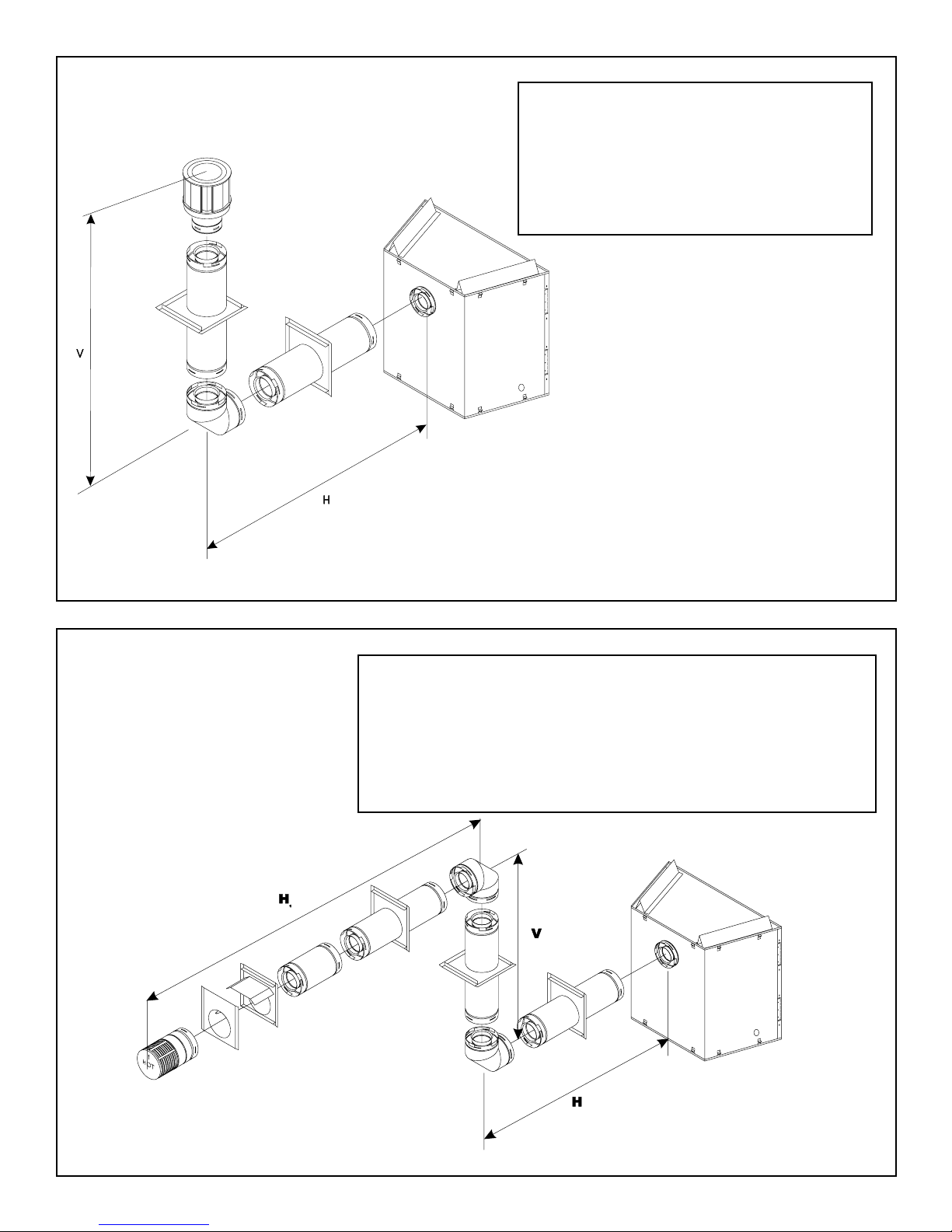
These units MUST use one of the vent systems
described in the Installing the Fireplace section of
the Installers Guide. NO OTHER vent systems or
components MAY BE USED.
This gas fireplace and vent assembly MUST be
vented directly to the outside and MUST NEVER be
attached to a chimney serving a separate solid fuel
burning appliance. Each gas appliance MUST USE
a separate vent system. Common vent systems are
PROHIBITED.
INSPECT the external vent cap on a regular basis to
make sure that no debris is interfering with the air
flow.
The glass door assembly MUST be in place and
sealed, and the trim door assembly MUST be in
place on the fireplace before the unit can be placed
into safe operation.
DO NOT OPERATE this appliance with the glass
door removed, cracked, or broken. Replacement of
the glass door should be performed by a licensed
or qualified service person. DO NOT strike or slam
the glass door.
The glass door assembly SHALL ONLY be
replaced as a complete unit, as supplied by the gas
fireplace manufacturer. NO SUBSTITUTE material
may be used.
DO NOT USE abrasive cleaners on the glass door
assembly. DO NOT ATTEMPT to clean the glass
door when it is hot.
Turn off the gas before servicing this appliance. It is
recommended that a qualified service technician
perform an appliance check-up at the beginning of
each heating season.
Any safety screen or guard removed for servicing
must be replaced before operating this appliance.
READ and UNDERSTAND all instructions carefully
before starting the installation. FAILURE TO
FOLLOW these installation instructions may result
in a possible fire hazard and will void the warranty.
Prior to the first firing of the fireplace, READ the
Using Your Fireplace section of the Owners Guide.
DO NOT USE this appliance if any part has been
under water. Immediately CALL a qualified service
technician to inspect the unit and to replace any part
of the control system and any gas control which has
been under water.
THIS UNIT IS NOT FOR USE WITH SOLID FUEL.
Installation and repair should be PERFORMED by a
qualified service person. The appliance and venting
system should be INSPECTED before initial use
and at least annually by a professional service
person. More frequent cleaning may be required
due to excessive lint from carpeting, bedding
material, etc. It is IMPERATIVE that the units
control compartment, burners, and circulating air
passageways BE KEPT CLEAN to provide for
adequate combustion and ventilation air.
Always KEEP the appliance clear and free from
combustible materials, gasoline, and other
flammable vapors and liquids.
NEVER OBSTRUCT the flow of combustion and
ventilation air. Keep the front of the appliance
CLEAR of all obstacles and materials for servicing
and proper operations.
Due to the high temperature, the appliance should
be LOCATED out of traffic areas and away from
furniture and draperies. Clothing or flammable
material SHOULD NOT BE PLACED on or near the
appliance.
Children and adults should be ALERTED to the
hazards of high surface temperature and should
STAY AWAY to avoid burns or clothing ignition.
Young children should be CAREFULLY SUPERVISED
when they are in the same room as the appliance.
!
!
!
!
!
!
!
!!
!
!
!
!
!
!
!
!
SAFETY AND WARNING INFORMATION
!
3
TABLE OF CONTENTS
Safety and Warning Information ................................................ 2
Service Parts Lists ..................................................................... 4
Section 1: Approvals and Codes ............................................... 8
Approval Listings and Codes ........................................................ 8
Appliance Certification................................................................... 8
Installation Codes .......................................................................... 8
High Altitude Installations ............................................................... 8
Section 2: Getting Started ......................................................... 9
Introducing the Heat-N-Glo Gas Fireplaces .................................. 9
Pre-installation Preparation ........................................................... 9
Section 3: Installing the Fireplace ........................................... 11
Step 1 Locating the Fireplace .................................................. 11
Step 2 Framing the Fireplace................................................... 11
Step 3 Installing the Vent System ............................................ 13
A. Vent System Approvals ........................................... 13
B. Installing Vent Components .................................... 16
C. Vent Termination .................................................... 20
Step 4 Positioning, Leveling, and
Securing the Fireplace................................................. 23
Step 5 The Gas Control Systems ........................................... 23
Step 6 The Gas Supply Line ................................................... 24
Step 7 Gas Pressure Requirements ...................................... 24
Step 8 Wiring the Fireplace .................................................... 25
Step 9 Finishing ...................................................................... 26
Step 10 Installing Trim, Logs, and Ember Material ..................... 27
Installing the Trim ......................................................... 27
Positioning the Logs .................................................... 27
Placing the Ember Material .......................................... 27
Step 11 Before Lighting the Fireplace ....................................... 28
Step 12 Lighting the Fireplace .................................................. 28
After the Installation ..................................................................... 28
Section 4: Maintaining and Servicing Your Fireplace ......... 29
u= Contains updated information.
u
u
u
8
Appliance Certification
The Heat-N-Glo fireplace models discussed in this Installers
Guide have been tested to certification standards and listed
by the applicable laboratories.
Certification
MODELS: 7000XLS, 6000XLSB
LABORATORY: Underwriters Laboratories
TYPE: Direct Vent Gas Fireplace Heaters
STANDARD: ANSI Z21.88CSA2.33
Installation Codes
The fireplace installation must conform to local codes. Before
installing the fireplace, consult the local building code
agency to ensure that you are in compliance with all
applicable codes, including permits and inspections.
In the absence of local codes, the fireplace installation must
conform to the National Fuel Gas Code ANSI Z223.1 (in
the United States) or the CAN/CGA-B149 Installation Codes
(in Canada). The appliance must be electrically grounded
in accordance with local codes or, in the absence of local
codes with the National Electric Code ANSI/NFPA No. 70
(in the United States), or to the CSAC22.1 Canadian Electric
Code (in Canada).
These models may be installed in a bedroom or bed-sitting
room in the U.S.A. and Canada.
1Approvals and
Codes
High Altitude Installations
U.L. Listed gas fireplaces are tested and approved for
elevations from 0 to 2,000 feet in the U.S.A. and from 0 to
4,500 feet in Canada.
When installing this fireplace at an elevation above 2,000
feet (in the United States), it may be necessary to decrease
the input rating by changing the existing burner orifice to a
smaller size. Input should be reduced four percent (4%) for
each 1,000 feet above sea level, unless the heating value of
the gas has been reduced, in which case this general rule
will not apply. To identify the proper orifice size, check with
the local gas utility.
When installing this fireplace at an elevation between 2,000
and 4,500 feet (in Canada), the input rating must be reduced
by ten percent (10%).
When installing this fireplace at an elevation above 4,500
feet (in Canada), check with local authorities.
Consult your local gas utility for assistance in determining
the proper orifice for your location.
Heat-N-Glo Quality
Systems registered
by SGS ICS
9
2Getting Started
Introducing the Heat-N-Glo Gas Fireplaces
Heat-N-Glo direct vent gas fireplaces are designed to oper-
ate with all combustion air siphoned from outside of the
building and all exhaust gases expelled to the outside.
The information contained in this Installers Guide, unless
noted otherwise, applies to all models and gas control
systems. Gas fireplace diagrams, including the dimensions,
are shown in this section.
Pre-install Preparation
This gas fireplace and its components are tested and safe
when installed in accordance with this Installers Guide.
Report to your dealer any parts damaged in shipment,
particularly the condition of the glass. Do not install any
unit with damaged, incomplete, or substitute parts.
The vent system components and trim doors are shipped
in separate packages. The gas logs may be packaged
separately and must be field installed.
Read all of the instructions before starting the
installation. Follow these instructions carefully during
the installation to ensure maximum safety and benefit.
Failure to follow these instructions will void the
owners warranty and may present a fire hazard.
The Heat-N-Glo Warranty will be voided by, and Heat-N-Glo
disclaims any responsibility for, the following actions:
 Installation of any damaged fireplace or vent system
component.
 Modification of the fireplace or direct vent system.
 Installation other than as instructed by Heat-N-Glo.
 Improper positioning of the gas logs or the glass door.
 Installation and/or use of any component part not manu-
factured and approved by Heat-N-Glo, not withstanding
any independent testing laboratory or other party approval
of such component part or accessory.
ANY SUCH ACTION MAY POSSIBLY CAUSE A FIRE
HAZARD.
When planning a fireplace installation, its necessary to
determine:
Where the unit is to be installed.
The vent system configuration to be used.
Gas supply piping.
Electrical wiring.
Framing and finishing details.
Whether optional accessoriesdevices such as a fan,
wall switch, or remote controlare desired.
If the fireplace is to be installed on carpeting or tile, or on
any combustible material other than wood flooring, the
fireplace should be installed on a metal or wood panel that
extends the full width and depth of the fireplace.
10
Figure 1. Diagram of the 7000XLS and 6000XLSB
11
3Installing the Fireplace
Step 1. Locating the Fireplace
The diagram below shows space and clearance require-
ments for locating a fireplace within a room.
ABCD E
42 22 36 51 72
Minimum Clearances
from the Fireplace to Combustible Materials
Inches mm
Glass Front........................ 36 .................... 914
Floor ................................... 0 ....................... 0
Rear ...................................1/2 ..................... 13
Sides .................................1/2 ..................... 13
Top ................................... 3 1/2 ................... 89
Ceiling* .............................. 31 .................... 787
Figure 2. Fireplace Dimensions, Locations,
and Space Requirements
Clearance Requirements
The top, back, and sides of the fireplace are defined by
stand-offs. The minimum clearance to a perpendicular wall
extending past the face of the fireplace is one inch (25 mm).
The back of the fireplace may be recessed 21 1/2 inches
(546 mm) into combustible construction.
Framing should be
constructed of 2 X 4
lumber or heavier.
A. ............... 42
B. ......... 38 1/2
C. ............... 22
D. ......... 25 5/8
Figure 3. Framing Dimensions
For minimum clearances, see the direct vent termination
clearance diagrams on pages 19 and 20 in this manual.
Step 2. Framing the Fireplace
Fireplace framing can be built before or after the fireplace is
set in place. Framing should be positioned to accommo-
date wall coverings and fireplace facing material. The dia-
gram below shows framing reference dimensions.
CAUTION: MEASURE FIREPLACE DIMENSIONS AND
VERIFY FRAMING METHODS AND WALL COVERING
DETAILS BEFORE FRAMING.
Minimum Clearances
from the Vent Pipe to Combustible Materials
Inches mm
Vertical Sections. ............. 1 ................ 25
Horizontal Sections
Top ..................................... 3 ................ 75
Bottom ............................... 1 ................ 25
Sides ................................. 1 ................ 25
At Wall Firestops
Top .................................. 2 1/2 ............ 63.7
Bottom .............................. 1/2 ............... 13
Sides ................................. 1 ................ 25
* The clearance to the ceiling is measured from the top
of the unit, excluding the standoffs (see Figure 28).
Shows center of 12 x 12 vent
framing hole for rear venting.
The center of the hole is one
inch (25.4mm) above the center
of the horizontal vent pipe.
A
B
C
The distance from the unit to combustible construction is to
be measured from the unit outer wrap surface to the com-
bustible construction, NOT from the screw heads that se-
cure the unit together.
12
Figure 4. D-Series Direct Vent Component Specifications
(5-inch inner pipe / 8 5/8-inch outer pipe)
NOTE: PIPES OVERLAP 1-3/8 INCHES (34.93mm)
AT EACH JOINT.
DV-36D
5 3/4”
(146mm)
8 3/4”
(222mm)
11 3/4”
(298mm)
DV-12D DV-09D DV-06D
DV-48D
DV-90D
73/8”
(187mm)
65/32”
(156mm)
115/8”
(295mm)
1115/16”
(303mm)
57/8”
(149mm)
8 5/8”
(220mm)
81/2”
(216mm)
67/16”
(164mm)
DV-45D
111/16”
(281mm)61/2”
(165mm)
81/2”
(216mm)
51/16”
(129mm)
85/8”
(220mm)
35 3/4”
(908mm)
47 3/4”
(1.2m)
13
HORIZONTAL VENTING
Kit No. H Max. Run
DVK-01D
DVK-01TRD 24" (610 mm)
NOTE: 7000XLS & 6000XLSB models are not approved to
use 45° elbows in corner installations. Use 90° elbows.
Figure 6. Corner Installation
Figure 5. Vent System Components and Termination Kits
Step 3. Installing the Vent System
A. Vent System Approvals
These models are approved to use D-series direct vent pipe
components and terminations (see Figures 4 and 5). Ap-
proved vent system components are labeled for identifica-
tion. This pipe is tested and listed as an approved compo-
nent of the fireplace. The pipe is tested to be run inside an
enclosed wall. There is no requirement for inspection open-
ings at each joint within the wall. There is no required pitch
for horizontal vent runs. NO OTHER VENTING SYSTEMS
OR COMPONENTS MAY BE USED.
Detailed installation instructions are included with each vent
termination kit and should be used in conjunction with this
Installers Guide.
The flame and ember appearance may vary based on the type
of fuel burned and the venting configuration used.
Identifying Vent Components
The vent systems installed on this gas fireplace may in-
clude one, two, or three 90° elbow assemblies. The rela-
tionships of vertical rise to horizontal run in vent configura-
tions using 90° elbows MUST BE strictly adhered to. The
rise to run relationships are shown in the venting drawings
and tables. Refer to the diagrams on the next several pages.
NOTE: Two 45° elbows may be used in place of one
90° elbow. Rise to run ratios in the vent system must
be followed if 45° elbows are used.
HORIZONTAL
TERMINATION
WALL FIRESTOP
90 DEGREE
ELBOW
VERTICAL
TERMINATION STORM COLLAR
ROOF FLASHING
HORIZONTAL PIPE
SUPPORT
PIPE LENGTH
WALL BRACKET
CEILING
FIRESTOP
DVK-01D DVK-TVCD
DVK-01TRD
Terminations Kits
45-DEGREE
ELBOW
90-DEGREE
ELBOWS
H
14
V H
1' MIN. (305mm) 2' MAX. (610mm)
2' MIN. (610mm) 4' MAX. (1.22m)
3' MIN. (914mm) 6' MAX. (1.86m)
4' MIN. (1.22m) 8' MAX. (2.4m)
V+H=40' MAX. (12.4m) H = 8' MAX. (2.4m)
NOTE: On vertical venting configurations
where the vertical component is over 10
feet, you may want to install the vertical
baffle included in the manual bag assembly
to improve flame appearance.
Figure 7. Venting with One 90° Elbow
VENTING WITH ONE (1) 90° ELBOW
Figure 8. Venting with Two 90° Elbows
VENTING WITH TWO (2)
90° ELBOWS V H H + H1
1´ MIN. (305 mm) 2´ MAX. (610 mm) 6´ MAX. (1.82m)
2´ MIN. (610 mm) 4´ MAX. (1.22 m) 12´ MAX. (3.65m)
3´ MIN. (914 mm) 6´ MAX. (1.86 m) 18´ MAX. (5.48m)
4´ MIN. (1.22 m) 8´ MAX. (2.48 m) 24´ MAX. (7.31m)
V+H+H
1
= 40´ MAX. (12.4 m) H = 8´ MAX. (2.48 m) H+H
1
= 24´ MAX. (7.31m)