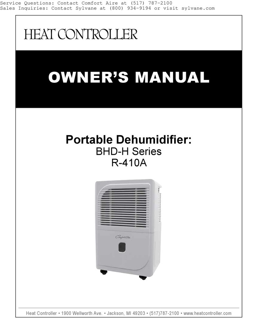
Heat Controller HFC Refrigerant R410a User manual

Heat Controller, Inc. • 1900 Wellworth Ave. • Jackson, MI 49203 • (517)787-2100 • www.heatcontroller.com
OWNER’S MANUAL
Portable Dehumidier:
BHD-G Series
R-410A
Beforeoperatingthisproduct,pleasereadtheinstructions
carefullyandsavethismanualforfutureuse.
DEHUMIDIFIER

Owner’s Manual BHD-G Portable Dehumidier Heat Controller, Inc.
1
1
CONTENTS
SAFETY PRECAUTIONS
Warning ..........................................................................................................................................2
Caution ...........................................................................................................................................2
Electrical information ......................................................................................................................3
OPERATIING THE UNIT
When using the unit .......................................................................................................................7
Removing the collected water ........................................................................................................8
CARE AND MAINTENANCE
Care and cleaning the dehumidifier ...............................................................................................9
TROUBLESHOOTING TIPS
Troubleshooting tips .....................................................................................................................10
CONTROL PADS ON THE DEHUMIDIFIER
Control pads....................................................................................................................................4
Other features................................................................................................................. ...............5
IDENTIFICATION OF PARTS
Identification of parts ......................................................................................................................6
Positioning the unit .........................................................................................................................7
CONTROL PANEL
Control panel

Heat Controller, Inc. BHD-G Portable Dehumidier Owner’s Manual
2
2
heat
generation.
excess
shock.
injury.
.
Y
yourself.
conditioner .
unit.
!
!
S A F E T Y P R E C A U T I O N S
!
CAUTION
unit.
W
.
fire.
!
T
.
.
CAUTION
.
WARNING
WARNING
Do not use a damaged or
unspecied power cord.
Always use a certied
servicer for repairs
Disconnect the power if
strange sounds, odors or
smoke comes from unit.

Owner’s Manual BHD-G Portable Dehumidier Heat Controller, Inc.
3
3
A
.
handled.
.
Y.
!
!
securely
!
CAUTION
!
T
The
Y
receptacle.
However
T
unit.
S A F E T Y P R E C A U T I O N S
Do not obstruct the intake or
exhaust openings
Before the unit is cleaned,
switch off power and turn off
the circuit breaker
dehumidier
dehumidier
type
NOTE: The illustration is for explanation
purposes only. The actual shape of the
plug and wall outlet may be different.
This unit is grounded through the
power cord plug when plugged
into a matching wall outlet.
Do not, under any
circumstances, cut,
remove, or bypass
the grounding prong.

Heat Controller, Inc. BHD-G Portable Dehumidier Owner’s Manual
4
C O N T R O L PANEL
12 3 6
5
Continuous
indicator
light
1
f.
2
3
Fig.1
P O W E R
C H E C K
F I L T E R F U L L C O N T I N U EP O W E R T U R B O T I M E R
O N O F F
Tf
4
the The
operation. T
f.
4
7
Whe o us h utto hange
operatio odes h ni il ake
ee oun ndicat ha s
changin odes.
Auto
Control Buttons
button
hours.
Control Buttons
NOTE: The control panel of the unit your purchased may be slightly different according
to the specific model. See Fig. 1.
or
The Rh (relative humidity) level can be
set within a range of 35-85% RH in 5%
increments. For drier air, lower the % RH
set point by pressing the key pad. For
damper air, raise the % RH set point by
pressing the key pad. When the % RH
set point is between 35-85% RH the unit
will operate the compressor and fan
together when the room’s % RH level is
5% higher than the % RH set point, until
the set % RH is achieved in the room.
Once the room’s % RH level becomes
less than the % RH set point, the
compressor will turn off and the fan will
run for another 3 minutes before turning
off. This cycle will continue in order to
maintain the humidity level of air in
relation to the % RH set point.
To run the unit in continuous mode,
press the key pad until the display
reads 35% RH. Then press the key pad
again until the display reads “CO” for
continuous operation. The continuous
operation indicator light will turn on. This
allows the compressor and fan to run
continuously at all times to constantly
dehumidify the room. To stop continuous
operation, press the key pad and set
the desired % RH set point level to
resume nominal operation.
Continuous Operation

Owner’s Manual BHD-G Portable Dehumidier Heat Controller, Inc.
5
C O N T R O L P A D S O N T H E D E H U M I D I F I E R
Ih as owe utag nterruption he
uni il utomaticall e-start hetting ast
used fte h owe estored.
Whe h ni nres he Timer
button he TIME F ndicato ight
illuminates ndicate he Aut top
progra nitiated.
Pres ol h o
chang he im .ou ncre-
ments ours he our
increment ours. Th ontrol
wil ount dow h im emainin ntil
start.
Whe he Aut tar Aut to ime re
set ithi h am rogra equence,
TIME F ndicato ight lluminate
identifyin ot n F ime re
no rogrammed.
Turnin h
ni Fn im r
adjustin hime ettin .il ancel
the Auto Start/Sto unction.
Whe hni ff res he Timer
button he TIME ndicato ight
illuminates ndicate he Aut tart
progra nitiated.
7
Display
- T
defrost.
30%
AS
ES
P1
P2
CO
5
6
buttons
y 0
The selected time will register in 5 seconds
and the system will automatically revert the
display back to the previous humidity setting.
When the LED display window displays the
code for P2, the Auto Start/Stop function
will also be cancelled.
Check filter feature
After 250 hours of accumulated fan motor
operation, the check filter light will flash to
indicate that the filter requires cleaning. Once
the filter is cleaned and returned to the unit,
press the key pad to stop the check filter
light from flashing.
Press to select either High or Normal fan speed. Set the fan
control to High for maximum moisture removal. When the
humidity has been reduced and quieter operation is preferred,
set the fan control to Normal.
dehumidification
when operating.
programming
Bucket is full or needs to be properly positioned
inside the cabinet.
4
C O N T R O L P A D S O N T H E D E H U M I D I F I E R
5
Glow he hucke ead e
emptied he h ucke emoved
ooeplace h rope osition.
Th ate eve ontro witc hut f he
dehumidifie he h ucke ull hen
th ucke emove o eplace he
prope osition he h ettin umidity
ieached hni il hu futomatically.
Whe ros uild hvaporato oils he
compresso il ycl fn h a il ontinue
tu nti h ros isappears.
Ih
as owe utag nterruption he
uni il utomaticall e-start h etting ast
used fte h owe estored.
Whe hni n res he Timer
button he TIME F ndicato ight
illuminates ndicate he Aut top
progra nitiated.
Pres ol h P o OW o
chang he im . ou ncre-
ments ours he our
increment ours. Th ontrol
wil ount dow h im emainin ntil
start.
Whe he Aut tar Aut to ime re
set ithi ham rogra equence,
TIME F ndicato ight lluminate
identifyin ot n Fime re
no rogrammed.
Turnin h ni F n im r
adjustin h ime ettin . il ancel
the Auto Start/Sto unction.
Whe h ni ff res he Timer
button he TIME ndicato ight
illuminates ndicate he Aut tart
progra
nitiated.
7
Display
- T
defrost.
30%
AS
ES
P1
P2
CO
5
6
Other Features
buttons
y 0
The selected time will register in 5 seconds
and the system will automatically revert the
display back to the previous humidity setting.
When the LED display window displays the
code for P2, the Auto Start/Stop function
will also be cancelled.
Check filter feature
The system starts to count the time once the fan
motor operates. The check filter feature can be
only activated when the accumulated operation
time achieves 250 hours or more. The CHECK
FILTER indicator light flashes at 1Hz. After the
air filter has been cleaned, replace it in the unit
and press the button and the CHECK
FILTER indicator light goes off.
Press to select either High or Normal fan speed. Set the fan
control to High for maximum moisture removal. When the
humidity has been reduced and quieter operation is preferred,
set the fan control to Normal.
dehumidification
when operating.
programming
Auto Shut Off
1. When the bucket is full, the water level control switch
removed or is not positioned properly, the unit will shut
off automatically. Also, ‘P2’ will be on the display and/or
the bucket full indicator light will be on to inform the user
that the bucket is full, is removed from the unit, or is not
positioned correctly inside the unit.
2. The compressor also has a auto shut off feature, which
is activated when the set relative humidity level is ob
-
tained. The compressor also has a 3 minute time delay
before it turns on, in order to protect itself when being
turned back on after being shut off or because of power
failure to the unit.
Auto Defrost
4
C O N T R O L P A D S O N T H E D E H U M I D I F I E R
5
Glow he hucke ead e
emptied he h ucke emoved
ooeplace h rope osition.
Th ate eve ontro witc hut f he
dehumidifie he h ucke ull hen
th ucke emove o eplace he
prope osition he h ettin umidity
ieached hni il hu futomatically.
Whe ros uild hvaporato oils he
compresso il ycl fn h a il ontinue
tu nti h ros isappears.
Ih
as owe utag nterruption he
uni il utomaticall e-start h etting ast
used fte h owe estored.
Whe hni n res he Timer
button he TIME F ndicato ight
illuminates ndicate he Aut top
progra nitiated.
Pres ol h P o OW o
chang he im . ou ncre-
ments ours he our
increment ours. Th ontrol
wil ount dow h im emainin ntil
start.
Whe he Aut tar Aut to ime re
set ithi h am rogra equence,
TIME F ndicato ight lluminate
identifyin ot n Fime re
no rogrammed.
Turnin h ni F n im r
adjustin h ime ettin . il ancel
the Auto Start/Sto unction.
Whe h ni ff res he Timer
button he TIME ndicato ight
illuminates ndicate he Aut tart
progra
nitiated.
7
Display
- T
defrost.
30%
AS
ES
P1
P2
CO
5
6
Other Features
buttons
y 0
The selected time will register in 5 seconds
and the system will automatically revert the
display back to the previous humidity setting.
When the LED display window displays the
code for P2, the Auto Start/Stop function
will also be cancelled.
Check filter feature
The system starts to count the time once the fan
motor operates. The check filter feature can be
only activated when the accumulated operation
time achieves 250 hours or more. The CHECK
FILTER indicator light flashes at 1Hz. After the
air filter has been cleaned, replace it in the unit
and press the button and the CHECK
FILTER indicator light goes off.
Press to select either High or Normal fan speed. Set the fan
control to High for maximum moisture removal. When the
humidity has been reduced and quieter operation is preferred,
set the fan control to Normal.
dehumidification
when operating.
programming
3 Minute Compressor Time Delay
After the unit has stopped, it can not be restarted within the
will automatically start after 3 minutes. If the compressor
was interrupted during operation, it can not be stopped in
full of water, defrosting or power failure modes.
Power Outage – Auto Restart Feature
Setting the Timer
Bucket Full Light
Shows the set % humidity level from 35% to 85% or
auto start/stop time (0~24 hrs.) while programming,
then shows the actual (+5% accuracy) room % humidity
level in a range of 30% RH (Relative Humidity) to 90%
RH when operating.

Heat Controller, Inc. BHD-G Portable Dehumidier Owner’s Manual
6
I D E N T I F I C A T I O N O F P A R T S
F r o n t
R e a r
Caster
Handle
W
W
1
2
3
4
5
6
1
2
3
4
5
1
2
3
4
5
Mo de l A
Mo de
1
2
3
4
5
Model A Mode
1
2
3
4
5
6
1
2
3
4
5
6
NOTE: All the pictures in
the manual are for explana-
tion purposes only. The
actual shape of the unit you
purchased may be slightly
different, but the operations
and functions are the same.
ATTENTION
Accessing drain hose, fitting and (2) screws are located inside the bucket. On some models, the drain
fitting is placed inside the Styrofoam base packaging of the unit.
Locate and remove these items before operating the unit or dispose of packing materials.

O P E R A T I N G T H E U N I T
appliances.
connection.
.
.
.)
A
.
.
performance.
Fig.4a
NOTE:
Fig.4b
Adhesiv ape
a ground
installed otherwise
14 F and 95 F (5 C - 35 C).
OOO O
When removing the dehumidifier from its
packaging, you will find tape pasted on several
places of the unit (see Fig. 4b). It is for transpor-
tation purposes only, just remove tape before
using the unit.
Keep unit away from heat sources, such as clothes dryer,
heater or radiator.
Use the unit to prevent moisture damage anywhere books or
valuables are stored.
Use the dehumidifier in a basement to help prevent moisture
damage. NOTE: A dehumidifier operating in a basement will
have little or no effect in drying and adjacent enclosed storage
area, such as a closet, unless there is adequate circulation of
air in and out of those additional areas.
The dehumidifier must be operated in an enclosed area to be
most effective.
Close all doors, windows and other outside openings to the
room.
When Using The Unit
Positioning the Unit
41°F (5°C).
41°F (5°C)
Allow at least 8in. (20cm) of air space on all sides of the unit
16in.
(40cm)
or more
8in. (20cm) or more
80cm or more 8in.
(20cm) or more 8in. (20cm) or more
8in. (20cm) or more
Air intake
grille
Air outlet grille
Accessing drain hose, fitting and (2) screws are
located inside the bucket. On some models, the
drain fitting is placed inside the Styrofoam base
packaging of the unit.
Locate and remove these items before operating
the unit or dispose of packing materials.
Owner’s Manual BHD-G Portable Dehumidier Heat Controller, Inc.
7
7
OPERATING THE UNIT
Whenusingtheunit
Whenfirstusingthedehumidifier,operatetheunit
continuously24hours.
Thisunitisdesignedtooperatewithaworking
environmentbetween5 Cand35 C.
Iftheunithasbeenswitchedoffandneedstobe
switchedonagainquickly,allowapproximately
threeminutesforthecorrectoperationtoresume.
Donotconnectthedehumidifiertoamultiplesocket
outlet,whichisalsobeingusedforotherelectrical
appliances.
Selectasuitablelocation,makingsureyouhaveeasy
accesstoanelectricaloutlet.
Plugtheunitintoaelectricalsocket-outletwithearth
connection.
MakesuretheWaterbucketiscorrectlyfittedotherwise
theunitwillnotoperateproperly.
O O
Casters(Atfourpointsonthebottomofunit)
Casterscanmovefreely.
Donotforcecasterstomoveovercarpet,
normovetheunitwithwaterinthebucket.
(Theunitmaytipoverandspillwater.)
A dehumidifieroperatinginabasementwillhavelittleornoeffectindryinganadjacentenclosed
storagearea,suchasacloset,unlessthereisadequatecirculationofairinandoutofthearea.
Airoutletgrille
Airintake
grille
20cmormore
20cmormore 20cmormore
20cmormore
40cmor
more
Positioningtheunit
Donotuseoutdoors.
Thisdehumidiferisintendedforindoorresidential
applicationsonly. Thisdehumidifiershouldnotbeused
forcommercialorindustrialapplications.
Placethedehumidifieronasmooth,levelfloorstrong
enoughtosupporttheunitwithafullbucketofwater.
Allowatleast20cmofairspaceonallsidesoftheunit
forgoodaircirculation.
Placetheunitinanareawherethetemperaturewillnot
fallbelow5C(41F). Thecoilscanbecomecoveredwith
frostattemperaturesbelow5C(41F),whichmayreduce
performance.
Placetheunitawayfromtheclothesdryer,heaterorradiator.
Usetheunittopreventmoisturedamageanywherebooks
orvaluablesarestored.
Usethedehumidifierinabasementtohelpprevent
moisturedamage.
Thedehumidifiermustbeoperatedinanenclosed
areatobemosteffective.
Closealldoors,windowsandotheroutsideopenings
totheroom.
Fig.4a
Whenremovingthedehumidifierfromits
packaging,youwillfindplasticadhesivetapepasted
onseveralplacesoftheunit(seeFig.4b).Itisfor
transportationpurposeonly,justremovethembefore
youusingthedehumidifier.
NOTE:
Fig.4b
Adhesivetape

Heat Controller, Inc. BHD-G Portable Dehumidier Owner’s Manual
8
8
Removingthecollectedwater 1.Pulloutthebucketalittle.
2.Holdbothsidesofthebucket
withevenstrength,andpullit
outfromtheunit.
3.Pourthewaterout.
Therearetwowaystoremovecollectedwater.
1.Usethebucket
Whenthebucketisfull,theunitwillautomaticallystop
running,theunitwillbeep8timesandandtheFull
indicatorlightwillflash,thedigitaldisplayshowsP2.
Slowlypulloutthebucket.Griptheleftandright
handlessecurely,andcarefullypulloutstraightso
waterdoesnotspill.Donotputthetankonthefloor
becausethebottomofthebucketisuneven.Otherwise
thebucketwillfallandcausethewatertospill.
Throwawaythewaterandreplacethebucket. The
bucketmustbeinplaceandsecurelyseatedforthe
dehumidifiertooperate.
Themachinewillre-startwhenthebucketisrestored
initscorrectposition.
NOTES:
Whenyouremovethebucket,donottouchanyparts
insideoftheunit.Doingsomaydamagetheproduct.
Besuretopushthebucketgentlyallthewayintothe
unit.Bangingthebucketagainstanythingorfailingto
pushitinsecurelymaycausetheunitnottooperate.
Fig.5
Fig.6
Fig.7
OPERATING THE UNIT
NOTE: Whenthecontinuousdrainfeatureisnotbeing
used,removethedrainhosefromtheconnectorand
attachthebackdrainholewiththerubberplugshown
inFig.1.
2.Continuousdraining
Watercanbeautomaticallyemptiedintoafloor
drainbyattachingtheunitwithawaterhose
(O12mm)(notincluded).
Removethe
rubberplug
Pushthehose
intothedrain
hole
Fig.8
Connector
Fig.9
Drainhose
Removethewaterbucketfromthefrontofthe
unit,youwillfindasectionofhoselocated
abovethebucket.
Removetherubberplugfromthebackofthe
unit andstoreitinasafelocation(seeFig.8).
Insertthewaterhosethroughtheholeinthe
backoftheunitandsecurelypressitintothe
connectoronthefront oftheunit(Fig.9). Then
leadthewaterhosetothefloordrainorasuitable
drainagefacility.
Replacethebucketintheunit. Thebucketmust
beinplaceandsecurelyseated.
The unit will re-start when the bucket is restored
2. Hold both sides of the bucket
securely and pull it out from
the unit.
2. Continuous draining
Water can be automatically emptied into a oor drain by
attaching a standard garden water hose (o 0.5 in./
o 12mm, not included).
• Remove the water bucket from the front of the
unit, you will nd a section of hose located above
the bucket. Also, locate the tting and (2) screws
included, either inside the bucket and/or within the
Styrofoam base packing material.
• Remove the rubber plug from the back of the unit
and store it in a safe location (see Fig. 8).
• Insert the water hose through the hole in the back
of the unit and securely press it onto the connec-
tor on the front of the unit (Fig. 9). Next attach the
opposite end of the hose to the tting. Attach the
tting with (2) screws provided to the back of the
unit. Then lead the water hose to the oor drain or a
suitable drainage location.
• Replace the bucket in the unit. The bucket must be
in place and securely seated.
NOTE: When the continuous drain feature is not being used, remove the
drain hose from the connector as well as the tting and screws. Then at-
tach the rubber plug back over the drain hole as shown in Fig. 8.
8
Removingthecollectedwater 1.Pulloutthebucketalittle.
2.Holdbothsidesofthebucket
withevenstrength,andpullit
outfromtheunit.
3.Pourthewaterout.
Therearetwowaystoremovecollectedwater.
1.Usethebucket
Whenthebucketisfull,theunitwillautomaticallystop
running,theunitwillbeep8timesandandtheFull
indicatorlightwillflash,thedigitaldisplayshowsP2.
Slowlypulloutthebucket.Griptheleftandright
handlessecurely,andcarefullypulloutstraightso
waterdoesnotspill.Donotputthetankonthefloor
becausethebottomofthebucketisuneven.Otherwise
thebucketwillfallandcausethewatertospill.
Throwawaythewaterandreplacethebucket. The
bucketmustbeinplaceandsecurelyseatedforthe
dehumidifiertooperate.
Themachinewillre-startwhenthebucketisrestored
initscorrectposition.
NOTES:
Whenyouremovethebucket,donottouchanyparts
insideoftheunit.Doingsomaydamagetheproduct.
Besuretopushthebucketgentlyallthewayintothe
unit.Bangingthebucketagainstanythingorfailingto
pushitinsecurelymaycausetheunitnottooperate.
Fig.5
Fig.6
Fig.7
OPERATING THE UNIT
NOTE: Whenthecontinuousdrainfeatureisnotbeing
used,removethedrainhosefromtheconnectorand
attachthebackdrainholewiththerubberplugshown
inFig.1.
2.Continuousdraining
Watercanbeautomaticallyemptiedintoafloor
drainbyattachingtheunitwithawaterhose
(O12mm)(notincluded).
Removethe
rubberplug
Pushthehose
intothedrain
hole
Fig.8
Connector
Fig.9
Drainhose
Removethewaterbucketfromthefrontofthe
unit,youwillfindasectionofhoselocated
abovethebucket.
Removetherubberplugfromthebackofthe
unit andstoreitinasafelocation(seeFig.8).
Insertthewaterhosethroughtheholeinthe
backoftheunitandsecurelypressitintothe
connectoronthefront oftheunit(Fig.9). Then
leadthewaterhosetothefloordrainorasuitable
drainagefacility.
Replacethebucketintheunit. Thebucketmust
beinplaceandsecurelyseated.
• Accessory drain hose, tting and (2) screws are located inside bucket. On some models, the drain
tting is placed inside the Styrofoam base packaging of the Unit.
• Locate and remove these items before operating the unit or dispose of packaging materials.

Owner’s Manual BHD-G Portable Dehumidier Heat Controller, Inc.
9
9
3.Cleantheairfilter
Theairfilterbehindthefrontgrilleshouldbe
checkedandcleanedatleastevery30days
ormoreoftenifnecessary.
Gripthetabonthefilterandpullitoutasshown
inFig.11A.
Cleanthefilterwithwarm,soapywater.Rinseand
letthefilterdrybeforereplacingit.Donotcleanthe
filterinadishwasher.
Inserttheairfilterintotheunitfromthesideandpush
itin.SeeFig.11C
DONOT operatethedehumidifierwithoutafilter
becausedirtandlintwillclogitandreduce
performance.
NOTE:DONOTRINSEORPUTTHEFILTER
IN AN AUTOMATICDISHWASHER.
Toremove:
Toattach:
CAUTION:
Fig.11A
Fig.11B
Fig.11C
Afterturningofftheunit,waitonedaybeforeemptying
thebucket.
Cleanthemainunit,waterbucketandairfilter.
Wrapthecordandbundleitwiththeband.
Covertheunitwithaplasticbag.
Storetheunituprightinadry,well-ventilatedplace.
Band
Powercord
4.Whennotusingtheunitforlongtimeperiods
CARE AND MAINTENANCE
Careandcleaningof thedehumidifier
Turnthedehumidifieroff andremovetheplug
fromthewalloutletbeforecleaning.
1.CleantheGrilleandCase
Usewaterandamilddetergent.Donotusebleach
orabrasives.
Donotsplashwaterdirectlyontothemainunit.Doing
somaycauseanelectricalshock,causetheinsulation
todeteriorate,orcausetheunittorust.
Theairintakeandoutletgrillesgetsoiledeasily,souse
avacuumattachmentorbrushtoclean.
2.Cleanthebucket
Everyfewweeks,cleanthebuckettopreventgrowthofmold,
mildewandbacteria.Partiallyfillthebucketwithcleanwater
andaddalittlemilddetergent.Swishitaroundinthebucket,
emptyandrinse.
Donotuseadishwashertocleanthebucket.
Afterclean,thebucketmustbeinplaceandsecurely
seatedforthedehumidifiertooperate.
NOTE:
Thinner
No
Household
Drain
Cleaner
Fig.10
Fig.12
After cleaning, the bucket must be in place and securely
NOTE: DO NOT PUT THE FILTER
IN AN AUTOMATIC DISHWASHER.
4. When not using the unit for long periods of time

Heat Controller, Inc. BHD-G Portable Dehumidier Owner’s Manual
10
10
T R O U B L E S H O O T I N G T I P S
Problem
outlet.
W
.
closed
,
coils
W
ES, CONTROL
s
’
A
PANEL section
which will remove frost as needed
,
The unit is tilted instead of level or upright as it should be.
within the room the unit is operating in.
41°F (5°C).
.
.

04/2009
09/2011
Other manuals for HFC Refrigerant R410a
3
This manual suits for next models
1
Table of contents
Other Heat Controller Dehumidifier manuals
Heat Controller
Heat Controller Comfort-Aire BHD-301-C User manual
Heat Controller
Heat Controller BHD-301-G User manual

Heat Controller
Heat Controller BHD-501 User manual
Heat Controller
Heat Controller Comfort-aire BHD-301-D User manual
Heat Controller
Heat Controller BHD-301 User manual

Heat Controller
Heat Controller BHD-301 User manual

Heat Controller
Heat Controller Comfort-Aire BHD-501-D User manual
Heat Controller
Heat Controller BHD-H Series User manual

Heat Controller
Heat Controller BHD-301 User manual
Heat Controller
Heat Controller Comfort-Aire BHD-501-D User manual
