ecofort ecodry 925 User manual

Luftentfeuchter
Air dehumidier
Deumidicatore d’aria
Déshumidicateur d’air

2
M1290-0_draft-0

3
M1290-0_draft-0

DEUTSCH
4
M1290-0_draft-0
Wichtige Daten
Ecodry 925
Anhaltswert behandelbares Luftvolumen [m³] 600
Kondensationsleistung [L/24h] (*) 28,3 (**) 45,6
Betriebstemperaturen [°C] +2 / +32
Relative Luftfeuchtigkeit Gerätebetrieb 40 / 95
Luftdurchsatz [m³/h] 600
Speisespannung 230 V, 50 Hz
Stromaufnahme [A] (*) 3,05 (**) 3,45
Leistungsaufnahme [W] (*) 680 (**) 770
Leistungsaufnahme in Standby (Höchstwert) [W] 1,2
Refrigerating gas charge [g] siehe Aufkleber
Kühlmitteltyp R1234yf
Höchstdruck Kühlkreislauf [MPa] 2,6
Schallpegel in 1 m Abstand [dBa] 77
Abmessungen LxHxB [mm] 587×617×388
Leergewicht [Kg] 32,8
Fassungsvermögen Kondensatbehälter [L] 12
(*) bei 25°C und 65 %rel.LF (**) bei 30°C and 80% rel.LF
Die oben genannten Daten können sich ohne vorherige Ankündigung ändern.
Tab.A – Wichtige Daten
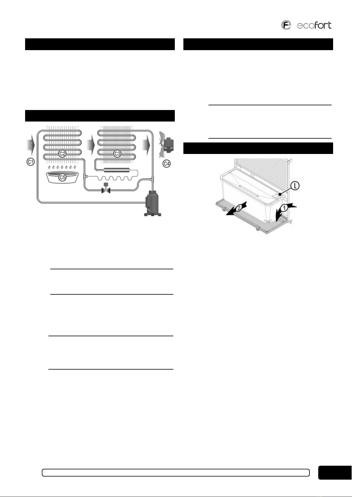
Legende und Symbole
BDieses Symbol weist darauf hin, dass das
Gerät mit entammbarem Kühlgas be-
füllt wurde.
DDieses Handbuch aufmerksam lesen.
ABedienerhandbuch, Anweisungen für
den Betrieb und die Normalwartung.
EACHTUNG: Diese Warnung weist auf
mögliche Gefahren oder Situationen hin,
die bei Nichtbeachtung der Anweisungen
zu Sach- und Personenschäden führen
können. Die Anweisungen müssen strikt
beachtet werden.
CBitte beachten: Die Hinweise weisen auf
Situationen und Bedingungen hin, die
den Gebrauch vom Gerät erleichtern und
verbessern können.
FGEFAHR, spannungsführende Elektro-
teile.
Allgemeine Sicherheitsvorschriften
DDieses Handbuch sorgfältig auewahren und
nachschlagen, denn alle enthaltenen Hinweise
liefern wichtige Angaben für die Sicherheit in
den Installations-, Gebrauchs- und Wartungs-
phasen.
BDieses Gerät enthält eine unter Druck stehen-
de entammbare Kühlüssigkeit: Jede War-
tung am Kühlkreislauf muss von einem Fach-
techniker durchgeführt werden, der über eine
gültige Zulassung durch eine akkreditierte
Stelle verfügt, die seine Fähigkeit bescheinigt,
mit dieser Art von Kühlmittel sicher umgehen
zu können.
• Die Kühlüssigkeit ist geruchlos: Falls eine Kühlgasleckage
befürchtet wird, ist vor irgendwelchen Eingrien der Raum
angemessen zu lüen.
• Das Gerät ist in einem Raum aufzustellen, in dem es KEINE
ständig in Funktion stehenden Zündquellen gibt (z.B.: oe-
ne Flammen, Elektro- oder Gasheizung).
• Der Entfeuchter ist NICHT für den Gebrauch durch Per-
sonen mit eingeschränkten körperlichen oder geistigen
Fähigkeiten gedacht, einschließlich Kinder, sowie für den
Gebrauch durch Personen, die nicht über ausreichende Er-
fahrung oder Kenntnisse verfügen, außer sie wurden von
einer Person, die für ihre Unversehrtheit verantwortlich ist,
in den korrekten Gebrauch des Geräts eingewiesen. Außer-
halb der Reichweite von Kindern und Tieren auewahren.
• Das Gerät darf nicht an explosionsgefährdeten Standorten
verwendet werden.
• Das Gerät darf nicht an Standorten verwendet werden, an
denen die Atmosphäre Öle, Sulde oder Chlor enthält.
• Die Gitter an den Lüungsönungen dürfen nicht verdeckt
werden (mindestens einen Abstand von 10 cm einhalten).
• Das Gerät darf nur benützt werden, wenn es aufrecht auf
seinen vier Rollen steht.
• Das Gerät bei Betrieb nicht bewegen.
• Um das Gerät zu verschieben oder an einen anderen Ort zu
bringen, das Gerät zuerst ausschalten und den Sammelbe-
hälter vom Kondensat leeren.
• Keine Gegenstände in das Gerät stecken.
• Weder durchstechen noch verbrennen.
FDieses Gerät ist an eine geerdete elektrische
Anlage anzuschließen. Sicherstellen, dass die
Anschlussspannung der in der Tab.A angege-
benen Spannung entspricht, dass die elektri-
sche Anlage die geltenden Vorschrien erfüllt
und angemessen geschützt ist.
• Das Gerät darf nur wie in diesem Handbuch beschrieben
benutzt werden. Jeder andere Gebrauch ist gefährlich und
kann Sach- und Personenschäden verursachen und ist des-
halb verboten.

DEUTSCH 5
M1290-0_draft-0
Allgemeine Informationen
Bei den Geräten der Serie Ecodry 925 handelt es sich um Lu-
entfeuchter, die den Zweck haben, der Umgebung unter Einsatz
eines Kühlkreislaufs Feuchtigkeit zu entziehen. Die neue elek-
tronische Steuerung steuert alle Funktionen vom Entfeuchter,
einschließlich vom automatischen Einschalten und Abschalten
sowie vom Abtauzyklus, falls erforderlich. Diese Geräte sind
für den Hausgebrauch bestimmt und eignen sich nicht für den
industriellen Einsatz.
Funktionsweise
Abb.1 – Die wichtigsten Bauteile
Die Lu (C1), die entfeuchtet werden soll, wird vom Gerät mit-
hilfe vom Gebläse (C4) angesaugt und durch den Verdampfer
(C2) vom Kühlkreislauf geleitet. Dadurch wird die Temperatur
der Lu unter den Taupunkt abgesenkt und der Wasserdampf
kondensiert zu Wassertropfen, die in dem dafür vorgesehenen
Sammelbehälter (C5) aufgefangen werden.
EDas Wasser im Sammelbehälter ist KEIN
Trinkwasser. Das Wasser aus dem Sammelbe-
hälter deshalb auf keinen Fall trinken.
Die entfeuchtete Lu wird durch den Kondensator (C3) gelei-
tet, wo ihre Temperatur auf einen Wert erhöht wird, der leicht
über der Ausgangstemperatur liegt. So wird die in der Umge-
bungslu enthaltene Feuchtigkeit nach und nach auf den ge-
wünschten Wert gesenkt.
CWenn ein Raum entfeuchtet wird, wird da-
durch auch die Feuchtigkeit in den Wänden
und dem Fußboden vom Raum sowie der darin
enthaltenen Materialien gesenkt.
Das heiße Gas Abtauzyklus
Wenn die Temperatur unter einen Wert von ca. 16°C fällt, kann
sich am Verdampfer (9) Eis bilden. Das Eis muss in regelmä-
ßigen Abständen entfernt werden, um zu verhindern, dass der
Lustrom unterbrochen wird. Die elektronische Karte steuert
den Abtauzyklus vollautomatisch (siehe unten). Während der
Abtauung die Fans C4 zu stoppen. Die Dauer vom Abtauzyklus
hängt von Feuchtigkeit und Temperatur ab.
BVerwenden Sie kein externes Werkzeug, um
den Abtauvorgang zu beschleunigen: Warten
Sie, bis die Abtauung durch die Luentfeuch-
tersteuerung abgeschlossen ist.
Das Reservoir
Abb.2 – Der Sammelbehälter
Der Sammelbehälter für das Kondenswasser bendet sich hin-
ter der vorderen Klappe und verfügt über einen Schwimmer,
der den Entfeuchter abschaltet, sobald der Behälter voll ist.
Leeren
Die Kappe önen und den Behälter herausnehmen (siehe
Abb.2). Das Wasser durch die Klappe L ausleeren. Dann den
Behälter wieder einsetzen und die Klappe schließen.
Endlos-Abuss
Der Kondensatbehälter ist auf einen Endlos-Abuss ausgelegt.
Der Anschluss ist ganz einfach. Sobald der Anschluss durchge-
führt worden ist, ist ein Ausleeren vom Kondensatbehälter von
Hand nicht mehr erforderlich. Den Endlos-Abuss wie folgt
installieren (siehe Abb.3):
• Den Deckel (T) abnehmen.
• Einen Schlauch Ø10 mm innen am Behälter anschließen
und durch die Önung (F) aus dem Entfeuchter herausfüh-
ren.
• Den Behälter in das Gerät einsetzen und dabei auf den Ab-
ussschlauch achten.

DEUTSCH
6
M1290-0_draft-0
Abb.3 – Endlos-Abuss
• Die Klappe schließen.
EACHTUNG: Damit das Gerät korrekt funktio-
niert, muss der Schlauch konstant nach unten
geführt werden und darf nicht verdreht oder
abgeklemmt werden. Der Schwimmer bleibt in
jedem Fall aktiviert und schaltet den Ent-
feuchter bei vollem Behälter ab.
Der Luftlter
Der Lulter bendet sich hinter dem vorderen Gitter vom
Entfeuchter und kann zur Reinigungszwecken einfach heraus-
genommen werden. Der Filter kann mit dem Staubsauger oder
mit Wasser gesäubert werden. Wenn der Filter ausgewaschen
wird, darf er erst dann wieder eingesetzt werden, wenn er ganz
trocken ist.
CDen Entfeuchter nicht ohne den Lulter
laufen lassen, das sich sonst Schmutz im
Wärmeaustauscher ansammelt. Den Lulter
häug sauber machen, vor allem an staubigen
Standorten. Wenn der Filter verschmutzt ist,
behindert er den Lustrom und reduziert die
Ezienz vom Luentfeuchter.
Ausbauen vom Luftlter
Abb.4 – Ausbauen vom Lulter
Um den Lulter herauszunehmen, das vordere Gitter nach
oben klappen und abnehmen (siehe Abb.4). Der Filter bendet
sich direkt hinter dem Gitter.
Einbauen vom Luftlter
Abb.5 – Einbauen vom Lulter
Den Filter am Gitter befestigen und die Rippen B in die Schlit-
ze F am Gehäuse stecken (siehe Abb.5). Dann das Gitter leicht
nach oben ziehen und am Bügel S festhaken.
Die Gerätesteuerung
Abb.6 – Die Gerätesteuerung
S1 - Grüne Kontrollleuchte Betrieb: Die Kontrollleuchte
schaltet sich ein, wenn der Entfeuchter läu, und blinkt, wenn
der Entfeuchter in Standby (0) ist (Strom ein, Entfeuchter aus).
S2 - Rote Kontrollleuchte Überlauf: Die Kontrollleuchte
schaltet sich ein und blinkt zusammen mit S1, wenn der Behäl-
ter voll ist, fehlt oder nicht korrekt eingesetzt wurde.
S3 - Gelbe Kontrollleuchte Abtauen: Die Kontrollleuchte
schaltet sich ein, wenn der Entfeuchter einen automatischen
Abtauzyklus durchführt.
T1 - Taste Verringern: Durch Drücken dieser Taste wird der
Wert, der auf dem Display D angezeigt wird, verkleinert (bis
Null).
T2 - Taste Erhöhen: Durch Drücken dieser Taste wird der
Wert, der auf dem Display D angezeigt wird, erhöht (bis C).
D - Display: Auf dem Display wird der Funktionsstatus vom
Entfeuchter angezeigt (siehe Tab.B unten). Der Wert 0 zeigt an,
dass das Gerät AUS ist. 1 bis 9 zeigen an, dass das Gerät im
Automatikbetrieb läu und vom Feuchtigkeitsregler gesteuert
wird, der den Entfeuchter je nach Lufeuchtigkeit (siehe Tab.A
unten) ein- und ausschaltet. Der Wert C zeigt an, dass das Ge-
rät im DAUERBETRIEB läu, unabhängig von der Lufeuch-
tigkeit. Eventuelle Alarme haben immer Priorität vor der ein-
gestellten Betriebsart.

DEUTSCH 7
M1290-0_draft-0
Display Betriebsart Display Betriebsart
0AUS 6 60% rel.LF
1 90% rel.LF 7 52% rel.LF
2 86% rel.LF 8 46% rel.LF
3 78% rel.LF 9 40% rel.LF
4 72% rel.LF C DAUERBETRIEB
5 65% rel.LF
Tab.B – Funktionsweise
Einschalten
Beim Einstecken vom Gerätestecker blinkt das Display D 5 Se-
kunden lang und zeigt dann den letzten Funktionsstatus vom
Entfeuchter an. Wenn die Betriebsart dann nicht Null ist, hört
das Display auf zu blinken.
Ausschalten
Zum Ausschalten vom Entfeuchter die Taste T1 drücken, bis
auf dem Display der Wert 0 angezeigt wird. Wenn die Betriebs-
art Null (Standby) gewählt wird, blinken die Kontrollleuchte
S1 und das Display D.
Abtauen
Die elektronische Karte steuert den Abtauzyklus automatisch
und entfernt regelmäßig das Eis, das sich am Wärmeaustau-
scher bildet. Dadurch ist immer für eine optimale Luzir-
kulation garantiert, auch bei niedrigeren Temperaturen. Das
Einschalten vom Abtauzyklus wird von der Kontrollleuchte S3
angezeigt.
Defekte
Auf dem Display werden neben dem Funktionsstatus vom Ent-
feuchter auch eventuelle Defekte (Tab.C) angezeigt. Sollte einer
der beschriebenen Fehler auauchen, ist eine Reparatur durch
Fachpersonal erforderlich.
Display Beschreibung
n Temperatursonde defekt oder abgelöst
u Feuchtigkeitssonde defekt oder abgelöst
Tab.C – Fehlermeldungen
Aufstellen
Abb.7 – Luzuführung und Luableitung
Die Entfeuchter dieser Serie werden ganz einfach in den Raum
gestellt, der entfeuchtet werden soll, und eingeschaltet.
EDas Gerät ist in einem Raum aufzustellen, in
dem es KEINE ständig in Funktion stehenden
Zündquellen gibt (z.B.: oene Flammen, Elek-
tro- oder Gasheizung).
Die Besonderheit dieser Entfeuchter ist es, dass sie die Lu
vorne ansaugen und die entfeuchtete Lu nach oben ausgeben
(siehe Abb.7). Deshalb kann der Entfeuchter auch zwischen
zwei Möbelstücken aufgestellt werden.
Damit das Gerät optimal funktioniert, müssen folgende Vor-
schrien beachtet werden:
• Sicherstellen, dass die Grenzwerte für den Gerätebetrieb
(Tab.A) am Gerätestandort nicht überschritten werden.
• Der Entfeuchter muss in einem geschlossenen Raum aufge-
stellt werden.
• Der Entfeuchter sollte an der kältesten Stelle im Raum auf-
gestellt werden, wo sich normalerweise die Feuchtigkeit an-
sammelt, und möglichst in der Nähe einer Steckdose.
EACHTUNG! Dieser Entfeuchter eignet sich
NICHT für Räumlichkeiten wie z.B. Wäsche-
reien oder ähnliches, an denen Wasserspritzer
oder Tropfwasser durch die obere Lüungsö-
nung in das Gerät eindringen können.
Wartung
Die Entfeuchter dieser Serie machen keine besondere Wartung
erforderlich. Sie sollten abgestaubt werden. Die Lüungsgitter
an der Ansaugönung und der Ausgabeönung regelmäßig
sauber machen. Bei Funktionsstörungen und Defekten bitte
den Händler kontaktieren.
BDieses Gerät enthält eine unter Druck stehen-
de entammbare Kühlüssigkeit: Jede War-
tung am Kühlkreislauf muss von einem Fach-
techniker durchgeführt werden, der über eine
gültige Zulassung durch eine akkreditierte
Stelle verfügt, die seine Fähigkeit bescheinigt,
mit dieser Art von Kühlmittel sicher umgehen
zu können.
Das Stromkabel hat einen Anschluss vom Typ M. Bei Beschä-
digung muss das Stromkabel von einem erfahrenen Elektriker
durch ein gleichwertiges Kabel ersetzt werden.
EBei Eingrien am elektrischen oder mecha-
nischen Teil ist die entammbare Kühlüs-
sigkeit zu berücksichtigen. Vor jedem Eingri
sicherstellen, dass alle möglichen Zündquellen
beseitigt wurden und prüfen, dass die Kon-
densatoren entleert sind, dass keine Teile
unter Spannung stehen und dass das Gerät
angemessen an Erde angeschlossen ist.
Die Kühlüssigkeit ist geruchlos: Falls eine Kühlgasleckage be-
fürchtet wird, ist vor irgendwelchen Eingrien der Raum an-
gemessen zu lüen.
EACHTUNG! Vor Durchführung von Eingrien
gleich welcher Art am Gerät den Stecker aus
der Steckdose ausstecken.

DEUTSCH
8
M1290-0_draft-0
Lagerung
• Das Gerät in einem geschlossenen Raum bei einer Tempe-
ratur zwischen -25°C und +55°C lagern.
• Wenn das Gerät noch verpackt ist, die Hinweise auf der Ver-
packung beachten.
• Keine schweren Gegenstände auf den Karton stellen, in dem
das Gerät verpackt ist.
Kontrollen vor und nach einer längeren
Außerbetriebnahme
Vorher
• Den Stecker aus der Steckdose ziehen und den Kondensat-
behälter ausleeren.
• Das Gerät zum Schutz vor Staub abdecken.
Nachher
• Das Gebläse muss sich frei und ohne Reibung drehen.
• Das Gerät einschalten und dazu die Anweisungen in diesem
Handbuch beachten.
Entsorgung von Gerät
INFORMATION FÜR DIE BENUTZER
Nur für EU-Mitgliedsstaaten
Das Symbol mit der durchgestrichenen Abfalltonne bedeutet,
dass das Produkt nach seiner Aussonderung vom restlichen
Müll getrennt entsorgt werden muss. Der Benutzer muss daher
das Gerät an einer Sammelstelle für Elektro- und Elektronik-
geräte oder beim Kauf eines gleichwertigen Neugerätes beim
Händler abgeben. Das angemessene Sortieren von Abfall und
nachfolgende Recyceln des aussortierten Gerätes zur umwelt-
verträglichen Entsorgung trägt zum Schutz von Umwelt und
Gesundheit bei und dient der Wiederverwertung der recyc-
lingfähigen Materialien, aus denen das Gerät besteht.
Die unsachgemäße Entsorgung des Produktes durch den Be-
nutzer führt zur Anwendung von Strafmaßnahmen gemäß den
gesetzlichen Vorgaben der einzelnen Mitgliedsstaaten.
Schaltplan
Abb.8 – Schaltplan
Nr. Beschreibung
B1 Gebläse
B2 Kompressor
B3 Abtau Elektroventil
B4 Karte Leistungsschaltkreis
B5 Temperaturfühler
B6 Kontakt Überlauf
B7 Steuerkarte
B8 Feuchtigkeitsmesser
B9 10-poliges Kabel mit Steckern
Tab.D – Nummern Schaltpläne

DEUTSCH 9
M1290-0_draft-0

ENGLISH
10
M1290-0_draft-0
Technical data
Ecodry 925
Indicative handling volume [m³] 600
Condensate capacity [L/24hours] (*) 28,3 (**) 45,6
Working temperature [°C] +2 / +32
Working relative humidity [%R.H.] 40 / 95
Air ow [m³/hour] 600
Power supply 230 V, 50 Hz
Current absorption [A] (*) 3,05 (**) 3,45
Power absorption [W] (*) 680 (**) 770
Power absorption, stand-by [W] 1,2
Refrigerating gas charge [g] vedi etichetta
Refrigerating gas R1234yf
Max pressure [MPa] 2,6
Dimensions: w×h×d [mm] 587×617×388
Noise level at 1 m distance [dBa] 77
Dry weight [Kg] 32,8
Water tank capacity [L] 12
(*) at 25°C and 65 %R.H. (**) at 30°C and 80% R.H.
The above data are subject to change without notice.
Tab.A – Tecnical data
Symbols
Bis symbol indicates that the appliance
has been loaded with ammable refriger-
ant gas.
DRead this manual carefully.
AOperator’s manual, instructions for oper-
ation and routine maintenance.
EATTENTION: every notes under this
symbol will evidence dangerous condi-
tions that can cause problems to persons
and thinks if not made in the right way.
Follow carefully the description.
CImportant note: notes will evidence con-
ditions and features that can make easier
and better the use of the unit.
FDANGER, live electrical parts
General safety rules
DKeep and consult this manual carefully as all
the warnings provide important safety infor-
mation during installation, use and mainte-
nance.
Bis appliance contains ammable pressur-
ized refrigerant: any maintenance concerning
the refrigerant circuit must be carried out by
technical personnel who have a valid certi-
cate issued by an accredited organization,
which certies their competence to operate
safely with this type of refrigerants.
• e refrigerant uid is odourless: if you suspect that there
is a refrigerant gas leak, properly ventilate the room before
doing anything else.
• e appliance must be placed in a room where there are NO
sources of ignition continuously operating (for example:
open ames, electric or gas heaters).
• is dehumidier is NOT intended for people, children
included, with limited physical or mental capabilities or
without enough experience concerning the use of it. Keep it
away from children and animals.
• is dehumidier SHOULD not operate in rooms where a
danger of explosion exists.
• Do NOT use this dehumidier in environments with air
containing oil, sulphur or chlorine.
• Keep always the inlet and outlet air grids free (10 centime-
tres at least).
• e appliance must always operate in a vertical position
with the four wheels turned downwards.
• Do NOT move the dehumidier when working.
• To move the dehumidier switch it o and empty the con-
densate tank.
• Do NOT put any tool inside the unit.
• Do not puncture or burn.
Fis appliance must be connected to a ground-
ed electrical system. Make sure that the power
supply voltage corresponds to he one indicated
in Tab.A, that the electrical system complies
with current regulations and is adequately
protected.
• Do NOT use the dehumidier in dierent ways other then
the one described in this manual.
EATTENTION: any maintenance on the refrig-
erating or electric circuit must be made only
by experienced and qualied sta.

ENGLISH 11
M1290-0_draft-0
Introduction
e appliances of the Ecodry 925 series are air dehumidiers
that remove the humidity from the environment. ey are
equipped with a refrigerating circuit and the new electronic
control performs all the functions included automatic start
and stop and defrosting cycle if necessary. ese dehumidiers
were designed for a domestic an not industrial use.
Operating principle
Pic.1 – Main components
e appliance uses a fan (C4) to suck up the air (C1) to be
dehumidied and pass it through the refrigerator circuit evap-
orator (C2). In this way the temperature of the air is lowered to
below its dew point and the vapour condenses to form drops of
water that are collected in the appropriate tank (C5).
Ee water collected inside the tank is NOT
drinkable. Do NOT drink this water anyway.
e air thus dehumidied is passed through the condenser
(C3) that raises its temperature slightly higher than the initial
value. In this way the quantity of humidity contained in the
environmental air is gradually decreased until it reaches the
desired value.
CWhen the dehumidier work in a room it
reduces the humidity of the walls and oor of
the room, as well as the materials contained
therein, is also lowered.
The hot gas defrosting cycle
If the temperature goes below 16°C ice may form on the evap-
orator C2. e ice must be regularly melted to avoid it reduces
the air passage. e electronic board automatically performs
the defrosting cycle (see ahead). During the defrosting cycle
the fans C4 stop. e time it takes to melt the ice changes with
the humidity and temperature.
BDo not use any external tool to speed up the
defrost process: wait for the defrost to be com-
pleted by the dehumidier control.
Condensate collecting tank
Pic.2 – e tank
e tank is placed behind the front door. It is tted with a oat-
ing device that stops the dehumidier when the tank is full.
How to empty the tank
Open the front door and take out the tank as shown on Pic.2 .
Use the open (L) on the top of the tank to ow the water out.
Finally put the tank back into his place and close the front door.
Continuous drainage
e tank is ready to t the continuous drainage: the installation
is very simple and then you will not need to empty the tank
manually anymore.
To install the continuous drainage follow these instructions
(Pic.3):
• Remove the rubber stopper (T);
• Connect a rubber hose with an internal diameter of 10 mil-
limeters to the connenctor on the tank and run it through
the hole F on the bottom of the dehumidier;
• Put the tank back into his place and close the door.
EATTENTION: to guarantee regular drainage
of the water, make sure that the drainpipe has
a slope and is straight, without any bends or
constrictions. On any case the oating device
inside the tank is active and will stop the deu-
midier when full.

ENGLISH
12
M1290-0_draft-0
Pic.3 – e continuous drainage
The air lter
e air is placed behind the front grid and can be easily re-
moved for cleaning. e air lter can be cleaned with a vacuum
cleaner or with water: in this case dry it before assembly.
CDo not run the dehumidier without the air l-
ter to avoid accumulating dust on the heat ex-
changer. Keep clean the air lter in particular
when al lot of dust is present in the air: a dirty
air lter reduces the air ow and the eciency
of the dehumidier.
How to remove the air lter
Pic.4 – e air lter
Pull the front grid upward: the air lter is behind the grid.
How to put the air lter on
Pic.5 – e air lter assembly
Apply the air lter to the back side of the front grid and insert
the wings (B) into the holes (F) (Pic.5): then x the grid to the
bracket (S).
The control panel
Pic.6 – e control panel
S1 - Green light ON e green light indicates when the dehu-
midier is operative, otherwise it blinks on status 0.
S2 - Red light, full tank e light blinks, together with the
green one S1, when the tank is full, missing or incorrectly po-
sitioned.
S3 - Yellow light, defrost e light switches on during the au-
tomatic defrosting cycle.
T1 - Decrease button Pushing this button the value of the dis-
play D will decrease down to 0 value.
T2 - Increase button Pushing this button the value of the dis-
play D will increase up to C value.
D - Display e display shows the working state of the dehu-
midier according with Tab.B. e value 0 means OFF, from 1
to 9 means automatic functioning and it depends from the hu-
midistat that switches on or o the dehumidier if the value of
the relative humidity is higher or lower of the one shown in the
Tab.B. e value C means ALWAYS ON and the dehumidier
works independently from the humidity value: nevertheless
any alarm has the priority on functioning mode.
Display Functioning Display Functioning
0 OFF 6 60% U.R.
1 90% U.R. 7 52% U.R.
2 86% U.R. 8 46% U.R.
3 78% U.R. 9 40% U.R.
4 72% U.R. C ALWAYS ON
5 65% U.R.
Tab.B – Functioning modes
Start up
When the plug is connected the display D blinks for 5 sec-
onds and shows the last functioning mode selected: then, if
the functioning mode is dierent from zero, the blinking stops.
Shutdown
To switch o the dehumidier push the button T1 until the
value displayed is 0. When zero is selected both the green light
S1 and the display D blink.
The defrosting cycle
If the temperature goes below 16°C ice may form on the evap-
orator: le electronic board automatically performs the defrost-
ing cycle to melt the ice and keep free the air ow even at lower
temperatures. During the defrosting cycle the light S3 switches
on.
Failures
e display is used by the electronic device to show particular
situations (Tab.C). If an error message is displayed please con-
tact your dealer for repair.

ENGLISH 13
M1290-0_draft-0
Display Description
n Temperature probe must be checked
u Humidity probe must be checked
Tab.C – Error messages
Positioning
Pic.7 – Air inlet and outlet
e dehumidier must be simply placed in the room to be de-
humidied and started.
Ee appliance must be placed in a room where
there are NO sources of ignition continuously
operating (for example: open ames, electric
or gas heaters).
e Ecodry 925 dehumidiers have the peculiarity that suck
the air from the front grid and put it out from the top grid
(Pic.7): this means that the unit can be placed against the wall,
even between two furnitures.
To obtain maximum eciency keep to the following rules:
• make sure that in the room, where the dehumidier is in-
stalled, the conditions never exceed the working limits of
the machine (Tab.A);
• the room where the dehumidier is installed must be closed;
• it is advisable to place the dehumidier in the coldest point
of the room, where normally the humidity level is higher,
possibly near the power socket.
EWARNING is dehumidier is NOT suit-
able for environments like laundry, or similar,
where splashing or dripping can keep water
inside through the upper air grid.
Maintenance
e Ecodry 925 dehumidiers need no particular mainte-
nance. It is advisable to dust them and keep the air intake and
outlet grids clean. Contact your dealer if it should function
badly or breakdown.
Bis appliance contains ammable pressur-
ized refrigerant: any maintenance concerning
the refrigerant circuit must be carried out by
technical personnel who have a valid certi-
cate issued by an accredited organization,
which certies their competence to operate
safely with this type of refrigerants.
e power supply cable has an M type connection; in the event
of damages, the cable must be replaced with a similar one only
by experienced and qualied sta.
EMaintenance on the electrical or mechani-
cal parts must be carried out considering the
ammable refrigerant uid. Before interven-
ing, make sure you have eliminated all pos-
sible ignition sources, check that the capacitors
are discharged, that there are no live parts,
that the appliance is properly connected to
earth.
e refrigerant uid is odourless: if you suspect that there is a
refrigerant gas leak, properly ventilate the room before doing
anything else.
EATTENTION: before doing anything on the
appliance disconnect the power supply by
unplugging the machine.

ENGLISH
14
M1290-0_draft-0
Storage
• Keep the appliance in a room with a temperature between
–25°C and +55°C.
• When the appliance is still packed keep to the instructions
on the box.
• Do not place other heavy material on the box.
Check-up to carry out before and after a
long period of inactivity
Before
• Disconnect the plug and empty the condensate collection
tank;
• cover the machine to protect it from dust.
After
• e fan must turn freely without gripping;
• put the machine working following this manual’s instruc-
tions.
Disposal of the product
Applicable in European Union countries only. e crossed-
out rubbish bin symbol indicates that the product must be
collected separately from other waste at the end of its useful
life. e user must therefore take the appliance at the end of its
useful life to a special centre for electrical and electronic waste
collection or hand it back to the retailer on purchasing a new
product of an equivalent type, on a one-for-one basis.
Proper segregated waste collection of old appliances for sub-
sequent recycling, treatment and environmentally compatible
disposal helps avoid possible negative eects on the environ-
ment and health and favours recycling of the materials the
product is made of.
Improper disposal of the product by the user entails admini-
strative sanctions provided for in the legislation of individual
countries.
Electric wiring diagram
Pic.8 – Wiring diagram
Ref. Description
B1 Fan
B2 Compressor
B3 Solenoid valve
B4 Electronic power device
B5 Temperature probe
B6 Level switch
B7 Electronic control panel
B8 Electronic humidistat
B9 10 poles cable with plugs
Tab.D – Wiring diagrams references

ENGLISH 15
M1290-0_draft-0

ITALIANO
16
M1290-0_draft-0
Dati principali
Ecodry 925
Volume indicativo trattabile [m³] 600
Capacità [L/24ore] (*) 28,3 (**) 45,6
Temperature di lavoro [°C] +2 / +32
Umidità relativa di lavoro [%U.R.] 40 / 95
Portata d’aria [m³/ora] 600
Tensione di alimentazione 230 V, 50 Hz
Corrente assorbita [A] (*) 3,05 (**) 3,45
Potenza assorbita [W] (*) 680 (**) 770
Potenza assorbita in stand-by [W] 1,2
Carica gas [g] vedi etichetta
Tipo gas R1234yf
Pressione massima [MPa] 2,6
Dimensioni l×a×p [mm] 587×617×388
Rumorosità a un metro [dBa] 77
Peso a secco [Kg] 32,8
Capacità serbatoio [L] 12
(*) a 25°C e 65 %U.R. (**) a 30°C e 80% U.R.
Dati soggetti a variazione senza preavviso
Tab.A – Dati principali
Legenda e simboli
BQuesto simbolo indica che l’apparecchio
è stato caricato con gas refrigerante in-
ammabile.
DLeggere attentamente questo manuale.
AManuale dell’operatore, istruzioni per il
funzionamento e la manutenzione ordi-
naria.
EATTENZIONE: questo avviso segnala
una possibile condizione di pericolo o
evidenzia delle situazioni che, se non ge-
stite nel modo corretto, potrebbero cau-
sare danni alle cose o alle persone. Segui-
re attentamente quanto scritto.
CNOTA IMPORTANTE: le note servono a
evidenziare delle situazioni e delle condi-
zioni che possono facilitare e migliorare
l’utilizzo dell’apparecchio.
FPERICOLO, parti elettriche in tensione
Norme generali di sicurezza
DConservare e consultare attentamente il
presente manuale in quanto tutte le avver-
tenze forniscono indicazioni importanti per
la sicurezza nelle fasi di installazione, uso e
manutenzione.
BQuesto apparecchio contiene uido frigorige-
no inammabile in pressione: qualsiasi ma-
nutenzione che riguardi il circuito frigorifero
dev’essere fatta da personale tecnico che abbia
un certicato in corso di validità, rilasciato
da un organismo accreditato, che certichi la
sua competenza ad operare in sicurezza con
questo tipo di refrigeranti.
• Il uido frigorigeno è inodore: qualora si sospetti che ci sia
una perdita di gas refrigerante, aerare adeguatamente il lo-
cale prima di fare qualsiasi altra cosa.
• L’apparecchio dev’essere messo in una stanza in cui NON ci
siano sorgenti di accensione continuamente in funzione (ad
esempio: amme libere, riscaldatori elettrici o a gas).
• Questo umidicatore NON è stato progettato per essere uti-
lizzato da persone, compresi bambini, con capacità siche,
sensoriali o mentali ridotte o che mancano di esperienza e
conoscenza sucienti, a meno che non siano stati istruiti
sull’utilizzo corretto dell’apparecchiatura da una persona re-
sponsabile per la loro incolumità. Tenere fuori dalla portata
di bambini e animali.
• Non utilizzare questo apparecchio in luoghi dove ci sia il
pericolo di espolosioni.
• Non utilizzare questo apparecchio in aree la cui aria possa
contenere olii, solfulri o cloro.
• Tenere sempre libere le griglie di ingresso e di uscita dell’aria
(lasciare almeno 10 centimetri d’aria).
• Questo apparecchio deve funzionare in posizione verticale,
appoggiato sulle quattro ruote.
• Non muovere l’apparecchio durante il funzionamento.
• Per spostare l’apparecchio prima spegnerlo e svuotare la va-
schetta di raccolta della condensa.
• Non inserire alcun oggetto estraneo all’interno dell’apparec-
chio.
• Non forare ne bruciare.
FQuesto apparecchio dev’essere collegato ad
un impianto elettrico dotato di messa a terra.
Assicurarsi che la tensione di alimentazione
corrisponda a quella indicata nella Tab.A, che
l’impianto elettrico sia conforme alle normati-
ve vigenti e adeguatamente protetto.
• Non utilizzare questo apparecchio in modo diverso da quel-
lo descritto in questo manuale: qualsiasi altro uso è da rite-
nersi potenzialmente pericoloso sia per la macchina che per
le persone.

ITALIANO 17
M1290-0_draft-0
Introduzione
Gli apparecchi della serie Ecodry 925 sono dei deumidicatori
d’aria il cui scopo è di togliere l’umidità dall’ambiente utiliz-
zando un circuito frigorifero: il nuovo controllo elettronico
gestisce tutte le funzioni del deumidicatore, compreso l’av-
vio e l’arresto automatico nonché il sistema di sbrinamento se
necessario. Questi apparecchi sono stati concepiti per un uso
domestico e non industriale.
Principio di funzionamento
Fig.1 – I componenti principali
L’aria (C1), da deumidicare, viene aspirata dall’apparecchio,
tramite il ventilatore (C4), e fatta passare attraverso l’evapora-
tore (C2) del circuito frigorifero. In questo modo la tempera-
tura dell’aria viene abbassata oltre il suo punto di rugiada e il
vapore acqueo condensa in gocce d’acqua che vengono raccolte
nell’apposito serbatoio (C5).
EL’acqua raccolta nel serbatoio NON è potabile.
Non bere in nessun caso l’acqua del serbatoio.
L’aria così deumidicata viene fatta passare attraverso il con-
densatore (C3) che ne innalza la temperatura ad un valore leg-
germente superiore rispetto a quello iniziale. In questo modo
la quantità di umidità contenuta nell’aria ambiente viene gra-
dualmente diminuita no al valore desiderato.
CQuando si deumidica un locale si ottiene
anche un abbassamento dell’umidità nelle pa-
reti e nel pavimento della camera, nonché nei
materiali in essa contenuti.
Lo sbrinamento a gas caldo
Quando la temperatura ambiente scende circa sotto ai 16
°C può formarsi del ghiaccio sull’evaporatore C2. Il ghiaccio
dev’essere ciclicamente eliminato per evitare che si accumuli
impedendo il passaggio dell’aria. Il ciclo di sbrinamento è ge-
stito automaticamente dal controllo elettronico (vedi più avan-
ti). Durante tale fase vengono fermati i ventilatori C4. La dura-
ta del ciclo di sbrinamento dipende dalle condizioni ambientali
e dalla quantità di ghiaccio formatosi sull’evaporatore C2.
BNon servirsi di alcun mezzo esterno per acce-
lerare il processo di sbrinamento: attendere
che lo sbrinamento sia portato a termine dal
controllo del deumidicatore.
Il serbatoio
Fig.2 – Il serbatoio
Il serbatoio di raccolta della condensa si trova dietro allo spor-
tello anteriore: esso è dotato di un sistema a galleggiante che
ferma il deumidicatore quando il serbatoio è pieno.
Svuotamento
Aprire lo sportello e slare il serbatoio come mostrato in Fig.2.
Utilizzare lo sportellino L per svuotare l’acqua. Il serbatoio
dev’essere poi rimesso al suo posto e lo sportello chiuso.
Scarico continuo
Il serbatoio è predisposto per lo scarico continuo. L’installa-
zione è molto semplice e, una volta terminata, non sarà più
necessario svuotare manualmente il serbatoio di raccolta della
condensa. Per installare lo scarico continuo fare come segue
(vedi Fig.3):
• Rimuovere il tappo (T);
• Collegare un tubo Ø10 mm interno al serbatoio e farlo usci-
re dal deumidicatore attraverso il foro (F).
• Inserire il serbatoio nella sua sede accompagnando il tubo
di scarico;

ITALIANO
18
M1290-0_draft-0
Fig.3 – Lo scarico continuo
• Chiudere lo sportello.
EATTENZIONE: per un corretto funzionamen-
to il tubo dev’essere posizionato costantemente
in discesa e senza strozzature o impedimenti
di alcun tipo. Rimane comunque attivo nel
serbatoio il sistema a galleggiante che spe-
gne il deumidicatore quando il serbatoio si
riempie.
Il ltro dell’aria
Il ltro dell’aria si trova dietro alla griglia anteriore del deu-
midicatore e può essere facilmente smontato per la pulizia.
Il ltro può essere pulito con l’aspirapolvere o in acqua: in
quest’ultimo caso attendere che il ltro sia asciutto prima di
rimontarlo.
CEvitare di far funzionare il deumidicatore
senza il ltro dell’aria onde evitare l’accumu-
larsi di sporco sullo scambiatore. Pulire spesso
il ltro dell’aria soprattutto nei locali polvero-
si: un ltro sporco impedisce il passaggio dell’a-
ria e riduce l’ecienza del deumidicatore.
Smontaggio del ltro
Fig.4 – Smontaggio del ltro dell’aria
Per lo smontaggio alzare la griglia anteriore verso l’alto e poi
slare (vedi Fig.4): il ltro si trova dietro alla griglia appena
smontata.
Montaggio del ltro
Fig.5 – Montaggio del ltro dell’aria
Applicare il ltro alla griglia e inserire le alette
B
nelle fessure F
della carrozzeria (vedi Fig.5): quindi tirare leggermente verso
l’alto la griglia e agganciare alla staa S.
Il pannello di comando
Fig.6 – Il pannello comandi
S1 - Spia verde linea La spia si accende quando il deumidi-
catore funziona, altrimenti lampeggia quando è in stato 0 (ali-
mentato ma spento).
S2 - Spia rossa troppo pieno La spia si accende e lampeggia,
assieme alla S1, per indicare che il serbatoio è pieno, mancante
o male inserito.
S3 - Spia gialla sbrinamento La spia si accende quando il deu-
midicatore sta eettuando lo sbrinamento automatico.
T1 - Tasto decremento Premendo questo tasto si fa diminuire
il valore indicato nel pannello D no a 0.
T2 - Tasto incremento Premendo questo tasto si fa aumentare
indicato nel pannello D il valore no a C.
D - Display Il display visualizza lo stato di funzionamento del
deumidicatore secondo la tabella riportata di seguito (Tab.B).
Il valore 0 indica lo stato di SPENTO, da 1 a 9 il funzionamento
è automatico ed è comandato dall’umidostato che fa accendere
o spegnere il deumidicatore a seconda che il valore dell’umi-
dità sia superiore o inferiore a quello della Tab.B. Il valore C
indica lo stato di FUNZIONAMENTO CONTINUO e il deu-
midicatore funziona sempre, indipendentemente dal valore
dell’umidità: in ogni caso eventuali allarmi hanno sempre la
priorità sulla modalità di funzionamento impostata.

ITALIANO 19
M1290-0_draft-0
Display Funzionamento Display Funzionamento
0 SPENTO 6 60% U.R.
1 90% U.R. 7 52% U.R.
2 86% U.R. 8 46% U.R.
3 78% U.R. 9 40% U.R.
4 72% U.R. C CONTINUO
5 65% U.R.
Tab.B – Tipi di funzionamento
Accensione
Quando viene inserita la spina il display D lampeggia per 5
secondi e indica l’ultimo stato di funzionamento del deumi-
dicatore: poi, se il modo funzionamento è diverso da zero, il
display smette di lampeggiare.
Spegnimento
Per spegnere il deumidicatore premere il tasto T1 no a che il
valore indicato dal display non diventa 0. Quando viene sele-
zionato il modo di funzionamento zero lampeggiano sia la spia
S1 che il display D.
Lo sbrinamento
La scheda elettronica gestisce automaticamente il ciclo di sbri-
namento, che elimina ciclicamente il ghiaccio dallo scambia-
tore, mantenendo eciente il passaggio dell’aria anche alle
temperature più basse. Il ciclo di sbrinamento viene segnalato
dall’accensione della spia S3.
Guasti
Il display, oltre a visualizzare lo stato di funzionamento del
deumidicatore, segnala anche eventuali guasti (Tab.C). Qua-
lora si vericasse una delle condizioni di errore di seguito de-
scritte sarà necessario l’intervento di personale specializzato
per la loro soluzione.
Display Descrizione
n Sonda di temperatura rotta o staccata
u Sonda umidità rotta o staccata
Tab.C – Segnalazione errori
Posizionamento
Fig.7 – Ingresso e uscita dell’aria
I deumidicatori della serie Ecodry 925 vanno semplicemente
introdotti nell’ambiente da deumidicare e messi in funzione.
EL’apparecchio dev’essere messo in una stanza
in cui NON ci siano sorgenti di accensione
continuamente in funzione (ad esempio: am-
me libere, riscaldatori elettrici o a gas).
Questi deumidicatori hanno la peculiarità che aspirano l’a-
ria da davanti e soano l’aria deumidicata verso l’alto (vedi
Fig.7): ciò permette il posizionamento del deumidicatore an-
che tra due mobili.
Per ottenere il massimo rendimento rispettare le seguenti nor-
me:
• Assicurarsi che nell’ambiente in cui viene inserito il deu-
midicatore non siano mai superate le condizioni limite di
funzionamento della macchina (Tab.A);
• Il locale in cui viene inserito il deumidicatore deve essere
chiuso;
• Si consiglia di mettere il deumidicatore nel punto più fred-
do del locale, dove normalmente si accumula l’umidità, pos-
sibilmente vicino alla presa di corrente.
EATTENZIONE Questo deumidicatore NON è
adatto per ambienti tipo lavanderia, o simi-
li, dove spruzzi o gocciolamenti possono far
penetrare l’acqua all’interno dell’apparecchio
attraverso la griglia superiore dell’aria.
Manutenzione
I deumidicatori della serie Ecodry 925 non richiedono parti-
colari cure di manutenzione. E’ consigliabile spolverarli e tene-
re pulite le grate di entrata e di uscita dell’aria. In caso di mal-
funzionamento o di guasto rivolgersi al proprio rivenditore.
BQuesto apparecchio contiene uido frigorige-
no inammabile in pressione: qualsiasi ma-
nutenzione che riguardi il circuito frigorifero
dev’essere fatta da personale tecnico che abbia
un certicato in corso di validità, rilasciato
da un organismo accreditato, che certichi la
sua competenza ad operare in sicurezza con
questo tipo di refrigeranti.
Il cavo di alimentazione ha un collegamento di tipo M; in caso
di danneggiamento, il cavo deve essere fatto sostituire con uno
analogo da personale esperto e qualicato.
EGli interventi sulla parte elettrica o meccanica
devono essere fatti tenendo conto del uido
frigorigeno inammabile. Prima d’interveni-
re, assicurarsi di aver eliminato tutte le pos-
sibili fonti d’innesco, vericare che i conden-
satori siano scarichi, che non vi siano parti in
tensione, che l’apparecchio sia adeguatamente
collegato a terra.
Il uido frigorigeno è inodore: qualora si sospetti che ci sia
una perdita di gas refrigerante, aerare adeguatamente il locale
prima di fare qualsiasi altra cosa.
EATTENZIONE Prima di eseguire qualunque
tipo di intervento sull’apparecchio staccare la
spina di alimentazione della corrente.

ITALIANO
20
M1290-0_draft-0
Immagazzinamento
• Conservare l’apparecchio in un ambiente con temperature
comprese tra -25°C e +55°C.
• Quando l’apparecchio è ancora imballato rispettare le indi-
cazioni sulla scatola.
• Non sovrapporre alla scatola altri materiali pesanti.
Veriche da fare prima e dopo un lungo
periodo d’inattività
Prima
• Staccare la spina e svuotare il serbatoio di raccolta della con-
densa;
• Coprire la macchina per proteggerla dalla polvere.
Dopo
• La ventola deve girare liberamente senza attriti;
• Attivare l’apparecchio secondo le istruzioni contenute in
questo manuale.
Smaltimento del prodotto
Ai sensi dell’art.13 del Decreto Legislative 25 Luglio 2005,
n.151 “Attuazione delle Direttive 2002/95/CE, 2002/96/CE e
2003/108/CE, relative alla riduzione dell’uso di sostanze peri-
colose nelle apparecchiature elettriche ed elettroniche, nonché
allo smaltimento dei riuti”. II simbolo del cassonetto barrato
indica che il prodotto alla ne della propria vita utile deve es-
sere raccolto separatamente dagli altri riuti. L’utente dovrà,
pertanto, conferire I’apparecchiatura giunta a ne vita agli ido-
nei centri di raccolta dierenziata dei riuti elettrici ed elettro-
nici, oppure riconsegnarla al rivenditore al momento dell’ac-
quisto di un nuovo prodotto di tipo equivalente, in ragione di
uno a uno.
L’adeguata raccolta dierenziata per I’avvio successivo dell’ap-
parecchiatura dimessa al riciclaggio, al trattamento e allo smal-
timento ambientalmente compatibile contribuisce ad evitare
possibili eetti negativi sull’ambiente e sulla salute e favorisce
il riciclo dei materiali di cui e composto il prodotto. Lo smal-
timento abusivo del prodotto da parte dell’utente comporta
I’applicazione delle sanzioni amministrative di cui al D.lgs. n.
22/1997 (articolo 50 e seguenti del D.Lgs.n. 22/1997).
Schema elettrico
Fig.8 – Schema elettrico
Rif. Descrizione
B1 Ventilatore
B2 Compressore
B3 Elettrovalvola
B4 Scheda potenza
B5 Sonda temperatura
B6 Contatto troppo pieno
B7 Scheda comando
B8 Umidostato
B9 Cavo 10 poli con connettore
Tab.D – Riferimenti schemi elettrici
Other manuals for ecodry 925
1
Table of contents
Languages:
Other ecofort Dehumidifier manuals

ecofort
ecofort ecoQ 12L User manual

ecofort
ecofort ecoQ 20L User manual

ecofort
ecofort ecodry 925 User manual

ecofort
ecofort ecoQ 20L User manual

ecofort
ecofort ecodry Sumo User manual

ecofort
ecofort ecoQ DryAir 20L Complete User manual

ecofort
ecofort ecoQ 13L Energy Saver User manual

ecofort
ecofort ecodry 425 User manual

ecofort
ecofort Ecodry Neptun User manual

ecofort
ecofort ecodry Pro 35C User manual